Page 3198 of 4770

Airbag
Sensor
Assembly
ON
or
DTC B1156/B1157/15 ACC
DLC1
E1
Tc
\"u \"u
DI±778
± DIAGNOSTICSSUPPLEMENTAL RESTRAINT SYSTEM
1013 Author�: Dat")
H02757AB0118AB0119R13006H01063H04014
Front Airbag
Sensor (RH)
Airbag
Sensor
Assembly
ON
or
DTC B1156/B1157/15 ACC
DLC1
E1
Tc
"u "u
DI±778
± DIAGNOSTICSSUPPLEMENTAL RESTRAINT SYSTEM
1013 Author�: Date�:
7 Check airbag sensor assembly.
PREPARATION:
(a) Turn ignition switch to LOCK.
(b) Disconnect negative (±) terminal cable from the battery,
and wait at least for 90 seconds.
(c) Connect the front airbag sensor (RH) connector and air-
bag sensor assembly connector.
(d) Connect negative (±) terminal cable to the battery, and
wait at least for 2 seconds.
CHECK:
(a) Turn ignition switch to ACC or ON, and wait at least for 20
seconds.
(b) Clear DTC stored in memory.
(See Pub. No. RM572E1 on page DI±95)
(c) Turn ignition switch to LOCK, and wait at least for 20 se-
conds.
(d) Turn ignition switch to ACC or ON, and wait at least for 20
seconds.
(e) Check DTC.
(See Pub. No. RM572E1 on page DI±95)
OK:
DTC B1156/B1157/15 is not output.
HINT:
Codes other than code B1156/B1157/15 may be output at this
time, but they are not relevant to this check.
NG Replace airbag sensor assembly.
OK
From the results of the above inspection, the malfunctioning part can now be considered normal.
To make sure of this, use the simulation method to check.
Page 3206 of 4770

Airbag
Sensor
Assembly
ON
or
DTC B1158/B1159/16 ACC
DLC1
E1
Tc
\"u \"u
DI±786
± DIAGNOSTICSSUPPLEMENTAL RESTRAINT SYSTEM
1021 Author�:")
AB0118
R13006AB0119H01064
H01369
H01154
Front Airbag
Sensor (LH)
Airbag
Sensor
Assembly
ON
or
DTC B1158/B1159/16 ACC
DLC1
E1
Tc
"u "u
DI±786
± DIAGNOSTICSSUPPLEMENTAL RESTRAINT SYSTEM
1021 Author�: Date�:
7 Check airbag sensor assembly.
PREPARATION:
(a) Turn ignition switch to LOCK.
(b) Disconnect negative (±) terminal cable from the battery,
and wait at least for 90 seconds.
(c) Connect the front airbag sensor (LH) connector and air-
bag sensor assembly connector.
(d) Connect negative (±) terminal cable to the battery, and
wait at least for 2 seconds.
CHECK:
(a) Turn ignition switch to ACC or ON, and wait at least for 20
seconds.
(b) Clear DTC stored in memory.
(See page DI±626)
(c) Turn ignition switch to LOCK, and wait at least for 20 se-
conds.
(d) Turn ignition switch to ACC or ON, and wait at least for 20
seconds.
(e) Check DTC.
(See page DI±626)
OK:
DTC B1158/B1159/16 is not output.
HINT:
Codes other than code B1158/B1159/16 may be output at this
time, but they are not relevant to this check.
NG Replace airbag sensor assembly.
OK
From the results of the above inspection, the malfunctioning part can now be considered normal.
To make sure of this, use the simulation method to check.
Page 3224 of 4770
 Replace the battery")
N13159
N13160
I08491
GND
PRG
PRG
GND
Wireless Door
Lock ECU
Remote Control Mirror
Switch Connector
DI±804
± DIAGNOSTICSWIRELESS DOOR LOCK CONTROL SYSTEM
1039 Author�: Date�:
(d) Replace the battery for transmitter.
(1) Using a screwdriver, pry outward the cover.
(2) Remove the battery.
(3) Set a new battery into the transmitter.
(4) Install the cover to the transmitter.
3. REGISTRATION OF RECOGNITION CODE
The recognition code of the transmitter is electronically regis-
tered (written to and stored) in an EEPROM contained in the
wireless door lock ECU. This makes it possible to register up to
2 different codes in the EEPROM.
New recognition codes can be registered after all previous
codes have been erased. A transmitter code can be registered
into the EEPROM by following the steps numbered (1) to (5).
(1) The wireless door lock ECU and remote control mir-
ror switch are connected to each other via a PRG
terminal, and the GND terminal of the remote con-
trol mirror switch connector is grounded to body.
Remove the connector from the remote control mir-
ror switch, and use a test lead to short the PRG and
GND connector together. As a result, the PRG ter-
minal of the wireless door lock ECU will be
grounded to body and will cause all transmitter rec-
ognition codes previously registered in the EE-
PROM to be erased. At the same time, the ECU will
respond by operating once the lock and unlock
functions of all the doors, and the open function of
the trunk lid.
Page 3225 of 4770

Start
Unlock all doors manually
Insert key in ignition key cylinder and open driver's doorHINT: Diagnostic mode may be exited
at any time by ungrounding terminal 9
Ground terminal 9 of the wireless door lock ECU and
wait more 1 second.
Remove key from ignition key cylinder and close
driver 's door within 10 seconds.
Press any button on transmitter within 10 seconds.If not performing this operation
within 10 seconds after the
above operation, the mode will
not change into the diagnostic
mode.
If not performing this operation
within 10 seconds after the
above operation, the mode will
not change into the diagnostic
mode.
CONTINUED ON NEXT PAGE
± DIAGNOSTICSWIRELESS DOOR LOCK CONTROL SYSTEM
DI±805
1040 Author�: Date�:
(2) A transmitter recognition code is registered by
pressing any single button of the transmitter to be
registered. Once the code is registered, the ECU
responds again by operating once the lock and un-
lock functions of all the doors.
(3) To register the recognition code of an additional
transmitter, follow the procedure shown in (2).
(4) After completing the registration of the codes, re-
move the test lead from the remote control mirror
switch connector terminals to allow the system to
revert to the normal operation.
(5) Using the registered transmitter, verify that the sys-
tem operates properly.
4. DIAGNOSTIC PROCEDURE
Page 3291 of 4770
 (d) 5 times")
BE4032
BE4033I00021
Normal code
0.25 sec.
0.25 sec.
ON
OFF
ON
OFF
4 sec.1.5 sec. 0.5 sec.
2.5 sec.0.5 sec.1.5 sec.
Malfunction codes 11 and 21
Code 11 Code 21
H07517
I08438
DLC1
TC
E1(b) (d) 5 times
within 3 seconds
(c)
± DIAGNOSTICSCRUISE CONTROL SYSTEM
DI±871
1106 Author�: Date�:
HINT:
If the DTC is not output, inspect the diagnosis circuit (See page
DI±916).
As an example, the blinking patterns for codes; normal, 11 and
21 are shown in the illustration.
2. USING TOYOTA HAND±HELD TESTER
(a) Hook up the TOYOTA hand±held tester to the DLC2.
(b) Monitor the ECU data by following the prompts on the tes-
ter screen.
HINT:
TOYOTA hand±held tester has a ºSnapshotº function which re-
cords the monitored data.
Please refer to the TOYOTA hand±held tester operator's manu-
al for further details.
3. DTC CLEARANCE (ERASE MODE)
HINT:
During in the erase mode, diag detection does not work.
(a) Stop the vehicle.
(b) Using SST, connect terminals Tc and E
1 of DLC1.
SST 09843±18020
(c) Pull the cruise control switch to CANCEL.
(d) On the above metioned condition, turn on the cruise con-
trol main switch 5 times within 3 seconds.
Page 3340 of 4770
DI1KF±04
ENGINE IMMOBLISER Check SheetInspector 's
Name:
Customer 's Name
Date Vehicle
Brought InRegistration YearRegistration No.
Frame No.
Odometer Reading/ /
/ /
Date Problem First Occurred
Frequency Problem Occurs/ /
ContinuousIntermittent ( times a day)
DTC Check1st Time
2nd TimeNormal Code
Malfunction Code (Code )
Normal CodeMalfunction Code (Code )
Symptomskm
miles
Engine does not start.
Check ItemMalfunction
Indicator LampNormal
Remains ON Does not Light Up
Immobiliser is not set.
(Engine starts with key codes other than the registered key code.)
DI±920
± DIAGNOSTICSENGINE IMMOBILISER SYSTEM
1155 Author�: Date�:
CUSTOMER PROBLEM ANALYSIS CHECK
Page 3342 of 4770
 Check the DTC (Using TOYOTA hand±held tester)
(1")
F02201
DLC1
TE1E1
BR3904
Normal code
0.25 Sec. 0.25 Sec. DI±922
± DIAGNOSTICSENGINE IMMOBILISER SYSTEM
1157 Author�: Date�:
2. INSPECT DIAGNOSIS
(a) Check the DTC (Using TOYOTA hand±held tester)
(1) Prepare the OBD ll scan tool (complying with SAEJ
1978) or TOYOTA hand±held tester.
(2) Connect the OBD ll scan tool or TOYOTA hand±
held tester to DLC3 under the instrument panel low-
er pad.
(3) Turn the ignition switch ON and turn the OBD ll scan
tool or TOYOTA hand±held tester switch ON.
(4) Use the OBD ll scan tool or TOYOTA hand±held
tester to check the DTCs and freeze frame data;
note them down. (For operating instructions, see
the OBD ll scan tool's instruction book.)
(5) See page DI±924 to confirm the details of the DTCs.
(b) Check the DTC (Using diagnosis check wire)
(1) Turn ignition switch ON.
(2) Using SST, connect between terminals 8 (TE1) and
3 (E1) of DLC1.
SST 09843±18040
(3) Read the diagnostic trouble code from malfunction
indicator lamp.
HINT:
�If a diagnostic trouble code is not output, check the Tc ter-
minal circuit .
�ECM controls the immobiliser function on this vehicle,
DTC is out put with DTC of engine.
As an example, the blinking patterns for codes; normal, 12 and
99 are as shown in the illustration.
Page 3343 of 4770
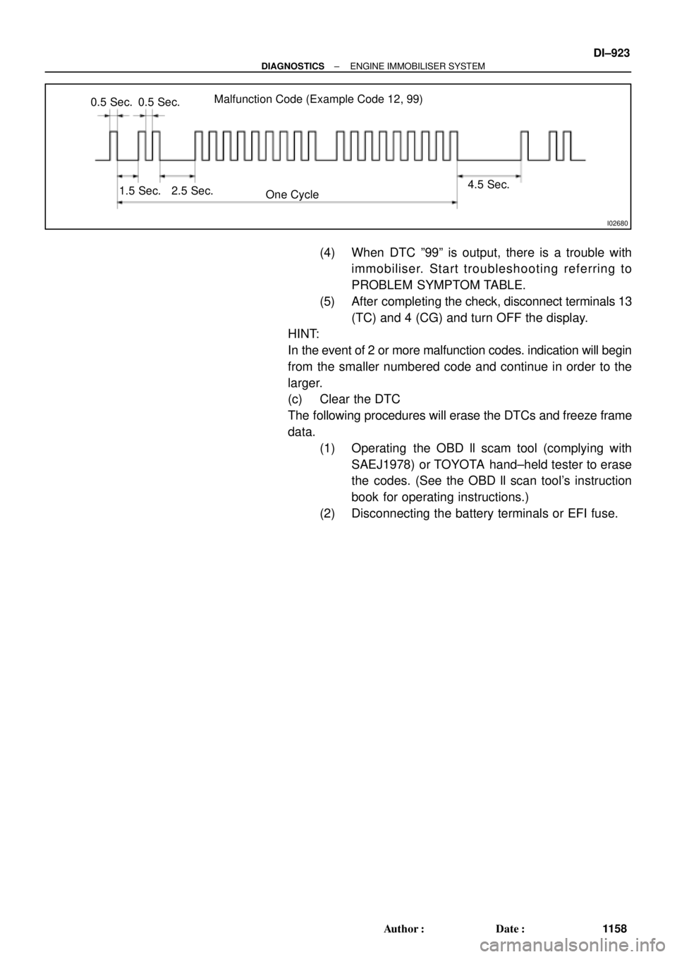
I02680
Malfunction Code (Example Code 12, 99)
0.5 Sec. 0.5 Sec.
1.5 Sec. 2.5 Sec.
One Cycle4.5 Sec.
± DIAGNOSTICSENGINE IMMOBILISER SYSTEM
DI±923
1158 Author�: Date�:
(4) When DTC º99º is output, there is a trouble with
immobiliser. Start troubleshooting referring to
PROBLEM SYMPTOM TABLE.
(5) After completing the check, disconnect terminals 13
(TC) and 4 (CG) and turn OFF the display.
HINT:
In the event of 2 or more malfunction codes. indication will begin
from the smaller numbered code and continue in order to the
larger.
(c) Clear the DTC
The following procedures will erase the DTCs and freeze frame
data.
(1) Operating the OBD ll scam tool (complying with
SAEJ1978) or TOYOTA hand±held tester to erase
the codes. (See the OBD ll scan tool's instruction
book for operating instructions.)
(2) Disconnecting the battery terminals or EFI fuse.