Page 3751 of 4770

MA001±10
± MAINTENANCEOUTSIDE VEHICLE
MA±1
44 Author�: Date�:
OUTSIDE VEHICLE
GENERAL MAINTENANCE
These are maintenance and inspection items which are considered to be the owner's responsibility.
They can be done by the owner or they can have them done at a service shop.
These items include those which should be checked on a daily basis, those which, in most cases, do not
require (special) tools and those which are considered to be reasonable for the owner to do.
Items and procedures for general maintenance are as follows.
1. GENERAL NOTES
�Maintenance items may vary from country to country. Check the owner's manual supplement in which
the maintenance schedule is shown.
�Every service item in the periodic maintenance schedule must be performed.
�Periodic maintenance service must be performed according to whichever interval in the periodic main-
tenance schedule occurs first, the odometer reading (miles) or the time interval (months).
�Maintenance service after the last period should be performed at the same interval as before unless
otherwise noted.
�Failure to do even one item an cause the engine to run poorly and increase exhaust emissions.
2. TIRES
(a) Check the pressure with a gauge. If necessary, adjust.
(b) Check for cuts, damage or excessive wear.
3. WHEEL NUTS
When checking the tires, check the nuts for looseness or for missing nuts. If necessary, tighten them.
4. TIRE ROTATION
Check the owner's manual supplement in which the maintenance schedule is shown.
5. WINDSHIELD WIPER BLADES
Check for wear or cracks whenever they do not wipe clean. If necessary, replace.
6. FLUID LEAKS
(a) Check underneath for leaking fuel, oil, water or other fluid.
(b) If you smell gasoline fumes or notice any leak, have the cause found and corrected.
7. DOORS AND ENGINE HOOD
(a) Check that all doors and the tailgate operate smoothly, and that all latches lock securely.
(b) Check that the engine hood secondary latch secures the hood from opening when the primary latch
is released.
Page 3758 of 4770
MA0676B00995
MA00O±01
N21126
N21125
MA±8
± MAINTENANCEBODY
51 Author�: Date�:
BODY
INSPECTION
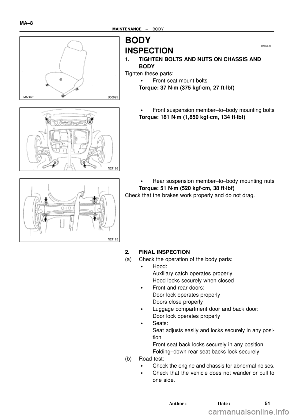
1. TIGHTEN BOLTS AND NUTS ON CHASSIS AND
BODY
Tighten these parts:
�Front seat mount bolts
Torque: 37 N´m (375 kgf´cm, 27 ft´lbf)
�Front suspension member±to±body mounting bolts
Torque: 181 N´m (1,850 kgf´cm, 134 ft´lbf)
�Rear suspension member±to±body mounting nuts
Torque: 51 N´m (520 kgf´cm, 38 ft´lbf)
Check that the brakes work properly and do not drag.
2. FINAL INSPECTION
(a) Check the operation of the body parts:
�Hood:
Auxiliary catch operates properly
Hood locks securely when closed
�Front and rear doors:
Door lock operates properly
Doors close properly
�Luggage compartment door and back door:
Door lock operates properly
�Seats:
Seat adjusts easily and locks securely in any posi-
tion
Front seat back locks securely in any position
Folding±down rear seat backs lock securely
(b) Road test:
�Check the engine and chassis for abnormal noises.
�Check that the vehicle does not wander or pull to
one side.
Page 4031 of 4770

SS0BY±01
± SERVICE SPECIFICATIONSBODY
SS±69
232 Author�: Date�:
BODY
TORQUE SPECIFICATION
Part tightenedN´mkgf´cmft´lbf
FRONT BUMPER±±±
Front bumper cover x Body5.55549 in.´lbf
Front bumper reinforcement x Body3435025
REAR BUMPER±±±
Rear bumper cover x Body5.05043 in.´lbf
Rear bumper reinforcement x Body3435025
HOOD±±±
Hood hinge x Hood2626019
Hood lock x Body8.08071 in.´lbf
FRONT AND REAR DOOR±±±
Front door hinge x Body3131022
Rear door hinge x Body2626019
Door hinge x Door panel2626019
Door lock striker x Body2626019
Outside rear view mirror x Front door panel5.55549
Door inside handle x Door panel3.53531 in.´lbf
Door glass x Window regulator8.08071 in.´lbf
Window regulator x Door panel5.55549 in.´lbf
Door lock x Door panel5.05043 in.´lbf
Door outside handle x Door panel7.07061 in.´lbf
Door check x Body3030022
Door check x Door panel8.08071 in.´lbf
LUGGAGE COMPARTMENT DOOR AND HINGE±±±
Luggage door hinge x Luggage door8.08071 in.´lbf
Luggage door lock striker x Body5.55549 in.´lbf
Luggage door lock x Luggage door5.55549 in.´lbf
FRONT WIPER AND WASHER±±±
Wiper motor assembly x Body2424518
Wiper arm x Wiper pivot5.55549 in.´lbf
SLIDING ROOF±±±
Sliding roof assembly x Body5.55549 in.´lbf
INSTRUMENT PANEL±±±
Front passenger airbag assembly x Reinforcement2020014
Steering wheel lock nut3536026
SEAT±±±
Front Seat (Power Seat for TMC Made)±±±
Hinge cover x Seatback frame1818513
Seatback frame x Power seat adjuster1515011
Seatback frame x Side airbag assembly6.06153 in.´lbf
Front Seat (Manual Seat for TMC Made)±±±
Front seat adjuster x Body3737527
Page 4183 of 4770
AB0089
Secondary Lock
Primary LockLockLock
Primary Lock Incomplete
(Secondary Lock Prevented)Primary Lock Complete
(Secondary Lock Permitted)Twin±Lock Completed
Z14034
Fig.1
Fig.2Power Source
Safing
Sensor
Squibs
Deceleration
Sensor RS±8
± SUPPLEMENTAL RESTRAINT SYSTEMSRS AIRBAG
2153 Author�: Date�:
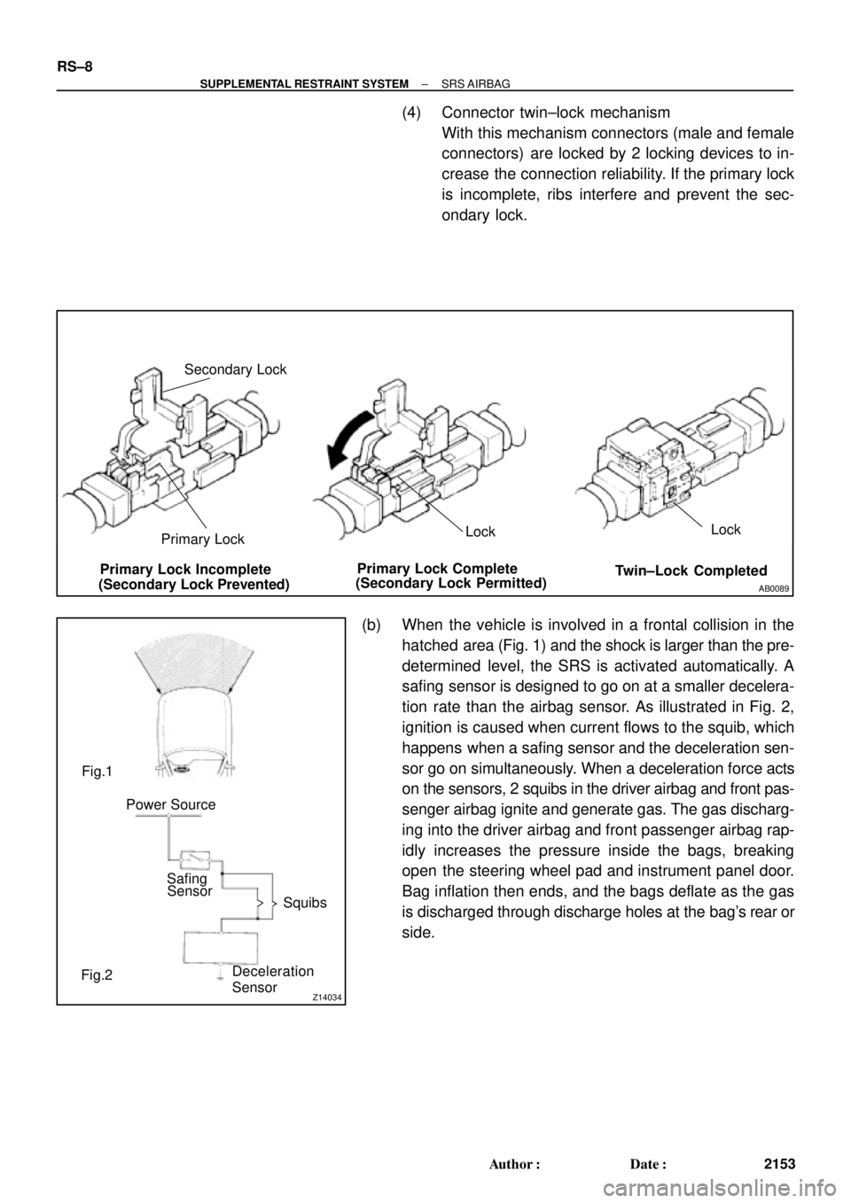
(4) Connector twin±lock mechanism
With this mechanism connectors (male and female
connectors) are locked by 2 locking devices to in-
crease the connection reliability. If the primary lock
is incomplete, ribs interfere and prevent the sec-
ondary lock.
(b) When the vehicle is involved in a frontal collision in the
hatched area (Fig. 1) and the shock is larger than the pre-
determined level, the SRS is activated automatically. A
safing sensor is designed to go on at a smaller decelera-
tion rate than the airbag sensor. As illustrated in Fig. 2,
ignition is caused when current flows to the squib, which
happens when a safing sensor and the deceleration sen-
sor go on simultaneously. When a deceleration force acts
on the sensors, 2 squibs in the driver airbag and front pas-
senger airbag ignite and generate gas. The gas discharg-
ing into the driver airbag and front passenger airbag rap-
idly increases the pressure inside the bags, breaking
open the steering wheel pad and instrument panel door.
Bag inflation then ends, and the bags deflate as the gas
is discharged through discharge holes at the bag's rear or
side.
Page 4207 of 4770
AB0158
SSTBattery
H03287
H08317SST
R13455
10 m (33 ft) or more
H03286
RS±32
± SUPPLEMENTAL RESTRAINT SYSTEMFRONT PASSENGER AIRBAG ASSEMBLY
2177 Author�: Date�:
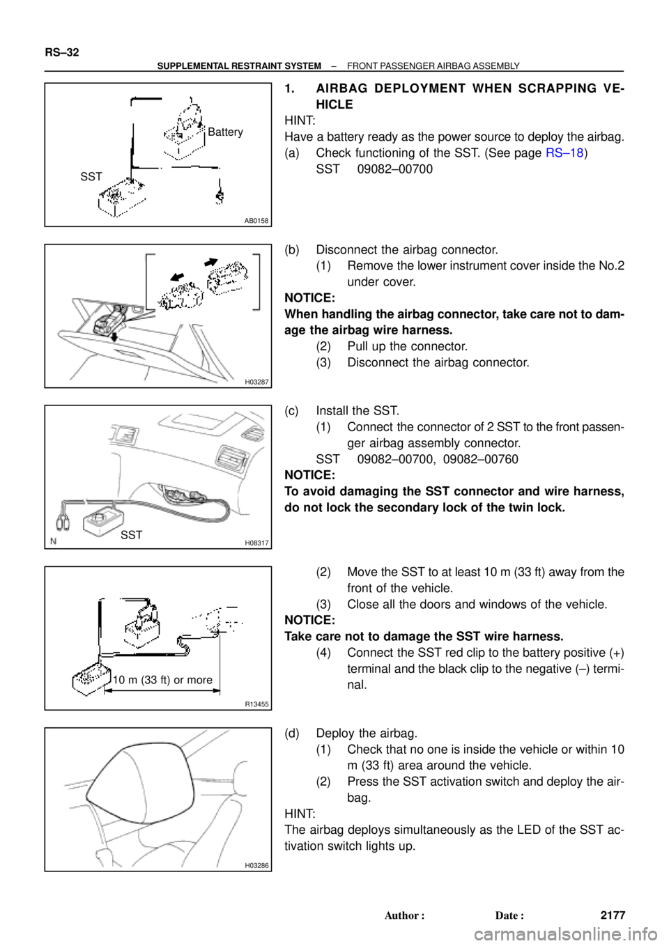
1. AIRBAG DEPLOYMENT WHEN SCRAPPING VE-
HICLE
HINT:
Have a battery ready as the power source to deploy the airbag.
(a) Check functioning of the SST. (See page RS±18)
SST 09082±00700
(b) Disconnect the airbag connector.
(1) Remove the lower instrument cover inside the No.2
under cover.
NOTICE:
When handling the airbag connector, take care not to dam-
age the airbag wire harness.
(2) Pull up the connector.
(3) Disconnect the airbag connector.
(c) Install the SST.
(1) Connect the connector of 2 SST to the front passen-
ger airbag assembly connector.
SST 09082±00700, 09082±00760
NOTICE:
To avoid damaging the SST connector and wire harness,
do not lock the secondary lock of the twin lock.
(2) Move the SST to at least 10 m (33 ft) away from the
front of the vehicle.
(3) Close all the doors and windows of the vehicle.
NOTICE:
Take care not to damage the SST wire harness.
(4) Connect the SST red clip to the battery positive (+)
terminal and the black clip to the negative (±) termi-
nal.
(d) Deploy the airbag.
(1) Check that no one is inside the vehicle or within 10
m (33 ft) area around the vehicle.
(2) Press the SST activation switch and deploy the air-
bag.
HINT:
The airbag deploys simultaneously as the LED of the SST ac-
tivation switch lights up.
Page 4218 of 4770
AB0158
Battery
SST
H01353
H01354
Battery
SST
R13455
10 m (33 ft) or more
H01326
± SUPPLEMENTAL RESTRAINT SYSTEMSIDE AIRBAG ASSEMBLY (TMC Made)
RS±43
2188 Author�: Date�:
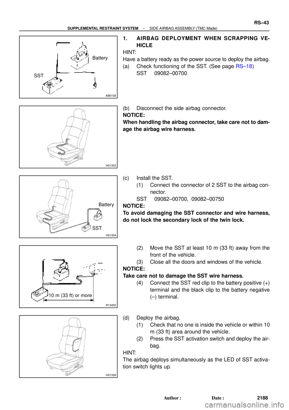
1. AIRBAG DEPLOYMENT WHEN SCRAPPING VE-
HICLE
HINT:
Have a battery ready as the power source to deploy the airbag.
(a) Check functioning of the SST. (See page RS±18)
SST 09082±00700
(b) Disconnect the side airbag connector.
NOTICE:
When handling the airbag connector, take care not to dam-
age the airbag wire harness.
(c) Install the SST.
(1) Connect the connector of 2 SST to the airbag con-
nector.
SST 09082±00700, 09082±00750
NOTICE:
To avoid damaging the SST connector and wire harness,
do not lock the secondary lock of the twin lock.
(2) Move the SST at least 10 m (33 ft) away from the
front of the vehicle.
(3) Close all the doors and windows of the vehicle.
NOTICE:
Take care not to damage the SST wire harness.
(4) Connect the SST red clip to the battery positive (+)
terminal and the black clip to the battery negative
(±) terminal.
(d) Deploy the airbag.
(1) Check that no one is inside the vehicle or within 10
m (33 ft) area around the vehicle.
(2) Press the SST activation switch and deploy the air-
bag.
HINT:
The airbag deploys simultaneously as the LED of SST activa-
tion switch lights up.
Page 4299 of 4770
SR06H±03
W03348
Torx ScrewSteering Wheel Pad
Steering Wheel
Torx Screw
Steering Wheel Lower
No.2 Cover
Steering Column Assembly
Intermediate Shaft Assembly
No.1 Lower Instrument Panel Combination Switch
(w/ Spiral Cable)Steering Wheel Lower
No.2 Cover
Column
Upper Cover
Lower No.2
Cover
Column Lower Cover
Lower Instrument
Finish Panel
Hood Lock Control Cable
Clip
Front Door Inside Scuff Plate
Cowl Side Trim LH Lower
Instrument Panel
35 (360, 26)
25 (260, 19)
7.1 (72, 63 in.´lbf)
35 (360, 26)
35 (360, 26)
7.1 (72, 63 in.´lbf)
N´m (kgf´cm, ft´lbf) : Specified torque
± STEERINGTILT STEERING COLUMN
SR±9
2104 Author�: Date�:
TILT STEERING COLUMN
COMPONENTS
Page 4302 of 4770
W03303
Matchmarks SR±12
± STEERINGTILT STEERING COLUMN
2107 Author�: Date�:
3. REMOVE UPPER AND LOWER COLUMN COVERS
(a) Remove the lower No.2 cover from the lower cover.
(b) Remove the 3 screws.
4. REMOVE FRONT DOOR INSIDE SCUFF PLATE
5. REMOVE COWL SIDE TRIM
Remove the clip.
6. REMOVE No.1 LOWER INSTRUMENT PANEL
(a) Remove the 2 screws.
(b) Disconnect the hood lock control cable.
7. REMOVE LH LOWER INSTRUMENT PANEL
Remove the 4 bolts.
8. REMOVE LOWER INSTRUMENT FINISH PANEL
9. REMOVE COMBINATION SWITCH WITH SPIRAL
CABLE
(a) Disconnect the 3 connectors.
(b) Disconnect the airbag connector.
(c) Remove the 3 screws.
10. REMOVE SPIRAL CABLE
(See page BE±23)
NOTICE:
Do not disassemble the cable or apply oil to it.
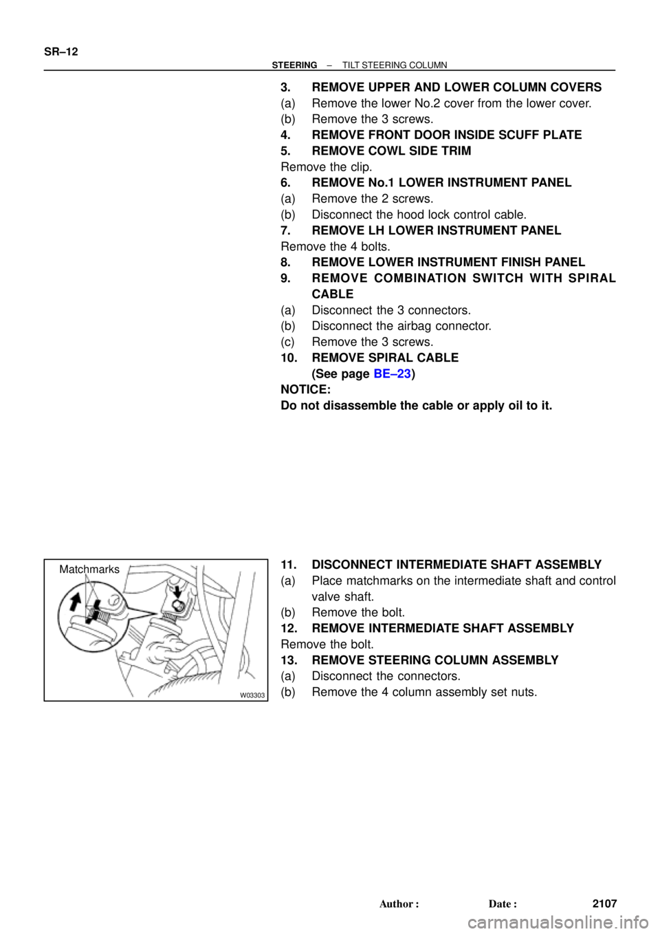
11. DISCONNECT INTERMEDIATE SHAFT ASSEMBLY
(a) Place matchmarks on the intermediate shaft and control
valve shaft.
(b) Remove the bolt.
12. REMOVE INTERMEDIATE SHAFT ASSEMBLY
Remove the bolt.
13. REMOVE STEERING COLUMN ASSEMBLY
(a) Disconnect the connectors.
(b) Remove the 4 column assembly set nuts.