Page 4306 of 4770

SR06M±01
W03303
Matchmarks
W02655
Mark SR±16
± STEERINGTILT STEERING COLUMN
2111 Author�: Date�:
INSTALLATION
1. INSTALL STEERING COLUMN ASSEMBLY
(a) Torque the 4 column assembly set nuts.
Torque: 25 N´m (260 kgf´cm, 19 ft´lbf)
(b) Connect the connectors.
2. INSTALL INTERMEDIATE SHAFT ASSEMBLY
Torque the bolt.
Torque: 35 N´m (360 kgf´cm, 26 ft´lbf)
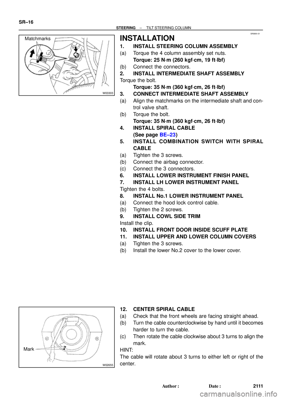
3. CONNECT INTERMEDIATE SHAFT ASSEMBLY
(a) Align the matchmarks on the intermediate shaft and con-
trol valve shaft.
(b) Torque the bolt.
Torque: 35 N´m (360 kgf´cm, 26 ft´lbf)
4. INSTALL SPIRAL CABLE
(See page BE±23)
5. INSTALL COMBINATION SWITCH WITH SPIRAL
CABLE
(a) Tighten the 3 screws.
(b) Connect the airbag connector.
(c) Connect the 3 connectors.
6. INSTALL LOWER INSTRUMENT FINISH PANEL
7. INSTALL LH LOWER INSTRUMENT PANEL
Tighten the 4 bolts.
8. INSTALL No.1 LOWER INSTRUMENT PANEL
(a) Connect the hood lock control cable.
(b) Tighten the 2 screws.
9. INSTALL COWL SIDE TRIM
Install the clip.
10. INSTALL FRONT DOOR INSIDE SCUFF PLATE
11. INSTALL UPPER AND LOWER COLUMN COVERS
(a) Tighten the 3 screws.
(b) Install the lower No.2 cover to the lower cover.
12. CENTER SPIRAL CABLE
(a) Check that the front wheels are facing straight ahead.
(b) Turn the cable counterclockwise by hand until it becomes
harder to turn the cable.
(c) Then rotate the cable clockwise about 3 turns to align the
mark.
HINT:
The cable will rotate about 3 turns to either left or right of the
center.
Page 4414 of 4770

W03303
Matchmarks SR±12
± STEERINGTILT STEERING COLUMN
2097 Author�: Date�:
2001 CAMRY (RM819U)
3. REMOVE UPPER AND LOWER COLUMN COVERS
(a) Remove the lower No.2 cover from the lower cover.
(b) Remove the 3 screws, upper and lower column covers.
4. REMOVE FRONT DOOR INSIDE SCUFF PLATE
5. REMOVE COWL SIDE TRIM
Remove the clip and cowl side trim.
6. REMOVE No.1 LOWER INSTRUMENT PANEL
(a) Remove the 2 screws.
(b) Disconnect the hood lock control cable.
(c) Remove the No.1 lower instrument panel.
7. REMOVE LH LOWER INSTRUMENT PANEL
Remove the 4 bolts and LH lower instrument panel.
8. REMOVE LOWER INSTRUMENT FINISH PANEL
9. REMOVE COMBINATION SWITCH WITH SPIRAL
CABLE
(a) Disconnect the 3 connectors.
(b) Disconnect the airbag connector.
(c) Remove the 3 screws and combination switch with spiral
cable.
10. REMOVE SPIRAL CABLE (See page BE±23)
NOTICE:
Do not disassemble the cable or apply oil to it.
11. DISCONNECT INTERMEDIATE SHAFT ASSEMBLY
(a) Place matchmarks on the intermediate shaft and control
valve shaft.
(b) Remove the bolt and disconnect the intermediate shaft
assembly.
12. REMOVE INTERMEDIATE SHAFT ASSEMBLY
Remove the bolt and intermediate shaft assembly.
13. REMOVE STEERING COLUMN ASSEMBLY
(a) Disconnect the connectors.
(b) Remove the 4 column assembly set nuts and steering col-
umn assembly.
Page 4431 of 4770

Toyota Supports ASE CertificationPage 1 of 2
AX005±00Title:
RS3000 TVIP AUTOMATIC DOOR LOCK
FEATURE PROGRAMMING
Models:
All Models
Technical Service
BULLETIN
April 14, 2000
As a convenience feature, the RS3000 TVIP system is programmed to automatically lock
all of the vehicle's doors (for vehicles equipped with power door locks) when the ignition
key is turned to ªONº or ªSTARTº, and unlock them when the key is turned back to ªACCº
or ªLOCKº. The initial factory setting of this programmable feature is ªONº. For some
customers however, this feature is not desirable due to instances of passenger lockout
when the driver enters the vehicle first and starts the ignition.
For vehicles equipped with RS3000 TVIP, this bulletin advises the dealers to
communicate the following information to the customers at vehicle delivery:
1. Inform the customers of the RS3000 system's automatic (ignition controlled) door
lock/unlock feature.
2. Inquire about the customers' preference for it to be set ªONº or ªOFFº.
3. Reprogram the feature's setting according to the customer's preference.
To change the feature's operation mode, follow the programming procedures on page 2.
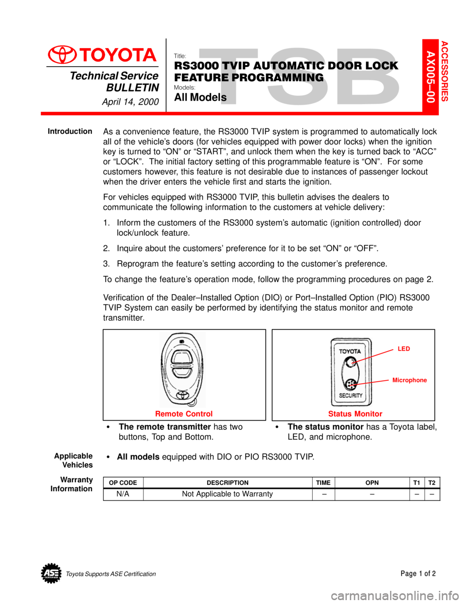
Verification of the Dealer±Installed Option (DIO) or Port±Installed Option (PIO) RS3000
TVIP System can easily be performed by identifying the status monitor and remote
transmitter.
�The remote transmitter has two
buttons, Top and Bottom.�The status monitor has a Toyota label,
LED, and microphone.
Remote Control
LED
Status Monitor
Microphone
�All models equipped with DIO or PIO RS3000 TVIP.
OP CODEDESCRIPTIONTIMEOPNT1T2
N/ANot Applicable to Warranty ±±±±
ACCESSORIES
Introduction
Applicable
Vehicles
Warranty
Information
Page 4432 of 4770

RS30000 TVIP AUTOMATIC DOOR LOCK FEATURE PROGRAMMING ± AX005±00 April 14, 2000
Page 2 of 2
AUTOMATIC (IGNITION±CONTROLLED) DOOR LOCKING/UNLOCKING FUNCTION
The factory setting for the Automatic Door Locking/Unlocking Function is ªONº.
To change this feature's operation, follow the steps below:
1. Sit in the driver's seat with driver's door open.
2. Insert the key into the ignition switch, and turn it to ªONº position (not ªACCº)
5 times (ON > LOCK > ON > LOCK > ON > LOCK > ON > LOCK > ON) within a
10 second period.
System Response: The STATUS MONITOR's LED turns on, and the PIEZO
BUZZER sounds once.
NOTE:
You must perform the next steps within 30 seconds.
3. Select the customer's preferred operating mode.
ModeProgramming StepProgramming Completion
AUTOMATIC DOOR
LOCKING/UNLOCKING ªONºClose the driver's door.
Turn the ignition switch to the
ªLOCKº position.
System Response:
The PIEZO BUZZER sounds
once, and the exterior lights
flash once.
AUTOMATIC DOOR
LOCKING/UNLOCKING ªOFFºClose the driver's door,
then open and close it
one more time.
Turn the ignition switch to the
ªLOCKº position.
System Response:
The PIEZO BUZZER sounds
twice, and the exterior lights
flash twice.
Programming
Procedure
Page 4434 of 4770

RS3000 TVIP PROGRAMMING CHANGES FOR GBS ± AX006±99 April 23, 1999
Page 2 of 2
When performing the RS3000 System Test, check the Glass Breakage Sensor sensitivity
as follows:
1. Press and release the Remote Control's top button to arm the system.
2. Wait two seconds.
3. With the tip of the ignition key (or striker tool), softly tap the center of the driver's door
window glass.
�If the system is triggered (horn sounds for 20 seconds), the sensitivity must be
adjusted. Turn the Glass Breakage Sensor ECU's adjustment screw clockwise
one notch, and repeat this step again.
4. If the system is not triggered, repeat the glass tapping with moderate force.
�The system should trigger when the glass is tapped with moderate force. If it is
not triggered, turn the Glass Breakage Sensor ECU's adjustment screw clockwise
one notch, and repeat this step again.
CAUTION:
Use caution when performing the step above. Do not tap the window glass with too
much force, or the glass may crack or break. Use extra caution when the temperature
is extremely cold.
NOTE:
The Owner's Guide included in the RS3000 Base Kit is changed to reflect the
(GBS logic) improvement. There is no change to the GBS ECU itself. Repair
Procedure
Page 4477 of 4770

DOOR GLASS DISPLACEMENT ± BO017±99 November 26, 1999
Page 2 of 2
1. Lower the door glass, disconnect the power window switch, remove the front door
trim panel, speaker, and loosen the door mirror mounts to gain access to the door
glass and lower frames. Remove the front lower frame (2 screws).
2. Locate the lower window frame mounting hole on the door (see illlustration). Place a
towel or shop rag in the speaker hole to catch metal chips. Using a round file or die
grinder, enlarge the hole 2 mm toward the speaker (rear of the vehicle). Remove the
towel or shop rag and any metal chips in the door. Apply touch±up paint or rust
preventative to the hole.
2 mm"u
3. Install a rubber stopper to the lower window frame according to directions in TSB
BO012±99.
4. Install the lower window frame. Assure the frame is tight against the glass and the
run is fully inserted in the lower window frame channel.
5. Temporarily connect the power window switch and operate the window. Check to
assure the door glass fully opens and closes easily.
6. Reinstall the door panel and components, check lock/unlock function and door
opening handle function.
Repair
Procedure
Page 4592 of 4770

Toyota Supports ASE CertificationPage 1 of 2
EL008±98Title:
PROGRAMMING OEM WIRELESS
DOOR LOCK REMOTE TRANSMITTERS
Models:
'97 ± '99 Camry
Technical Service
BULLETIN
December 4, 1998
This bulletin describes procedures used to program the three button remote transmitter to
vehicles that are equipped with Wireless Door Lock Control. The following information
applies
only to the Factory Wireless Door Lock Control, not dealer or port installed
options that also utilize remotes, such as VIP Keyless Entry/RS3000 or any aftermarket
system.
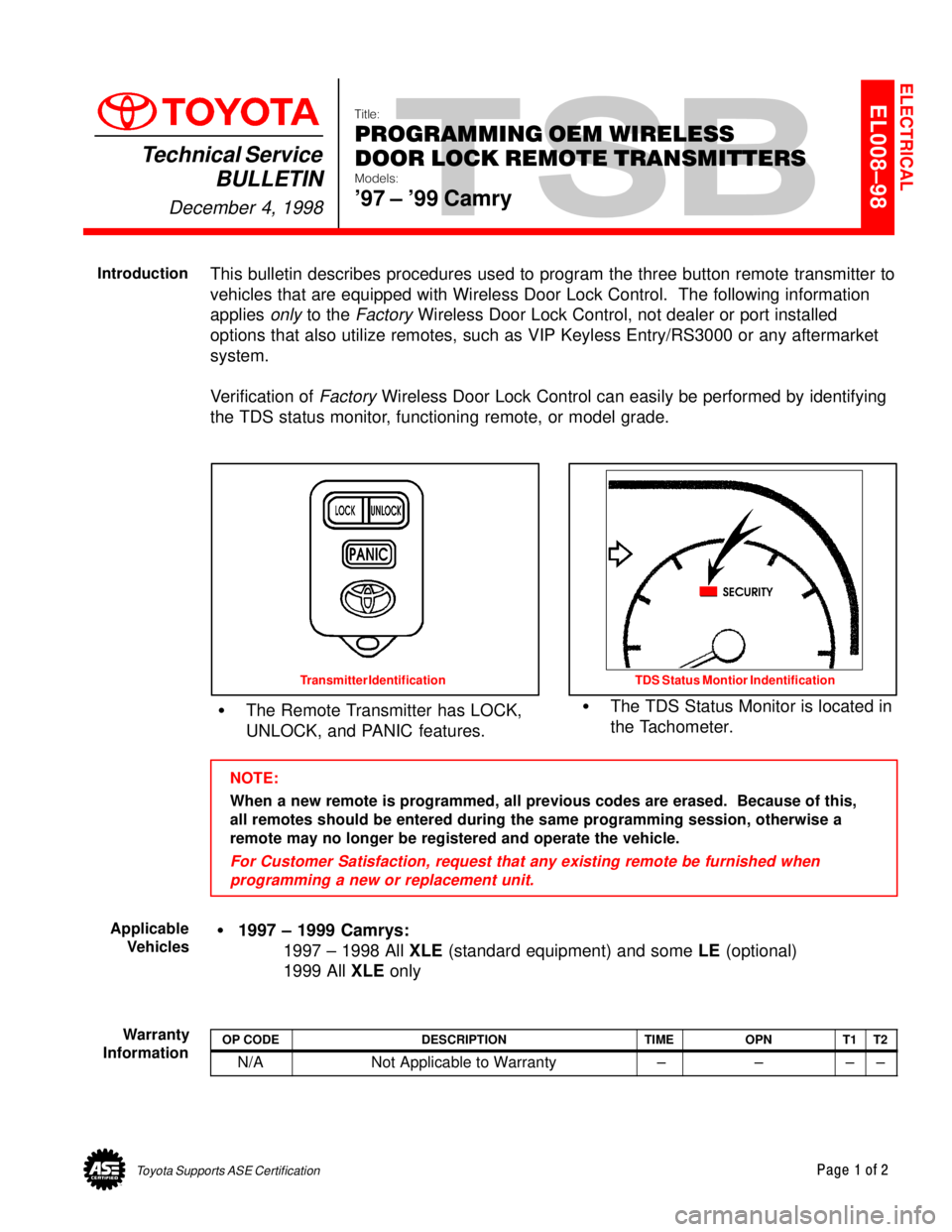
Verification of
Factory Wireless Door Lock Control can easily be performed by identifying
the TDS status monitor, functioning remote, or model grade.
�The Remote Transmitter has LOCK,
UNLOCK, and PANIC features.�The TDS Status Monitor is located in
the Tachometer.
Transmitter Identification TDS Status Montior Indentification
NOTE:
When a new remote is programmed, all previous codes are erased. Because of this,
all remotes should be entered during the same programming session, otherwise a
remote may no longer be registered and operate the vehicle.
For Customer Satisfaction, request that any existing remote be furnished when
programming a new or replacement unit.
�1997 ± 1999 Camrys:
1997 ± 1998 All XLE (standard equipment) and some LE (optional)
1999 All XLE only
OP CODEDESCRIPTIONTIMEOPNT1T2
N/ANot Applicable to Warranty ±±±±
ELECTRICAL
Introduction
Applicable
Vehicles
Warranty
Information
Page 4593 of 4770

PROGRAMMING OEM WIRELESS DOOR LOCK REMOTE TRANSMITTERS ± EL008±98 December 4, 1998
Page 2 of 2
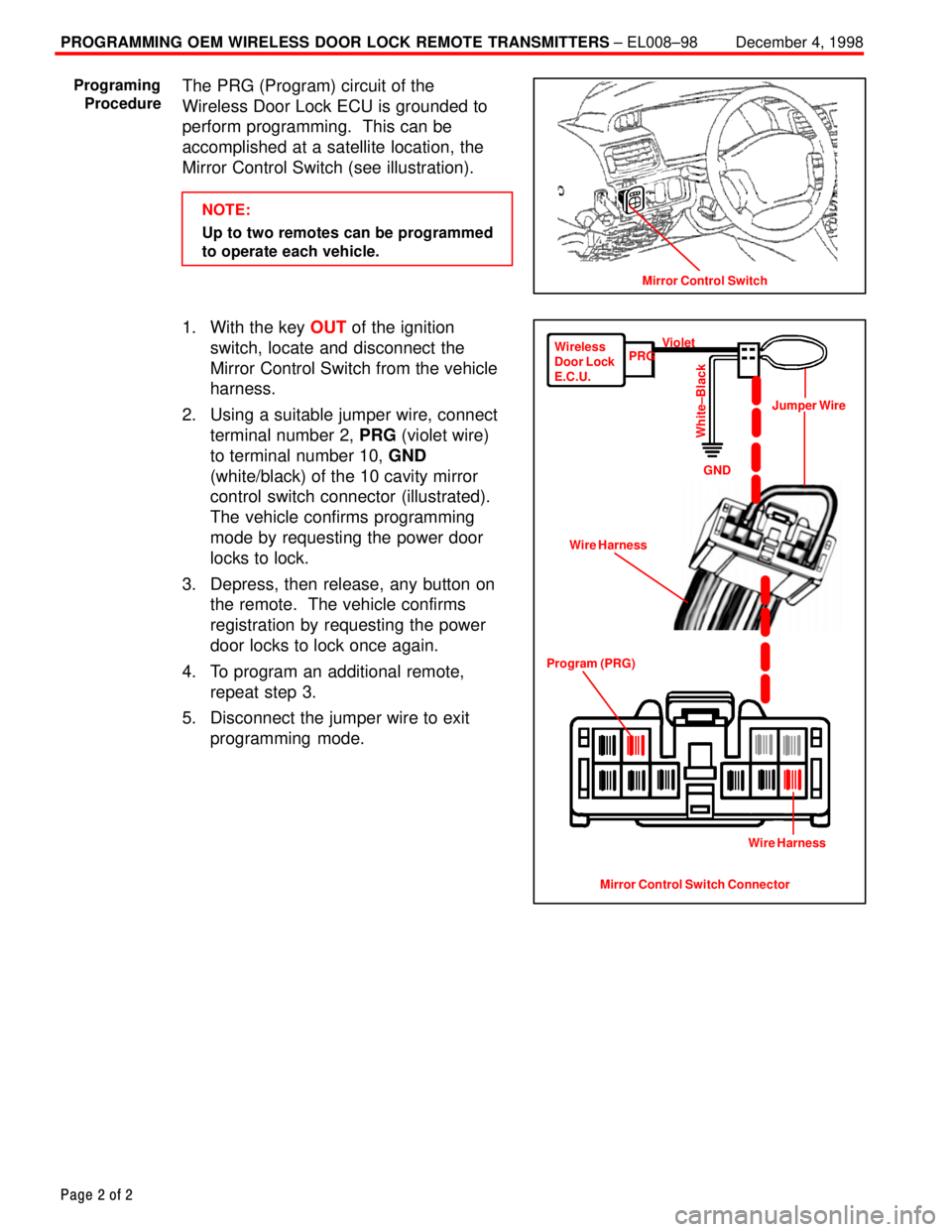
The PRG (Program) circuit of the
Wireless Door Lock ECU is grounded to
perform programming. This can be
accomplished at a satellite location, the
Mirror Control Switch (see illustration).
NOTE:
Up to two remotes can be programmed
to operate each vehicle.
1. With the key OUT of the ignition
switch, locate and disconnect the
Mirror Control Switch from the vehicle
harness.
2. Using a suitable jumper wire, connect
terminal number 2, PRG (violet wire)
to terminal number 10, GND
(white/black) of the 10 cavity mirror
control switch connector (illustrated).
The vehicle confirms programming
mode by requesting the power door
locks to lock.
3. Depress, then release, any button on
the remote. The vehicle confirms
registration by requesting the power
door locks to lock once again.
4. To program an additional remote,
repeat step 3.
5. Disconnect the jumper wire to exit
programming mode.
Mirror Control Switch
Programing
Procedure
Mirror Control Switch Connector Program (PRG)Wire HarnessJumper Wire Wireless
Door Lock
E.C.U.PRGViolet
GND
White±Black
Wire Harness