Page 3271 of 4770
I01927
Theft Deterrent ECU
T4
13
IG B±R B
J17
C
J16B±R Instrument Panel J/B
8
1
ECU±IG
1
1B AM1
2
1K
4 B±Y AM1
2Ignition Switch
W
B±R
B±R 1
F9 ALT
FL BLOCK
F4
1
B±G
FL MAIN
Battery
1D
1K
IG1
± DIAGNOSTICSTHEFT DETERRENT SYSTEM
DI±851
1086 Author�: Date�:
Ignition Switch Circuit
CIRCUIT DESCRIPTION
When the ignition switch is turned to the ACC position, battery positive voltage is applied to the terminal ACC
of the ECU. Also, if the ignition switch is turned to the ON position, battery positive voltage is applied to the
terminals ACC and IG of the ECU. When the battery positive voltage is applied to the terminal ACC of the
ECU while the theft deterrent system is activated, the warning stops. Furthermore, power supplied from the
terminals ACC and IG of the ECU is used as power for the door courtesy switch, and position switch, etc.
WIRING DIAGRAM
DI06Z±06
Page 3275 of 4770
I00252
Theft Deterrent ECU
LUG 7
T4G±W C CJ33
J/C
G±W 2IF1G±W 2 1 Luggage Compartment
Door Key Lock and
Unlock Switch
BP
W±B
± DIAGNOSTICSTHEFT DETERRENT SYSTEM
DI±855
1090 Author�: Date�:
Luggage Compartment Door Key Lock and Unlock Switch Circuit
CIRCUIT DESCRIPTION
The luggage compartment door key lock and unlock switch goes ON when the luggage compartment door
key cylinder is turned to the unlock side with the key.
WIRING DIAGRAM
DI071±04
Page 3276 of 4770

AB0119
I00271I00277
ON
1
(+) (±)
I00270
21
DI±856
± DIAGNOSTICSTHEFT DETERRENT SYSTEM
1091 Author�: Date�:
INSPECTION PROCEDURE
1 Check voltage between terminal 1 of luggage compartment door key lock and
unlock switch connector and body ground.
PREPARATION:
(a) Remove luggage compartment door trim.
(b) Turn ignition switch ON.
CHECK:
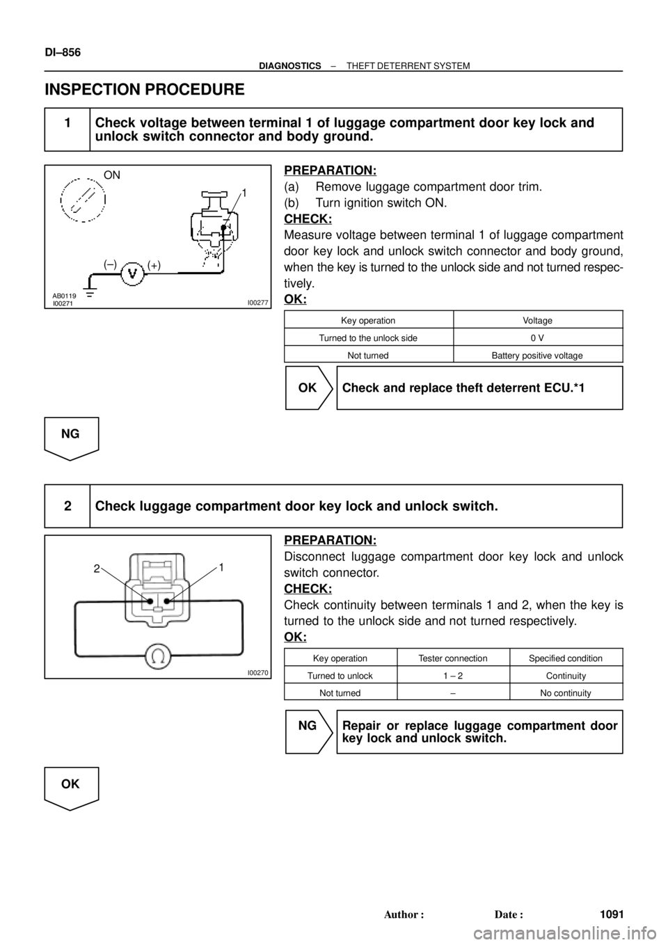
Measure voltage between terminal 1 of luggage compartment
door key lock and unlock switch connector and body ground,
when the key is turned to the unlock side and not turned respec-
tively.
OK:
Key operationVoltage
Turned to the unlock side0 V
Not turnedBattery positive voltage
OK Check and replace theft deterrent ECU.*1
NG
2 Check luggage compartment door key lock and unlock switch.
PREPARATION:
Disconnect luggage compartment door key lock and unlock
switch connector.
CHECK:
Check continuity between terminals 1 and 2, when the key is
turned to the unlock side and not turned respectively.
OK:
Key operationTester connectionSpecified condition
Turned to unlock1 ± 2Continuity
Not turned±No continuity
NG Repair or replace luggage compartment door
key lock and unlock switch.
OK
Page 3280 of 4770
I08430
Door Key Lock and
Unlock Switch RH Instrument Panel J/BTheft Deterrent ECU
B9
UL3 J6
J/C Door Key Lock and
Unlock Switch LH
L2 T4
8
T4
UL2 10
T4 B 3
IE1
L±W UNLOCK
R±G R±G R±G
4
IE1
L±WL±W BB 3
2
LOCK J38
J/C
AA1
W±B
*1
IE W±BW±B
*1
20
IE1
7
1G3
1V
W±B
J37
J/C
L±W L±W4
IM1
3
IM1B 2
3AA
L L
L LOCK
UNLOCK
IJ20
IM1J39
J/C
AA1
W±B
*1W±B*1
W±B*2
W±B*2*1: TMC Made
*2: TMMK Made W±B DI±860
± DIAGNOSTICSTHEFT DETERRENT SYSTEM
1095 Author�: Date�:
Door Key Lock and Unlock Switch Circuit
CIRCUIT DESCRIPTION
The door key lock and unlock switch is built in the door key cylinder. When the key is turned to the lock side,
terminal 1 of the switch is grounded and when the key is turned to the unlock side, terminal 2 of the switch
is grounded.
WIRING DIAGRAM
DI073±06
Page 3281 of 4770

I00272
1
2
3
(±) (+)
± DIAGNOSTICSTHEFT DETERRENT SYSTEM
DI±861
1096 Author�: Date�:
INSPECTION PROCEDURE
1 Check door key lock and unlock switch.
PREPARATION:
(a) Remove the door trim and service hole cover.
(b) Disconnect the door key lock and unlock switch connec-
tor.
CHECK:
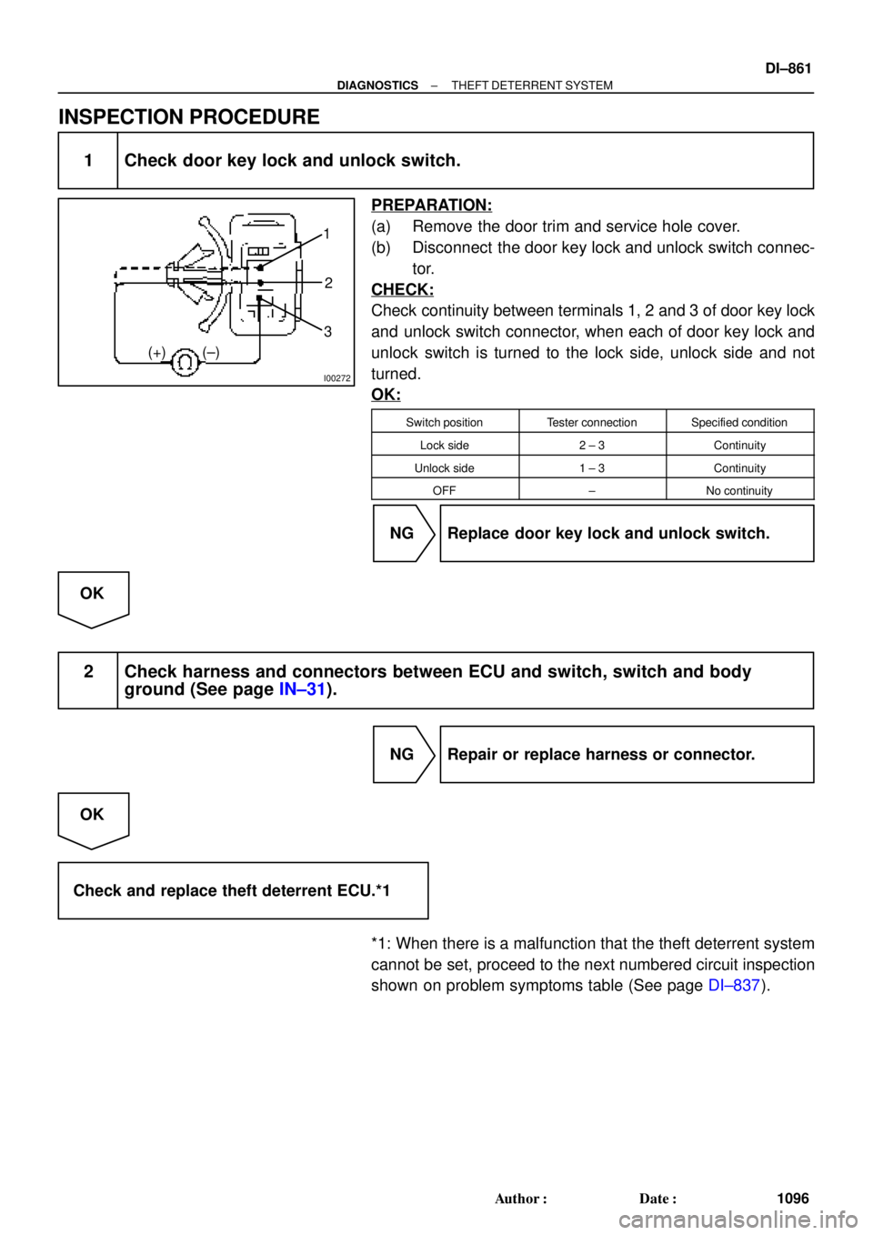
Check continuity between terminals 1, 2 and 3 of door key lock
and unlock switch connector, when each of door key lock and
unlock switch is turned to the lock side, unlock side and not
turned.
OK:
Switch positionTester connectionSpecified condition
Lock side2 ± 3Continuity
Unlock side1 ± 3Continuity
OFF±No continuity
NG Replace door key lock and unlock switch.
OK
2 Check harness and connectors between ECU and switch, switch and body
ground (See page IN±31).
NG Repair or replace harness or connector.
OK
Check and replace theft deterrent ECU.*1
*1: When there is a malfunction that the theft deterrent system
cannot be set, proceed to the next numbered circuit inspection
shown on problem symptoms table (See page DI±837).
Page 3282 of 4770

I08431
Theft Deterrent ECU
14
T4 Instrument Panel J/B
Door Unlock Detection
Switch Front LHJ6
J/C
L±RLSWD
LSWP
LSWR 15
T4
16
T4 L±R L±R11
IE1F F
W±B*1
IE
4
*1
1*21*1
4*2
J10E 4 1
W±B*1
J38
J/C
A A 20
IE1
W 7
1G 3
1V
W±B
W±B
*2
J37
J/C
C C
Y Y Y11
IM1 Door Unlock Detection
Switch Front RH
W±B
*1W±B*1
J39
J/C
A A
W±B
*2
20
IM1
W±B
IJ
L±Y J10EJ/C
L±Y
L±Y
L±Y
2
IF2 4
BO1 41 Door Unlock Detection
Switch Rear LH
Door Unlock Detection
Switch Rear RH W±B W±B6
BO1 A J40
J/C
BL
BN
IK
J9DL±Y L±Y
L±YW±B W±B
W±B W±B3
IN2 4
BP1 41 6
BP1
*1: TMC Made
*2: TMMK Made DI±862
± DIAGNOSTICSTHEFT DETERRENT SYSTEM
1097 Author�: Date�:
Door Unlock Detection Switch Circuit
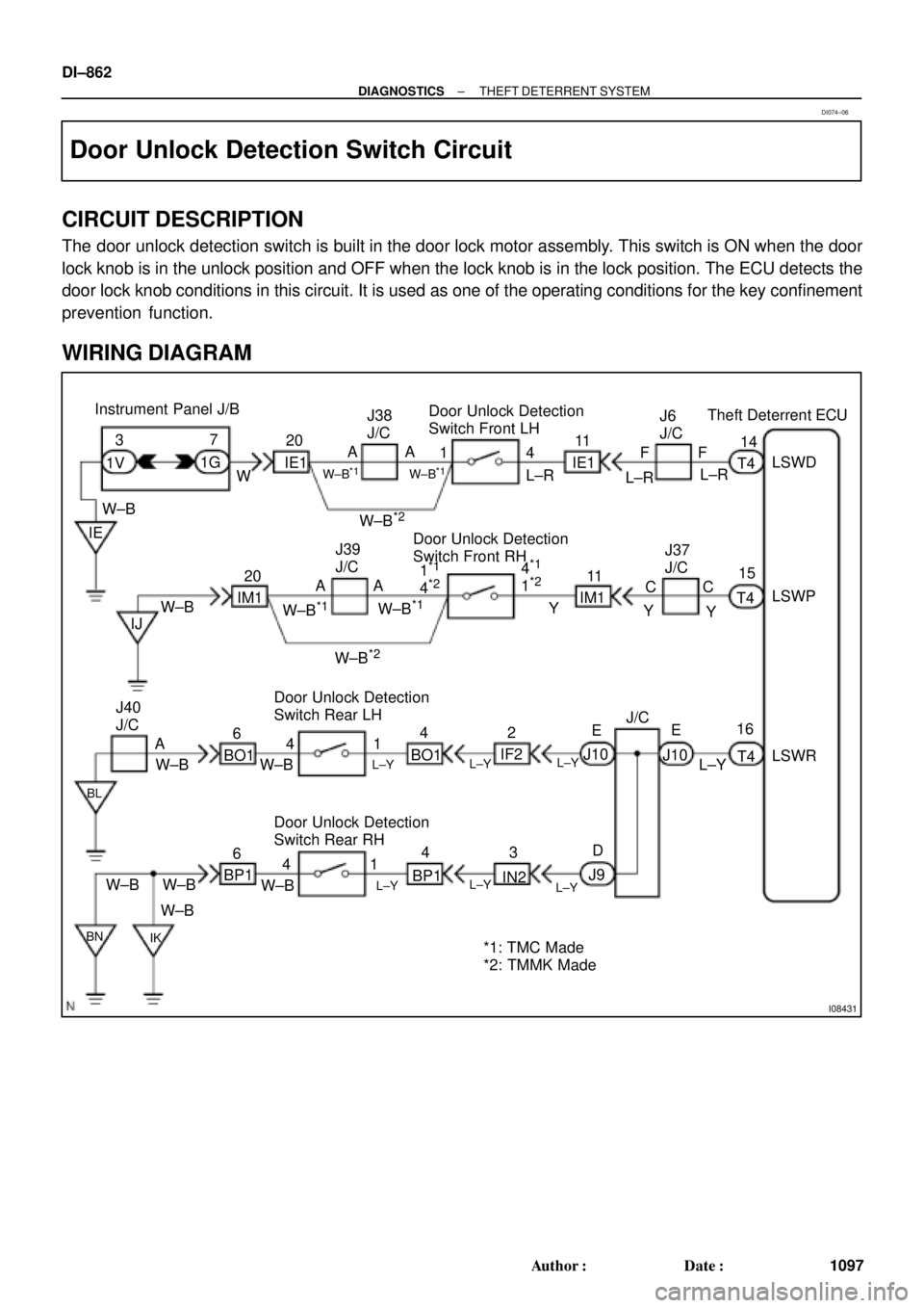
CIRCUIT DESCRIPTION
The door unlock detection switch is built in the door lock motor assembly. This switch is ON when the door
lock knob is in the unlock position and OFF when the lock knob is in the lock position. The ECU detects the
door lock knob conditions in this circuit. It is used as one of the operating conditions for the key confinement
prevention function.
WIRING DIAGRAM
DI074±06
Page 3283 of 4770

I00273
I00274I00278
LOCK
UNLOCK
41
(+)
(±)
± DIAGNOSTICSTHEFT DETERRENT SYSTEM
DI±863
1098 Author�: Date�:
INSPECTION PROCEDURE
1 Check Door Unlock Detection Switch.
PREPARATION:
(a) Remove the door trim and service hole cover.
(b) Disconnect door unlock detection switch connector.
CHECK:
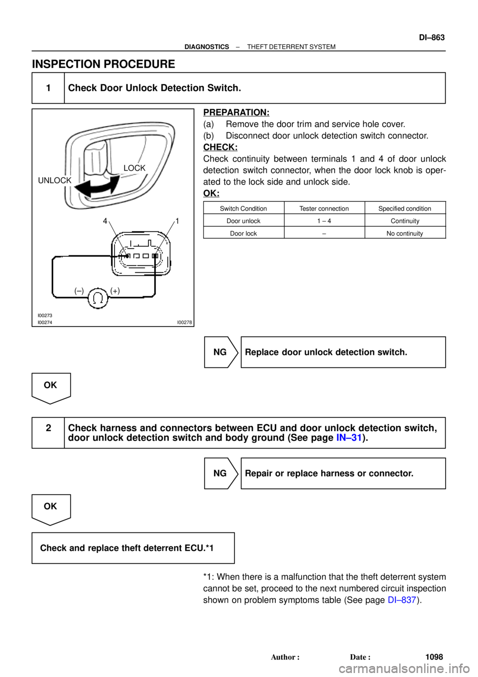
Check continuity between terminals 1 and 4 of door unlock
detection switch connector, when the door lock knob is oper-
ated to the lock side and unlock side.
OK:
Switch ConditionTester connectionSpecified condition
Door unlock1 ± 4Continuity
Door lock±No continuity
NG Replace door unlock detection switch.
OK
2 Check harness and connectors between ECU and door unlock detection switch,
door unlock detection switch and body ground (See page IN±31).
NG Repair or replace harness or connector.
OK
Check and replace theft deterrent ECU.*1
*1: When there is a malfunction that the theft deterrent system
cannot be set, proceed to the next numbered circuit inspection
shown on problem symptoms table (See page DI±837).
Page 3622 of 4770
BO0L2±01
H01975
Door Lock
Cylinder
Outside Handle Front Door Belt Moulding
Door Glass
Door FrameFront Door Upper Moulding
Outside
Rear View
Mirror
Door Glass
Run
5.5 (55, 49 in.´lbf)
5.5 (55, 49 in.´lbf)
5.0 (50, 43 in.´lbf)�
Door Lock
23 (230, 17)
Window Regulator
8.0 (80, 69 in.´lbf)
Door Hinge
X6
7.5 (75, 66 in.´lbf)
Regulator
Motor
X3
31 (310, 22)
26 (260, 19)
8.0 (80, 71 in.´lbf)
30 (300, 22)
31 (310, 22)
Door
Check
Door Hinge
26 (260, 19)
Speaker
Power Window Switch Rear Lower
FrameFront Lower
FrameFront Window Upper
Garnish
Inside Handle Bezel
3.5 (35, 31 in.´lbf)
Driver's Side:
Regulator
Motor
Ptdt
N´m (kgf´cm, ft´lbf) : Specified torqueInside Handle
Door Trim
� Precoated part Door Lock StrikerService Hole Cover BO±12
± BODYFRONT DOOR
2370 Author�: Date�:
2001 CAMRY (RM819U)
FRONT DOOR
COMPONENTS