Page 397 of 4770
Remove glove compartment.
(See page EG1±234) .
Measure voltage between terminal IGT of engine
control module connector and body ground
when engine is cranked.
Voltage: 0.5 ± 1.0 V
(Neither 0 V nor 5 V)
wDuring cranking or idling, check waveform between
terminal IGT and E1 of engine control module.
HINT: The correct waveform appears as shown in the
illustration on the left, with rectangle waves.
Check voltage between terminal IGT of engine control module
connector and body ground.
INSPECTION USING OSCILLOSCOPE Reference
Go to step
± 5S±FE ENGINECIRCUIT INSPECTIONEG1±347
Page 398 of 4770
Disconnect igniter connector.
Measure voltage between terminal 3 of igniter
connector and body ground, when ignition
switch is turned to ªONº and ªSTAº position.
Voltage: 9 ~ 14 V
Check for open and short in harness and connector between ignition
switch and ignition coil, ignition coil and igniter (See page IN±31). Check voltage between terminal 3 of igniter connector and body
ground.
Check and repair igniter power source
circuit.
Repair or replace harness or connector.
± 5S±FE ENGINECIRCUIT INSPECTIONEG1±348
Page 399 of 4770
For California spec.
(1) Disconnect ignition coil connector.
(2) Disconnect high±tension cord from ignition
coil.
Exc. California spec.
(1) Disconnect distributor connectors.
(2) Remove distributor cap and rotor.
(3) Remove ignition coil dust cover.
(1) Check primary coil.
Measure resistance between the positive
(+) and negative (±) terminals.
(2) Check secondary coil.
Measure resistance between the positive
(+) and high±tension terminals.
ªColdº is from ±10
�C (14�F) to 50�C (122�F) and
ªHotº is from 50
�C (122�F) to 100�C (212�F).
Check ignition coil.
Replace ignition coil.
Replace igniter.
Secondary
CoilPrimary
CoilResistanceCold
Cold
HotHot
± 5S±FE ENGINECIRCUIT INSPECTIONEG1±349
Page 400 of 4770
Disconnect igniter connector.
Measure voltage between terminal IGT of engine
control module connector and body ground
when engine is cranked.
Voltage: 0.5±1.0 V
(Neither 0 V nor 5 V)
Check for open and short in harness and connector in IGT signal
circuit between engine control module and igniter (See page IN±31). Disconnect igniter connector and check voltage between terminal
IGT of engine control module connector and body ground.
Check and replace engine control module.Repair or replace harness or connector.Replace igniter.
± 5S±FE ENGINECIRCUIT INSPECTIONEG1±350
Page 403 of 4770

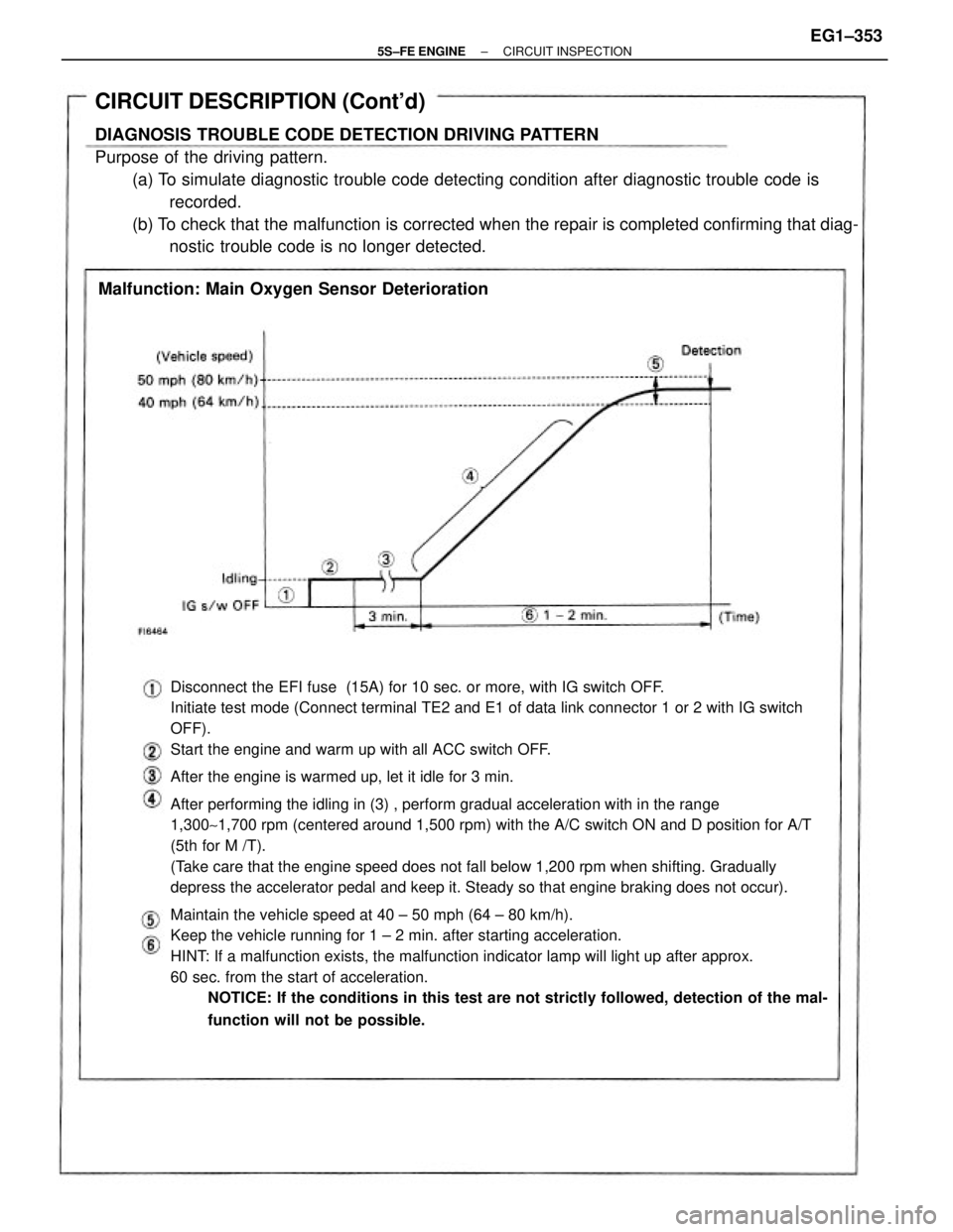
Disconnect the EFI fuse (15A) for 10 sec. or more, with IG switch OFF.
Initiate test mode (Connect terminal TE2 and E1 of data link connector 1 or 2 with IG switch
OFF).
Start the engine and warm up with all ACC switch OFF.
After the engine is warmed up, let it idle for 3 min.
After performing the idling in (3) , perform gradual acceleration with in the range
1,300~1,700 rpm (centered around 1,500 rpm) with the A/C switch ON and D position for A/T
(5th for M /T).
(Take care that the engine speed does not fall below 1,200 rpm when shifting. Gradually
depress the accelerator pedal and keep it. Steady so that engine braking does not occur).
Maintain the vehicle speed at 40 ± 50 mph (64 ± 80 km/h).
Keep the vehicle running for 1 ± 2 min. after starting acceleration.
HINT: If a malfunction exists, the malfunction indicator lamp will light up after approx.
60 sec. from the start of acceleration.
NOTICE: If the conditions in this test are not strictly followed, detection of the mal-
function will not be possible.
CIRCUIT DESCRIPTION (Cont'd)
DIAGNOSIS TROUBLE CODE DETECTION DRIVING PATTERN
Purpose of the driving pattern.
(a) To simulate diagnostic trouble code detecting condition after diagnostic trouble code is
recorded.
(b) To check that the malfunction is corrected when the repair is completed confirming that diag-
nostic trouble code is no longer detected.
Malfunction: Main Oxygen Sensor Deterioration
± 5S±FE ENGINECIRCUIT INSPECTIONEG1±353
Page 407 of 4770
DIAGNOSTIC CHART
HINT If diagnostic trouble codes ª22º (engine coolant temperature sensor circuit), ª24º (intake air temperature sensor cir-
cuit), ª31º (manifold absolute pressure sensor circuit) and ª41º (throttle position sensor circuit) are output simultaneously, E2
(sensor ground) may be open, OK Check for momentary interruption
Check for open and short in harness and connector
between ECM and engine coolant temp. sensor.Check for momentary interruption
(See page EG1±309).
Repair or replace harness or
connector.Replace engine coolant temp. sensor.
WIRING DIAGRAM
Check resistance of sensor.
Check and replace ECM.Check voltage of sensor.
± 5S±FE ENGINECIRCUIT INSPECTIONEG1±357
Page 408 of 4770
INSPECTION PROCEDURE
HINT: If diagnostic trouble codes ª22º (engine coolant temperature sensor circuit), ª24º (intake air
temperature sensor circuit), ª31º (manifold absolute pressure sensor circuit) and ª41 ª (throttle
position sensor circuit) are output simultaneously, E2 (sensor ground) may be open,
(1) Remove glove compartment
(See page EG1±234)
(2) Turn ignition switch on.
Measure voltage between terminals THW and E2 of engine
control module connector.
Check voltage between terminals THW and E2 of engine control
module connector.
Check for momentary interruption
(See page EG1±309)
Engine Coolant Temp. �C (�F)
20 (68)
( Engine is cool )
80 (176)
(Engine is hot)0.2 ~1.0 v 0.5 ~ 3.4 V Voltage
± 5S±FE ENGINECIRCUIT INSPECTIONEG1±358
Page 409 of 4770
Check for open and short in harness and connector between engine
control module and engine coolant temp. sensor (See page IN±31).
Disconnect the engine coolant temp. sensor con±
nector.
Measure resistance between terminals.
Resistance is within Acceptable Zone on chart.
Check engine coolant temp. sensor.
Check and replace engine control module.Repair or replace harness or connector.Replace engine coolant temp. sensor.
Engine coolant
Temp. �C (�F)
0.2 ± 0.4 k� Resistance
80(176)20(68)
2 ± 3 k�
± 5S±FE ENGINECIRCUIT INSPECTIONEG1±359