Page 351 of 4770
If a malfunction code is displayed during the diagnostic trouble code check in test mode, check the circuit
for that code listed in the table below (Proceed to the page given for that circuit).
wOpen or short in IGF or IGT circuit from igniter to ECM
wIgniter
wECM wOpen or short in NE, G circuit
wDistributor
wOpen or short in STA circuit
9 ECM
wOpen or short in NE circuit
wDistributor
wECM
Malfunction
Indicator
Lamp*�
*�,*�: See page EG1±306Normal
Mode Trouble Area
Memory*�
Test
ModeSee page
EG1±351EG1±339
wECM
E G ±343 EG1±336
EG1±344 N.A.
N.A.N.A.
N.A. N.A.
N.A.N.A.
± 5S±FE ENGINEDIAGNOSTIC TROUBLE CODE CHARTEG1±301
Page 356 of 4770

*1; ªONº displayed in the diagnosis mode column indicates that the Malfunction Indicator Lamp is lighted up when a
malfunction is detected. ªOFFº indicates that the ªCHECKº does not light up during malfunction diagnosis, even if a
malfunction is detected. ªN.A.º indicates that the item is not included in malfunction diagnosis.
*2; ªOº in the memory column indicates that a diagnostic trouble code is recorded in the ECM memory when a malfunction
occurs. ªXº indicates that a diagnostic trouble code is not recorded in the ECM memory even if a malfunction occurs.
Accordingly, output of diagnostic results in normal or test mode is performed with the IG switch ON.
*3; Only for California specification vehicles.
*4; Only vehicles with A/T.EGR gas temp. is 70�C (158�F) or below for 50 sec. under
conditions (a) and (b).
(2 trip detection logic)*�
(a) Engine coolant temp.: 80�C (176�F) or more.
(b) EGR operation possible (Ex. A/T in 3rd speed (5th for
M/T), 55 ± 60 mph (88 ± 96 km/h), Flat road).
(1) 3 sec. or more after engine starts with closed throttle position
switch OFF (IDL).
(2) *� Park/Neutral switch OFF (PNP).
(Shift position in ªRº, ªDº, ª2º, or ªLº positions).
(3) A/C switch ON. Open or short in knock sensor circuit with engine speed
between 1,200 rpm and 6,000 rpm.Diagnostic trouble Code
Detecting Condition
Switch Condition
SignalNo starter signal to ECM.
Knock Sensor
Signal
EG R System
Malfunction Number of
MIL Blinks
Starter Signal DTC
No.Circuit
± 5S±FE ENGINEDIAGNOSTIC TROUBLE CODE CHARTEG1±306
Page 359 of 4770

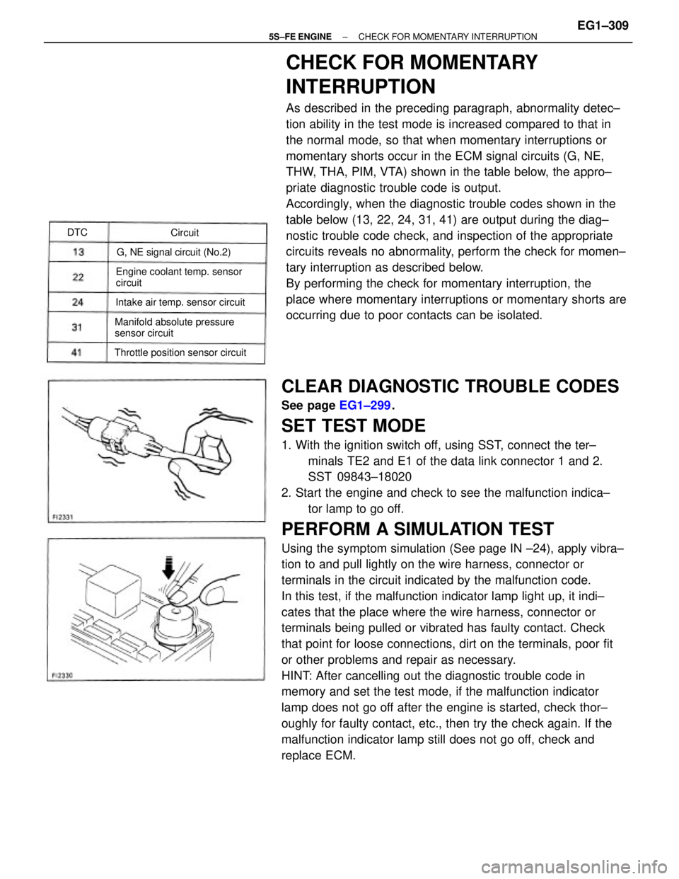
CLEAR DIAGNOSTIC TROUBLE CODES
See page EG1±299.
SET TEST MODE
1. With the ignition switch off, using SST, connect the ter±
minals TE2 and E1 of the data link connector 1 and 2.
SST 09843±18020
2. Start the engine and check to see the malfunction indica±
tor lamp to go off.
PERFORM A SIMULATION TEST
Using the symptom simulation (See page IN ±24), apply vibra±
tion to and pull lightly on the wire harness, connector or
terminals in the circuit indicated by the malfunction code.
In this test, if the malfunction indicator lamp light up, it indi±
cates that the place where the wire harness, connector or
terminals being pulled or vibrated has faulty contact. Check
that point for loose connections, dirt on the terminals, poor fit
or other problems and repair as necessary.
HINT: After cancelling out the diagnostic trouble code in
memory and set the test mode, if the malfunction indicator
lamp does not go off after the engine is started, check thor±
oughly for faulty contact, etc., then try the check again. If the
malfunction indicator lamp still does not go off, check and
replace ECM.
CHECK FOR MOMENTARY
INTERRUPTION
As described in the preceding paragraph, abnormality detec±
tion ability in the test mode is increased compared to that in
the normal mode, so that when momentary interruptions or
momentary shorts occur in the ECM signal circuits (G, NE,
THW, THA, PIM, VTA) shown in the table below, the appro±
priate diagnostic trouble code is output.
Accordingly, when the diagnostic trouble codes shown in the
table below (13, 22, 24, 31, 41) are output during the diag±
nostic trouble code check, and inspection of the appropriate
circuits reveals no abnormality, perform the check for momen±
tary interruption as described below.
By performing the check for momentary interruption, the
place where momentary interruptions or momentary shorts are
occurring due to poor contacts can be isolated.
Engine coolant temp. sensor
circuit
Manifold absolute pressure
sensor circuit
Throttle position sensor circuitIntake air temp. sensor circuitG, NE signal circuit (No.2)Circuit DTC
± 5S±FE ENGINECHECK FOR MOMENTARY INTERRUPTIONEG1±309
Page 360 of 4770
BASIC INSPECTION
When the normal code is displayed in the diagnostic trouble code check, troubleshooting should be
performed in the order for all possible circuits to be considered as the causes of the problems.
In many cases, by carrying out the basic engine check shown in the following flow chart, the location
causing the problem can be found quickly and efficiently. Therefore, use of this check is essential in en-
gine troubleshooting.
Remove air filter.
Visually check that the air filter is not excessively
damaged or oily.
If necessary, clean the air filter with compressed
air. First blow from inside thoroughly, then blow
off outside of the air filter.
Is battery positive voltage 11 V or more when engine is stopped?
Proceed to matrix chart of problem
symptoms on page EG1±327.
Is engine cranked ?
Does engine start
Charge or replace battery.
Check air filter.
Repair or replace. Go to step
Go to step
YESYES
YES
± 5S±FE ENGINEBASIC INSPECTIONEG1±310
Page 361 of 4770

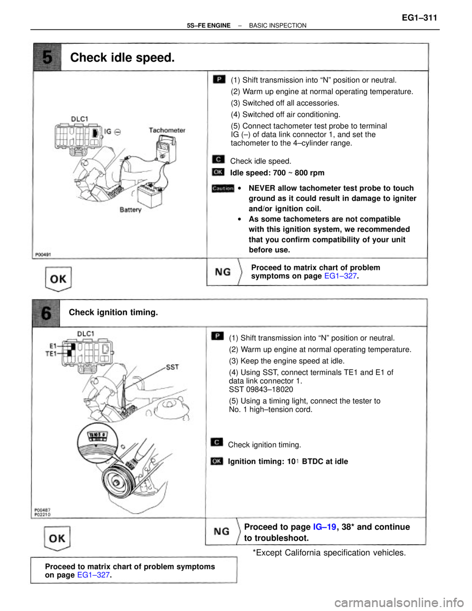
(1) Shift transmission into ªNº position or neutral.
(2) Warm up engine at normal operating temperature.
(3) Keep the engine speed at idle.
(4) Using SST, connect terminals TE1 and E1 of
data link connector 1.
SST 09843±18020
(5) Using a timing light, connect the tester to
No. 1 high±tension cord.(1) Shift transmission into ªNº position or neutral.
(2) Warm up engine at normal operating temperature.
(3) Switched off all accessories.
(4) Switched off air conditioning.
(5) Connect tachometer test probe to terminal
IG (±) of data link connector 1, and set the
tachometer to the 4±cylinder range.
wNEVER allow tachometer test probe to touch
ground as it could result in damage to igniter
and/or ignition coil.
wAs some tachometers are not compatible
with this ignition system, we recommended
that you confirm compatibility of your unit
before use.
Proceed to matrix chart of problem symptoms
on page EG1±327.
Proceed to page IG±19, 38* and continue
to troubleshoot.
Proceed to matrix chart of problem
symptoms on page EG1±327.
*Except California specification vehicles. Check ignition timing.
Check idle speed.
Check idle speed.
Idle speed: 700 ~ 800 rpm
Check ignition timing.
Ignition timing: 10� BTDC at idle
± 5S±FE ENGINEBASIC INSPECTIONEG1±311
Page 362 of 4770
(1) Be sure that fuel is enough in tank.
(2) Turn ignition switch on.
(3) Using SST, connect terminals FP and + B of
data link connector 1.
SST 09843±18020
Check for fuel pressure in the return hose when it
is pinched off.
Disconnect the high±tension cord from the distributor and, hold the end about 12.5 mm (1/2º)
from the ground, see if spark occurs while the engine is being cranked.
To prevent excessive fuel injected from the injectors during this test, don't crank the engine for
more than 1±2 seconds at a time.Never make a mistake with the terminal con±
nection position as this will cause a malfunc±
tion.
Proceed to matrix chart of problem symptoms
on page EG1±327.
Proceed to page EG1±178 and continue
to troubleshoot.
Proceed to page IG±6, 26* and continue
to troubleshoot.
* : Except California specification vehicles.
Check fuel pressure.
Check for spark.
At this time, you will hear fuel return noise.
± 5S±FE ENGINEBASIC INSPECTIONEG1±312
Page 377 of 4770

MATRIX CHART OF PROBLEM SYMPTOMS
When the malfunction code is not confirmed in the diagnostic trouble code check and the problem still can
not be confirmed in the basic inspection, then proceed to this step and perform troubleshooting according
to the numbered order given in the table below.
*: Except California specification vehicles.
Park/Neutral position switch circuitManifold absolute pressure sensor circuit
VSV circuit for fuel pressure control
Ignition signal circuit (Spark test)
After acceleration pedal depressed
After acceleration pedal released
Switch condition signal circuit
Muffler explosion (after fire)No initial combustion
Back up power source circuit
Hesitation/Poor accelerationNo complete combustion
ECM power source circuit
Starter and Starter relay
Engine control module
High engine idle speed
Low engine idle speedUnder normal condition
During A/C operationEngine does not crank
A/C cut control circuit Starter signal circuit
Soon after starting
Fuel system circuit
When N to D shiftIncorrect first idle
Poor
Driveability
IAC valve circuit Difficult to
start
Injector circuit
Rough idling
Does not
start
Compression
Suspect area
Cold engine
Ignition coil Engine Stall
EG R system
Hot engine
Poor Idling
Spark plug
A/T faultylG±10,30*
IG±11,30 Distributor
Symptom
ST±19,21
See page
IG±8,28* IG±6,26*
Hunting
Surging
EG1±400
EG1±410 EG1±390
EG1±403
EG1±408
EG1±415
EG1±419EG1±383EG1±372
EG1±428EG1±396
EG1 ±424
AX1±68 EG1±23
IN±36
± 5S±FE ENGINEMATRIX CHART OF PROBLEM SYMPTOMSEG1±327
Page 386 of 4770
CIRCUIT DESCRIPTION
The distributor in the Engine Control System contains 3 pickup coils.
The G signals inform the ECM of the standard crankshaft position.
The NE signals inform the ECM of the crankshaft position and the engine speed.
wDuring cranking or idling, check waveforms
between terminals G (+) and G (±),
NE (+) and NE (±) of engine control module.
HINT: The correct waveforms appear as shown
in the illustration on the left.
wOpen or short in NE, G circuit
wDistributor
wOpen or short in STA circuit
wECM No G signal to ECM for 3 sec. or more with
engine speed between 600 rpm and 4,000 rpm. No N E signal to ECM with 2 sec. or more after
cranking.
CIRCUIT INSPECTION
INSPECTION USING OSCILLOSCOPE
Diagnostic Trouble Code Detecting Condition
Reference
Trouble Area
DTC 12 G NE Signal Circuit (No.1) (Exc. California spec.)
DTC No.
± 5S±FE ENGINECIRCUIT INSPECTIONEG1±336