Page 398 of 4770
Disconnect igniter connector.
Measure voltage between terminal 3 of igniter
connector and body ground, when ignition
switch is turned to ªONº and ªSTAº position.
Voltage: 9 ~ 14 V
Check for open and short in harness and connector between ignition
switch and ignition coil, ignition coil and igniter (See page IN±31). Check voltage between terminal 3 of igniter connector and body
ground.
Check and repair igniter power source
circuit.
Repair or replace harness or connector.
± 5S±FE ENGINECIRCUIT INSPECTIONEG1±348
Page 399 of 4770
For California spec.
(1) Disconnect ignition coil connector.
(2) Disconnect high±tension cord from ignition
coil.
Exc. California spec.
(1) Disconnect distributor connectors.
(2) Remove distributor cap and rotor.
(3) Remove ignition coil dust cover.
(1) Check primary coil.
Measure resistance between the positive
(+) and negative (±) terminals.
(2) Check secondary coil.
Measure resistance between the positive
(+) and high±tension terminals.
ªColdº is from ±10
�C (14�F) to 50�C (122�F) and
ªHotº is from 50
�C (122�F) to 100�C (212�F).
Check ignition coil.
Replace ignition coil.
Replace igniter.
Secondary
CoilPrimary
CoilResistanceCold
Cold
HotHot
± 5S±FE ENGINECIRCUIT INSPECTIONEG1±349
Page 453 of 4770

CIRCUIT DESCRIPTION
When the ignition switch is turned on, battery positive voltage is applied to the coil, closing the
contacts of the EFI main relay and supplying power to the terminals + B and + 131 of the ECM.
Check for open in harness and connector
between IG switch and EFI main relay, EFI main
relay and body ground.
Check for open in harness and connector
between EFI main relay and battery, EFI main
relay and ECM.Check continuity between terminal E1 and
body ground.Proceed to next circuit inspection shown
on matrix chart (See page EG1±327).
Check for short in all the harness and
components connected to IGN fuse.
Check for short in all the harness and
components connected to EFI fuse.
ECM Power Source Circuit
Repair or replace harness or connector.
Repair or replace harness or connector. Check voltage of ECM power source.
DIAGNOSTIC CHART
Replace ignition switch.
Check EFI fuse.Replace EFI main relay.
Check ignition switch.Check EFI main relay.
Check IGN fuse.
± 5S±FE ENGINECIRCUIT INSPECTIONEG1±403
Page 469 of 4770
CIRCUIT DESCRIPTION
Fuel pump control
The fuel pump is switched on (low voltage at terminal FC) when STA is on or while the NE signal
is input to the ECM.
In the diagram below, when the engine is cranked, current flows from terminal ST of the ignition
switch to the starter relay coil, the starter relay switches on and current flows to coil L1 of the circuit
opening relay. Thus the circuit opening relay switches on, power is supplied to the fuel pump and the
fuel pump operates.
When the STA signal and NE signal are input to the ECM, Tr is turned ON, current flows to coil L2
of the circuit opening relay, the relay switches on and the fuel pump operates.
While the NE signal is generated (engine running), the ECM keeps Tr ON (circuit opening relay ON)
and the fuel pump also keeps operating.
Fuel System Circuit
± 5S±FE ENGINECIRCUIT INSPECTIONEG1±419
Page 509 of 4770

30
ENGINE
5S±FE ENGINE
� DESCRIPTION
The 5S±FE engine has improved the torque in the low±to±mid±speed range through improvements made for the intake
and exhaust systems and the combustion chamber. In addition, its exhaust emissions have been reduced through the
improvements made for the exhaust system and the engine control system.
� ENGINE SPECIFICATIONS AND PERFORMANCE CURVE
5S±FE EngineNewPreviousItemNewPrevious
No. of Cyls. & Arrangement6±Cylinder, In±Lineu
Valve Mechanisms16±Valve DOHC,
Belt & Gear Driveu
Combustion ChamberPentroof Typeu
ManifoldsCross±Flowu
Fuel SystemSFIu
Displacement cm3(cu. in.)2164 (132.0)u
Bore x Stroke mm (in.)87.0 x 91.0 (3.43 x 3.58)u
Compression Ratio9.5 : 1u
Max. Output [SAE±NET]
99 kW @ 5200 rpm
(133 HP @ 5200 rpm)
97 kW @ 5200 rpm*
(130 HP @ 5200 rpm)*
93 kW @ 5400 rpm
(125 HP @ 5400 rpm)
Max. Output [SAE±NET]
199 N.m @ 4400 rpm
(147 ft
.lbf @ 4400 rpm)
197 N
.m @ 4400 rpm*
(145 HP @ 4400 rpm)*
197 N.m @ 4400 rpm
(145 ft
.lbf @ 4400 rpm)
IntakeOpen3o BTDCu
Valve Timing
IntakeClose43o ABDCuValve Timing
ExhaustOpen45o
BBDCuExhaustClose3o
ATDCu
Fuel Octane Number RON91u
Oil GradeAPI SH EC±II, ILDAC or Betteru
*: California Specification Model
Page 514 of 4770
35 ENGINEÐ5S±FE ENGINE
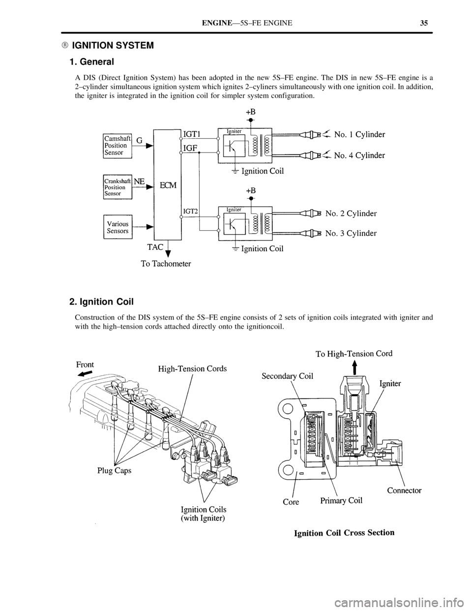
� IGNITION SYSTEM
1. General
A DIS (Direct Ignition System) has been adopted in the new 5S±FE engine. The DIS in new 5S±FE engine is a
2±cylinder simultaneous ignition system which ignites 2±cyliners simultaneously with one ignition coil. In addition,
the igniter is integrated in the ignition coil for simpler system configuration.
2. Ignition Coil
Construction of the DIS system of the 5S±FE engine consists of 2 sets of ignition coils integrated with igniter and
with the high±tension cords attached directly onto the ignitioncoil.
Page 521 of 4770

42ENGINEÐ5S±FE ENGINE
5. Main Components of Engine Control System
The following table compares the main components of the new 5S±FE engine, and previous 5S±FE engine.
Model
NewPreviousComponentNewPrevious
Manifold Absolute Pressure SensorSemiconductoru
Throttle Position SensorLinear Typeu
Crankshaft Position SensorPick±Up Coil Type, 1u
Camshaft Position SensorPick±Up Coil Type, 1Ð
DistributorCamshaft PositionPick Up Coil Type 1DistributorSensorÐPick±Up Coil Type, 1
Knock SensorBuilt±In Piezoelectric
Element Type 1u
Oxygen Sensor
Heated Oxygen Sensor
(Bank 1, Sensor 1)*
1
(Bank 1, Sensor 2)
Air Fuel Ratio Sensor*
2
Oxygen Sensor
(Bank 1, Sensor 1)
(Bank 1, Sensor 2)
Injector2±Hole Typeu
IAC ValveRotary Solenoid Typeu
*1: Except for California Specification Models.
*
2: Only for California Specification Models.
Camshaft Position Sensor
The camshaft position sensor is mounted onto the
cylinder head. Using the protusion that is provided
on the timing pulley, the sensor generates 1 signal
for every revolution. This signal is then sent to the
ECM as a cranskshaft angle system.
Page 523 of 4770

44ENGINEÐ1MZ±FE ENGINE
1MZ±FE ENGINE
� DESCRIPTION
The 1MZ±FE engine has achieved a reduction in exhaust emissions through the adoption of the fuel returnless system
and the changes made onto the EGR control system.
� ENGINE SPECIFICATIONS AND PERFORMANCE CURVE
1MZ±FE EngineNewPreviousItemNewPrevious
No. of Cyls. & Arrangement6±Cylinder, V Typeu
Valve Mechanisms24±Valve DOHC,
Belt & Gear Driveu
Combustion ChamberPentroof Typeu
ManifoldsCross±Flowu
Fuel SystemsSFIu
Displacement cm3(cu. in.)2995 (182.7)u
Bore x Stroke mm (in.)87.5 x 83.0 (3.44 x 3.27)u
Compression Ratio10.5 : 1u
Max. Output {SAE_NET]145 kW @ 5200 rpm
(194 HP @ 5200 rpm)140 kW @ 5200 rpm
(188 HP @ 5200 rpm)
Max. Output {SAE_NET]283 N.m @ 4400 rpm
(209 ft
.lbf @ 4400 rpm)
275 N.m @ 4400 rpm
(203 ft
.lbf @ 4400 rpm)
IntakeOpen4o BTDCu
Valve Timing
IntakeClose44o ABDCuValve Timing
ExhaustOpen46oBBDCuExhaustClose2o
ATDCu
Fuel Octane Number RON91 OR Higheru
Oil GradeAPI SH EC±II, ILDAC or Betteru
Premium unleaded gasoline (96RON) is used for the above specifications.

 Disconnect ignition coil connector.
(2) Disconnect high±tension cord from ignition
coil.
Exc. California spec.
(1) Disconnect distributor connectors.
(2) Remove distributor c")
 when STA is on or while the NE signal
is input to the ECM.
In the diagram below, when the engine is cran")