Page 2860 of 4770

FI0534
S05335
TOYOTA hand±held tester
DLC3
DI±440
± DIAGNOSTICSAUTOMATIC TRANSAXLE (A541E)
675 Author�: Date�:
2. INSPECT DIAGNOSIS (NORMAL MODE)
(a) Check the MIL.
(1) The MIL comes on when the ignition switch is turned
ON and the engine is not running.
HINT:
If the MIL does not light up, troubleshoot the combination meter
(See page BE±2).
(2) When the engine is started, the MIL should go off.
If the lamp remains on, the diagnosis system has
detected a malfunction or abnormality in the sys-
tem.
(b) Check the DTC.
NOTICE:
TOYOTA hand±held tester only:
When the diagnostic system is switched from normal mode
to check mode, it erases all DTCs and freeze frame data re-
corded in normal mode. So before switching modes, al-
ways check the DTCs and freeze frame data, and note them
down.
(1) Prepare an OBD II scan tool (complying with SAE
J1978) or TOYOTA hand±held tester.
(2) Connect the OBD II scan tool or TOYOTA hand±
held tester to DLC3 at the lower of the instrument
panel.
(3) Turn the ignition switch ON and turn the OBD II scan
tool or TOYOTA hand±held tester switch ON.
(4) Use the OBD II scan tool or TOYOTA hand±held
tester to check the DTCs and freeze frame data and
note them down (For operating instructions, see the
OBD II scan tool's instruction book).
(5) See page DI±449 to confirm the details of the DTCs.
NOTICE:
When simulating symptoms with an OBD II scan tool (ex-
cluding TOYOTA hand±held tester) to check the DTCs, use
normal mode. For codes on the DTCs chart subject to º2
trip detection logicº, turn the ignition switch off after the
symptoms have been simulated the 1st time. Them repeat
the simulation process again. When the program has DTCs
are recorded in the ECM.
Page 3225 of 4770

Start
Unlock all doors manually
Insert key in ignition key cylinder and open driver's doorHINT: Diagnostic mode may be exited
at any time by ungrounding terminal 9
Ground terminal 9 of the wireless door lock ECU and
wait more 1 second.
Remove key from ignition key cylinder and close
driver 's door within 10 seconds.
Press any button on transmitter within 10 seconds.If not performing this operation
within 10 seconds after the
above operation, the mode will
not change into the diagnostic
mode.
If not performing this operation
within 10 seconds after the
above operation, the mode will
not change into the diagnostic
mode.
CONTINUED ON NEXT PAGE
± DIAGNOSTICSWIRELESS DOOR LOCK CONTROL SYSTEM
DI±805
1040 Author�: Date�:
(2) A transmitter recognition code is registered by
pressing any single button of the transmitter to be
registered. Once the code is registered, the ECU
responds again by operating once the lock and un-
lock functions of all the doors.
(3) To register the recognition code of an additional
transmitter, follow the procedure shown in (2).
(4) After completing the registration of the codes, re-
move the test lead from the remote control mirror
switch connector terminals to allow the system to
revert to the normal operation.
(5) Using the registered transmitter, verify that the sys-
tem operates properly.
4. DIAGNOSTIC PROCEDURE
Page 3226 of 4770
Does each
door lock
knob oper-
ate?No
Ye sRF (ECU failure) DATA reception
error (Transmitter of ECU failure)
Exit diagnostic mode, and check
transmitter batteries.
If bad, replace batteries and go to
start.
If not starting, replace transmitter and
go to
start.
Door lock motor of all the doors
operate to lock side 1 time. Door lock motor of all the doors
operate to lock side 3 times.
Valid recognition code received
Motor feedback failure
Diagnostic check OK
Check motor feedback for input
line to receiver:
If bad, fix wiring or replace motor.
Other wise, replace receiver and go to start.How does
it opetate?
If still not starting, replace ECU and
go to start.
DI±806
± DIAGNOSTICSWIRELESS DOOR LOCK CONTROL SYSTEM
1041 Author�: Date�:
Page 3248 of 4770

DI1KU±02
DI±828
± DIAGNOSTICSTHEFT DETERRENT SYSTEM
1063 Author�: Date�:
PRE±CHECK
1. Active arming mode:
SETTING THE THEFT DETERRENT MODE
The system will be automatically set to the theft deterrent mode
about 30 seconds after the setting processes listed below are
performed.
Setting Processes: (do processes (1)�(4) in the order)
(1) Remove the ignition key from the key cylinder.
(2) Close all entry points (door, hood and luggage
compartment door).
(3) Use any one of the following methods to lock all the
doors depending on a given condition.
�Use the key to lock the driver or passenger
side door. (as a result, all the doors(including
the engine hood and luggage compartment
door) will be closed and locked), or
�Use the remote control to lock any door (as a
result, all the doors(including the engine
hood and luggage compartment door) will be
closed and locked), or
�If the front right or left door is unlocked when
both the rear doors are already locked, lock
and close the remaining unlocked door by
hand (as a result, all the doors(including the
engine hood and luggage compartment door)
will be closed and locked).
�Close all doors and lock with the engine hood
or luggage compartment door opened, and
close the engine hood or all the doors(includ-
ing the engine hood and luggage compart-
ment door).
(4) About 30 seconds after the above process (3), the
theft deterrent mode will automatically start.
HINT:
The closing/locking of all the entry points (doors, hood and lug-
gage) must remain unchanged for about 30 seconds, the sys-
tem will start the theft deterrent mode.
2. Passive arming mode:
SETTING THE THEFT DETERRENT MODE
The system will be automatically set to the theft deterrent mode
about 30 seconds after the setting processes listed below are
performed.
Setting Processes:
(1) Remove the ignition key from the key cylinder.
(2) Open and close any entry points (door, hood and
luggage compartment door).
Now, all the entry points are closed.
Page 3249 of 4770

I00228
0.25 ± 0.05 sec.
0.25 ± 0.05 sec.
ON
OFF
Horns Sounding and Lights Flashing
Pattern
0.2 ± 0.05 sec.
0.55 ± 0.05 sec. ON
OFF
Output of Key Lock Pattern
± DIAGNOSTICSTHEFT DETERRENT SYSTEM
DI±829
1064 Author�: Date�:
(3) About 30 seconds after the process±(2), on the pre-
vious page the Theft Deterrent mode will automati-
cally start.
HINT:
If, while following above steps, you use the key or the remote
control to lock the door, the system will be set to ACTIVE ARM-
ING MODE.
3. THEFT DETERRENT OPERATION
When the system is set to the theft deterrent mode and any of
the following conditions are met, the system sounds the horns
and flashes the headlights and the taillights for about 1 minute.
At the same time locks all doors (If all doors are not locked at
once, the system repeats door locking operation every 0.55 se-
conds during the one±minute alarm time).
Condition
(1) Any of the doors (Including the engine hood and
luggage compartment door) is unlocked or opened
without the key. *1
(2) The battery terminal is disconnected and recon-
nected. *2
(3) The system receives panic signal from remote key-
less entry. *3
*1: Only active arming mode.
*2: When the ignition key is not inserted in the key
cylinder.
Page 3250 of 4770

I00229
0.75 ± 0.1 sec.
1.25 ± 0.1 sec.
ON
OFF
Blinking Pattern Security only: DI±830
± DIAGNOSTICSTHEFT DETERRENT SYSTEM
1065 Author�: Date�:
4. CANCELLATION OF THEFT DETERRENT OPERA-
TION OR MODE
The theft deterrent operation of mode can be cancelled when
any of the following conditions is met.
No.ConditionCancel of OperationCancel of Mode
1Unlock front doors with the keyEffectiveEffective
2Unlock doors with remote keyless entryEffectiveEffective
3Insert key into ignition key cylinder and turn
it to ACC or ON positionEffectiveEffective
4About 1 minute passes after theft deterrent
operation beginsAutomatic stop *1±
5Unlock the luggage compartment door with
the key or keyless entry.UneffectiveEffective
6Unlock the luggage compartment door with
the keyless entry.UneffectiveEffective
7
If the system receives panic signal again or
unlock signal when the system is activated
by panic signal
Effective *2Uneffective
6If the system receives unlock signal when
the system is activated by panic signalEffectiveEffective
*1: The system is set to the theft deterrent mode again in
about 2 seconds after the operation stops, if all doors are
closed.
*2: The alarm caused by the panic signal malces the sys-
tem in the previous condition.
5. INDICATOR LIGHT (LED)
The indicator light functions as shown below according to the
system condition in the theft deterrent mode. It remains OFF in
the initial state.
System ConditionIndicator Light
During set preparation timeON
When the mode is set*OFF
When alarm is activatedON
When the system is temporally cancelled*OFF
*: The indicator flashes with the output from the immobiliser.
6. KEEPING POWER SUPPLY FUNCTION IN CASE OF
DOME FUSE OPEN
Even if the dome fuse blows open on the theft deterrent mode,
the system will keep working on the theft deterrent mode.
Page 3291 of 4770

BE4032
BE4033I00021
Normal code
0.25 sec.
0.25 sec.
ON
OFF
ON
OFF
4 sec.1.5 sec. 0.5 sec.
2.5 sec.0.5 sec.1.5 sec.
Malfunction codes 11 and 21
Code 11 Code 21
H07517
I08438
DLC1
TC
E1(b) (d) 5 times
within 3 seconds
(c)
± DIAGNOSTICSCRUISE CONTROL SYSTEM
DI±871
1106 Author�: Date�:
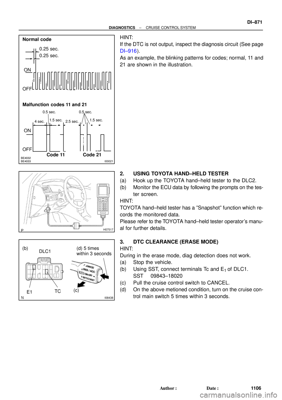
HINT:
If the DTC is not output, inspect the diagnosis circuit (See page
DI±916).
As an example, the blinking patterns for codes; normal, 11 and
21 are shown in the illustration.
2. USING TOYOTA HAND±HELD TESTER
(a) Hook up the TOYOTA hand±held tester to the DLC2.
(b) Monitor the ECU data by following the prompts on the tes-
ter screen.
HINT:
TOYOTA hand±held tester has a ºSnapshotº function which re-
cords the monitored data.
Please refer to the TOYOTA hand±held tester operator's manu-
al for further details.
3. DTC CLEARANCE (ERASE MODE)
HINT:
During in the erase mode, diag detection does not work.
(a) Stop the vehicle.
(b) Using SST, connect terminals Tc and E
1 of DLC1.
SST 09843±18020
(c) Pull the cruise control switch to CANCEL.
(d) On the above metioned condition, turn on the cruise con-
trol main switch 5 times within 3 seconds.
Page 3507 of 4770

EM04I±04
S04994
CO/HC Meter
± ENGINE MECHANICAL (1MZ±FE)CO/HC
EM±1
1287 Author�: Date�:
CO/HC
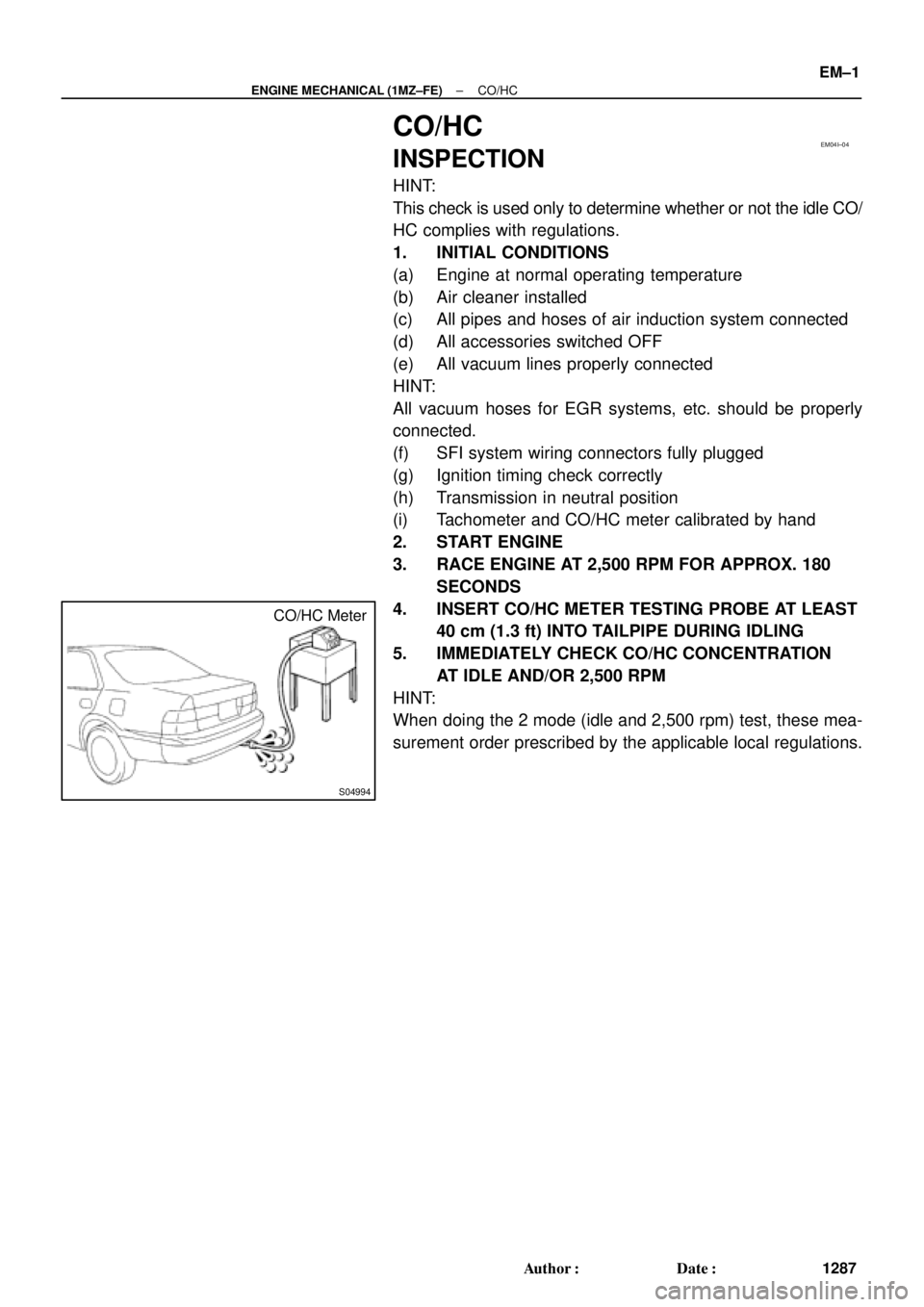
INSPECTION
HINT:
This check is used only to determine whether or not the idle CO/
HC complies with regulations.
1. INITIAL CONDITIONS
(a) Engine at normal operating temperature
(b) Air cleaner installed
(c) All pipes and hoses of air induction system connected
(d) All accessories switched OFF
(e) All vacuum lines properly connected
HINT:
All vacuum hoses for EGR systems, etc. should be properly
connected.
(f) SFI system wiring connectors fully plugged
(g) Ignition timing check correctly
(h) Transmission in neutral position
(i) Tachometer and CO/HC meter calibrated by hand
2. START ENGINE
3. RACE ENGINE AT 2,500 RPM FOR APPROX. 180
SECONDS
4. INSERT CO/HC METER TESTING PROBE AT LEAST
40 cm (1.3 ft) INTO TAILPIPE DURING IDLING
5. IMMEDIATELY CHECK CO/HC CONCENTRATION
AT IDLE AND/OR 2,500 RPM
HINT:
When doing the 2 mode (idle and 2,500 rpm) test, these mea-
surement order prescribed by the applicable local regulations.