Page 4195 of 4770
W03508SST
R13455
10 m (33 ft) or more
R06753
RS±20
± SUPPLEMENTAL RESTRAINT SYSTEMSTEERING WHEEL PAD AND SPIRAL CABLE
2165 Author�: Date�:
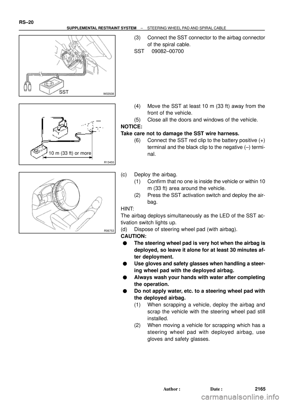
(3) Connect the SST connector to the airbag connector
of the spiral cable.
SST 09082±00700
(4) Move the SST at least 10 m (33 ft) away from the
front of the vehicle.
(5) Close all the doors and windows of the vehicle.
NOTICE:
Take care not to damage the SST wire harness.
(6) Connect the SST red clip to the battery positive (+)
terminal and the black clip to the negative (±) termi-
nal.
(c) Deploy the airbag.
(1) Confirm that no one is inside the vehicle or within 10
m (33 ft) area around the vehicle.
(2) Press the SST activation switch and deploy the air-
bag.
HINT:
The airbag deploys simultaneously as the LED of the SST ac-
tivation switch lights up.
(d) Dispose of steering wheel pad (with airbag).
CAUTION:
�The steering wheel pad is very hot when the airbag is
deployed, so leave it alone for at least 30 minutes af-
ter deployment.
�Use gloves and safety glasses when handling a steer-
ing wheel pad with the deployed airbag.
�Always wash your hands with water after completing
the operation.
�Do not apply water, etc. to a steering wheel pad with
the deployed airbag.
(1) When scrapping a vehicle, deploy the airbag and
scrap the vehicle with the steering wheel pad still
installed.
(2) When moving a vehicle for scrapping which has a
steering wheel pad with deployed airbag, use
gloves and safety glasses.
Page 4207 of 4770
AB0158
SSTBattery
H03287
H08317SST
R13455
10 m (33 ft) or more
H03286
RS±32
± SUPPLEMENTAL RESTRAINT SYSTEMFRONT PASSENGER AIRBAG ASSEMBLY
2177 Author�: Date�:
1. AIRBAG DEPLOYMENT WHEN SCRAPPING VE-
HICLE
HINT:
Have a battery ready as the power source to deploy the airbag.
(a) Check functioning of the SST. (See page RS±18)
SST 09082±00700
(b) Disconnect the airbag connector.
(1) Remove the lower instrument cover inside the No.2
under cover.
NOTICE:
When handling the airbag connector, take care not to dam-
age the airbag wire harness.
(2) Pull up the connector.
(3) Disconnect the airbag connector.
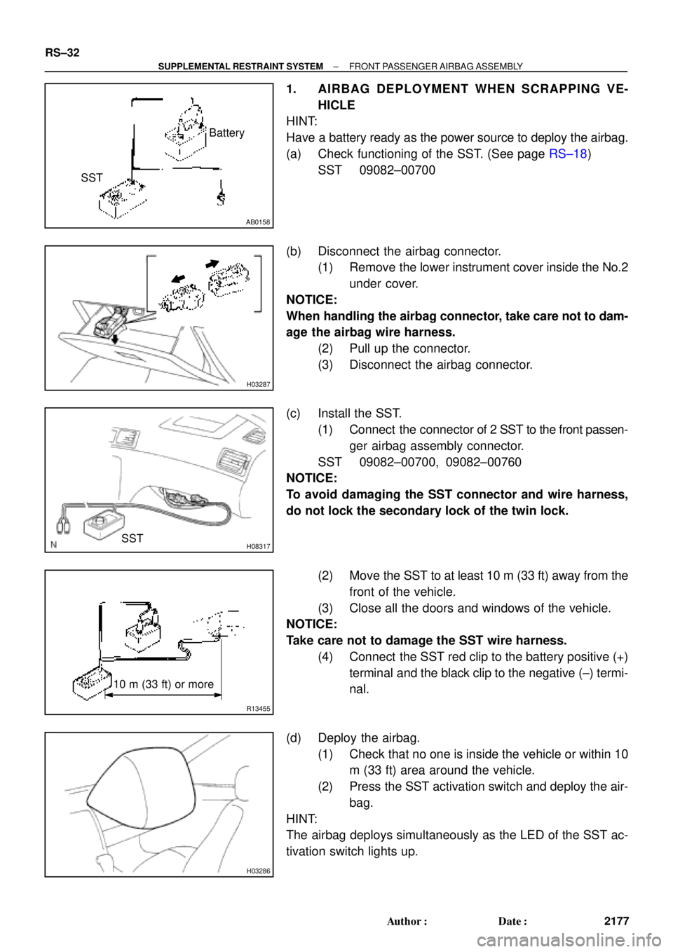
(c) Install the SST.
(1) Connect the connector of 2 SST to the front passen-
ger airbag assembly connector.
SST 09082±00700, 09082±00760
NOTICE:
To avoid damaging the SST connector and wire harness,
do not lock the secondary lock of the twin lock.
(2) Move the SST to at least 10 m (33 ft) away from the
front of the vehicle.
(3) Close all the doors and windows of the vehicle.
NOTICE:
Take care not to damage the SST wire harness.
(4) Connect the SST red clip to the battery positive (+)
terminal and the black clip to the negative (±) termi-
nal.
(d) Deploy the airbag.
(1) Check that no one is inside the vehicle or within 10
m (33 ft) area around the vehicle.
(2) Press the SST activation switch and deploy the air-
bag.
HINT:
The airbag deploys simultaneously as the LED of the SST ac-
tivation switch lights up.
Page 4218 of 4770
AB0158
Battery
SST
H01353
H01354
Battery
SST
R13455
10 m (33 ft) or more
H01326
± SUPPLEMENTAL RESTRAINT SYSTEMSIDE AIRBAG ASSEMBLY (TMC Made)
RS±43
2188 Author�: Date�:
1. AIRBAG DEPLOYMENT WHEN SCRAPPING VE-
HICLE
HINT:
Have a battery ready as the power source to deploy the airbag.
(a) Check functioning of the SST. (See page RS±18)
SST 09082±00700
(b) Disconnect the side airbag connector.
NOTICE:
When handling the airbag connector, take care not to dam-
age the airbag wire harness.
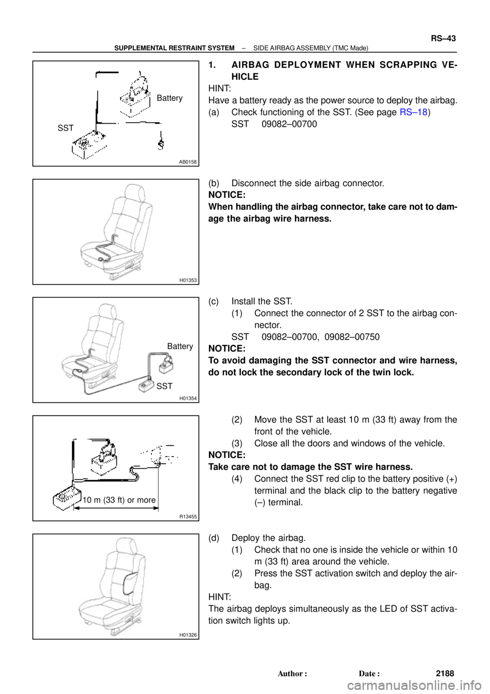
(c) Install the SST.
(1) Connect the connector of 2 SST to the airbag con-
nector.
SST 09082±00700, 09082±00750
NOTICE:
To avoid damaging the SST connector and wire harness,
do not lock the secondary lock of the twin lock.
(2) Move the SST at least 10 m (33 ft) away from the
front of the vehicle.
(3) Close all the doors and windows of the vehicle.
NOTICE:
Take care not to damage the SST wire harness.
(4) Connect the SST red clip to the battery positive (+)
terminal and the black clip to the battery negative
(±) terminal.
(d) Deploy the airbag.
(1) Check that no one is inside the vehicle or within 10
m (33 ft) area around the vehicle.
(2) Press the SST activation switch and deploy the air-
bag.
HINT:
The airbag deploys simultaneously as the LED of SST activa-
tion switch lights up.
Page 4434 of 4770

RS3000 TVIP PROGRAMMING CHANGES FOR GBS ± AX006±99 April 23, 1999
Page 2 of 2
When performing the RS3000 System Test, check the Glass Breakage Sensor sensitivity
as follows:
1. Press and release the Remote Control's top button to arm the system.
2. Wait two seconds.
3. With the tip of the ignition key (or striker tool), softly tap the center of the driver's door
window glass.
�If the system is triggered (horn sounds for 20 seconds), the sensitivity must be
adjusted. Turn the Glass Breakage Sensor ECU's adjustment screw clockwise
one notch, and repeat this step again.
4. If the system is not triggered, repeat the glass tapping with moderate force.
�The system should trigger when the glass is tapped with moderate force. If it is
not triggered, turn the Glass Breakage Sensor ECU's adjustment screw clockwise
one notch, and repeat this step again.
CAUTION:
Use caution when performing the step above. Do not tap the window glass with too
much force, or the glass may crack or break. Use extra caution when the temperature
is extremely cold.
NOTE:
The Owner's Guide included in the RS3000 Base Kit is changed to reflect the
(GBS logic) improvement. There is no change to the GBS ECU itself. Repair
Procedure
Page 4453 of 4770
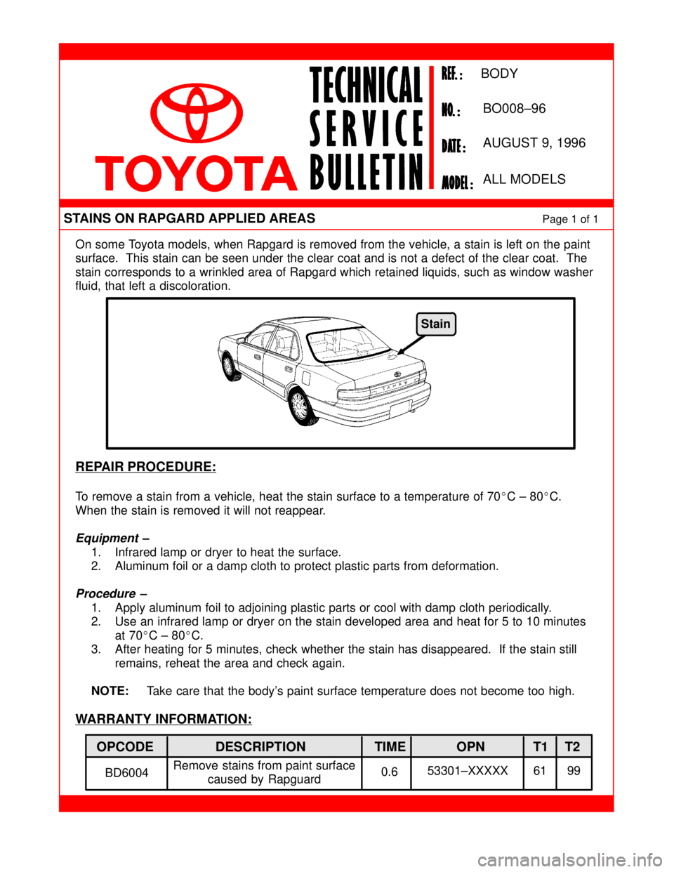
On some Toyota models, when Rapgard is removed from the vehicle, a stain is left on the paint
surface. This stain can be seen under the clear coat and is not a defect of the clear coat. The
stain corresponds to a wrinkled area of Rapgard which retained liquids, such as window washer
fluid, that left a discoloration.
REPAIR PROCEDURE:
To remove a stain from a vehicle, heat the stain surface to a temperature of 70�C ± 80�C.
When the stain is removed it will not reappear.
Equipment ±
1. Infrared lamp or dryer to heat the surface.
2. Aluminum foil or a damp cloth to protect plastic parts from deformation.
Procedure ±
1. Apply aluminum foil to adjoining plastic parts or cool with damp cloth periodically.
2. Use an infrared lamp or dryer on the stain developed area and heat for 5 to 10 minutes
at 70�C ± 80�C.
3. After heating for 5 minutes, check whether the stain has disappeared. If the stain still
remains, reheat the area and check again.
NOTE:Take care that the body's paint surface temperature does not become too high.
WARRANTY INFORMATION:
STAINS ON RAPGARD APPLIED AREASPage 1 of 1
AUGUST 9, 1996
BODY
BO008±96
ALL MODELS
OPCODE DESCRIPTION TIME OPN T1 T2
BD6004Remove stains from paint surface
caused by Rapguard0.653301±XXXXX 61 99
Stain
Page 4469 of 4770
Toyota Supports ASE CertificationPage 1 of 2
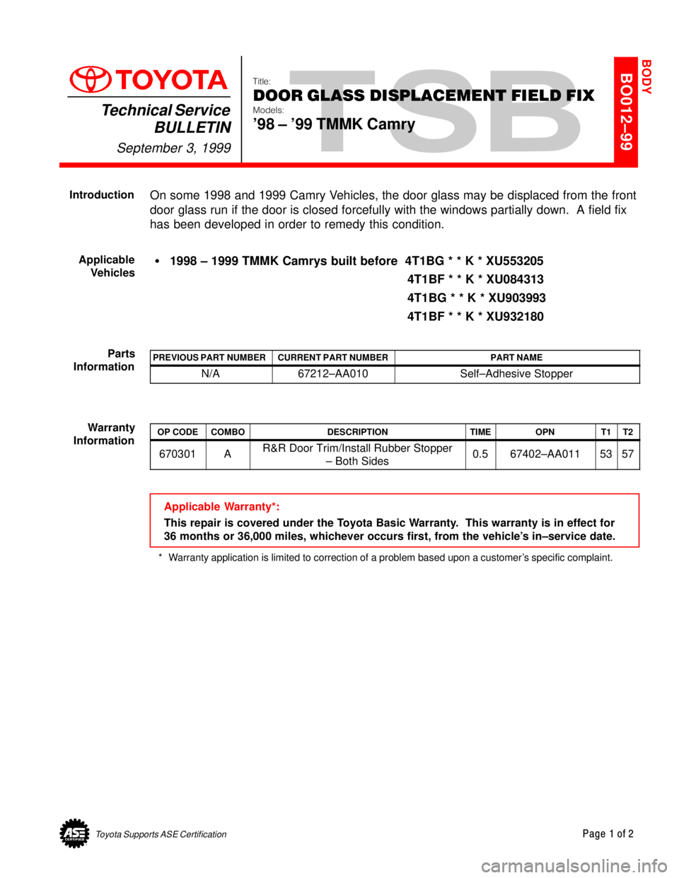
BO012±99
Title:
DOOR GLASS DISPLACEMENT FIELD FIX
Models:
'98 ± '99 TMMK Camry
Technical Service
BULLETIN
September 3, 1999
On some 1998 and 1999 Camry Vehicles, the door glass may be displaced from the front
door glass run if the door is closed forcefully with the windows partially down. A field fix
has been developed in order to remedy this condition.
�1998 ± 1999 TMMK Camrys built before 4T1BG * * K * XU553205
4T1BF * * K * XU084313
4T1BG * * K * XU903993
4T1BF * * K * XU932180
PREVIOUS PART NUMBERCURRENT PART NUMBERPART NAME
N/A67212±AA010Self±Adhesive Stopper
OP CODECOMBODESCRIPTIONTIMEOPNT1T2
670301AR&R Door Trim/Install Rubber Stopper
± Both Sides0.567402±AA0115357
Applicable Warranty*:
This repair is covered under the Toyota Basic Warranty. This warranty is in effect for
36 months or 36,000 miles, whichever occurs first, from the vehicle's in±service date.
* Warranty application is limited to correction of a problem based upon a customer's specific complaint.
BODY
Introduction
Applicable
Vehicles
Parts
Information
Warranty
Information
Page 4470 of 4770
DOOR GLASS DISPLACEMENT FIELD FIX ± BO012±99 September 3, 1999
Page 2 of 2
Refer to 1998 Camry Repair Manual (Vol. 2) Pages BO±11±14.
1. Remove the front door trim to gain access to the window components.
2. Inspect the front and rear lower frames and the door glass run for damage as a result
of the glass being displaced.
�In cases of slight deformation of window frames, reform as necessary.
If significantly deformed or damaged, replace the frame.
�Replace the window run if cut, torn, mutilated, etc.
3. Replace any damaged parts.
4. Remove front lower frame from the door and attach the self±adhesive rubber stopper
(P/N 67212±AA010) 120 mm from the top of the frame as shown below.
NOTE:
To insure proper adhesion of the self±adhesive rubber stopper, the surface of the
frame must be cleaned to remove any foreign material.
5. Reinstall the front lower frame, door glass run, and door trim.
Stopper
67212±AA010
(50 x 12 x 4.76 mm)
(double sided tape)
120 mm
Repair
Procedure
Page 4476 of 4770
Toyota Supports ASE CertificationPage 1 of 2
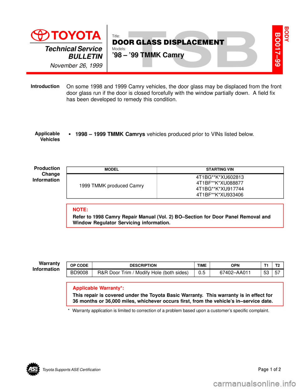
BO017±99
Title:
DOOR GLASS DISPLACEMENT
Models:
'98 ± '99 TMMK Camry
Technical Service
BULLETIN
November 26, 1999
On some 1998 and 1999 Camry vehicles, the door glass may be displaced from the front
door glass run if the door is closed forcefully with the window partially down. A field fix
has been developed to remedy this condition.
�1998 ± 1999 TMMK Camrys vehicles produced prior to VINs listed below.
MODELSTARTING VIN
1999 TMMK produced Camry
4T1BG**K*XU602813
4T1BF**K*XU088877
4T1BG**K*XU917744
4T1BF**K*XU933406
NOTE:
Refer to 1998 Camry Repair Manual (Vol. 2) BO±Section for Door Panel Removal and
Window Regulator Servicing information.
OP CODEDESCRIPTIONTIMEOPNT1T2
BD9008R&R Door Trim / Modify Hole (both sides)0.567402±AA0115357
Applicable Warranty*:
This repair is covered under the Toyota Basic Warranty. This warranty is in effect for
36 months or 36,000 miles, whichever occurs first, from the vehicle's in±service date.
* Warranty application is limited to correction of a problem based upon a customer's specific complaint.
BODY
Introduction
Applicable
Vehicles
Production
Change
Information
Warranty
Information