Page 2009 of 4770

BO0LS±01
N21020
3 Clips
1 Clip
N22588
N21021
4 Clips
N21121
N20985
BO±50
± BODYBACK WINDOW GLASS
2398 Author�: Date�:
REMOVAL
1. REMOVE REAR SEAT CUSHION AND SEATBACKS
2. REMOVE ROOF SIDE INNER GARNISHES
(a) Remove the clips.
(b) Pull the garnish to remove it.
3. REMOVE HIGH±MOUNTED STOP LIGHT
(a) Push on the both side of the cover to release the claws by
your hand and remove the cover as shown in the illustra-
tion.
(b) Remove the 2 bolts and stop light, then disconnect the
connector.
4. REMOVE PACKAGE TRAY TRIM
(a) Remove the bolts holding the rear seat belt lower side to
the body.
(b) Remove the seat belts with seat belt hole covers from the
package trim.
(c) Remove the trim by pulling forward.
5. REMOVE ROOM PARTITION TRIMS
Remove the 6 clips and room partition trims.
6. REMOVE THESE PARTS
(a) Assist grips.
(b) Rear side of roof headlining.
7. DISCONNECT DEFOGGER WIRE CONNECTORS
8. REMOVE BACK WINDOW MOULDING
Using a knife, cut off the moulding as shown.
NOTICE:
Do not damage the body with the knife.
9. REMOVE BACK WINDOW GLASS
Remove the glass in the same way as windshield.
(See page BO±43)
Page 2010 of 4770
BO0LT±01
N21122
BO3671AdhesiveAdhesive
N20986
± BODYBACK WINDOW GLASS
BO±51
2399 Author�: Date�:
INSTALLATION
HINT:
Refer to the installation of windshield, install back window glass
by the following operations.
(See page BO±45)
1. CLEAN AND SHAPE CONTACT SURFACE OF BODY
2. CLEAN REMOVED GLASS
3. REPLACE STOPPERS
4. POSITION GLASS
5. CLEAN CONTACT SURFACE OF GLASS
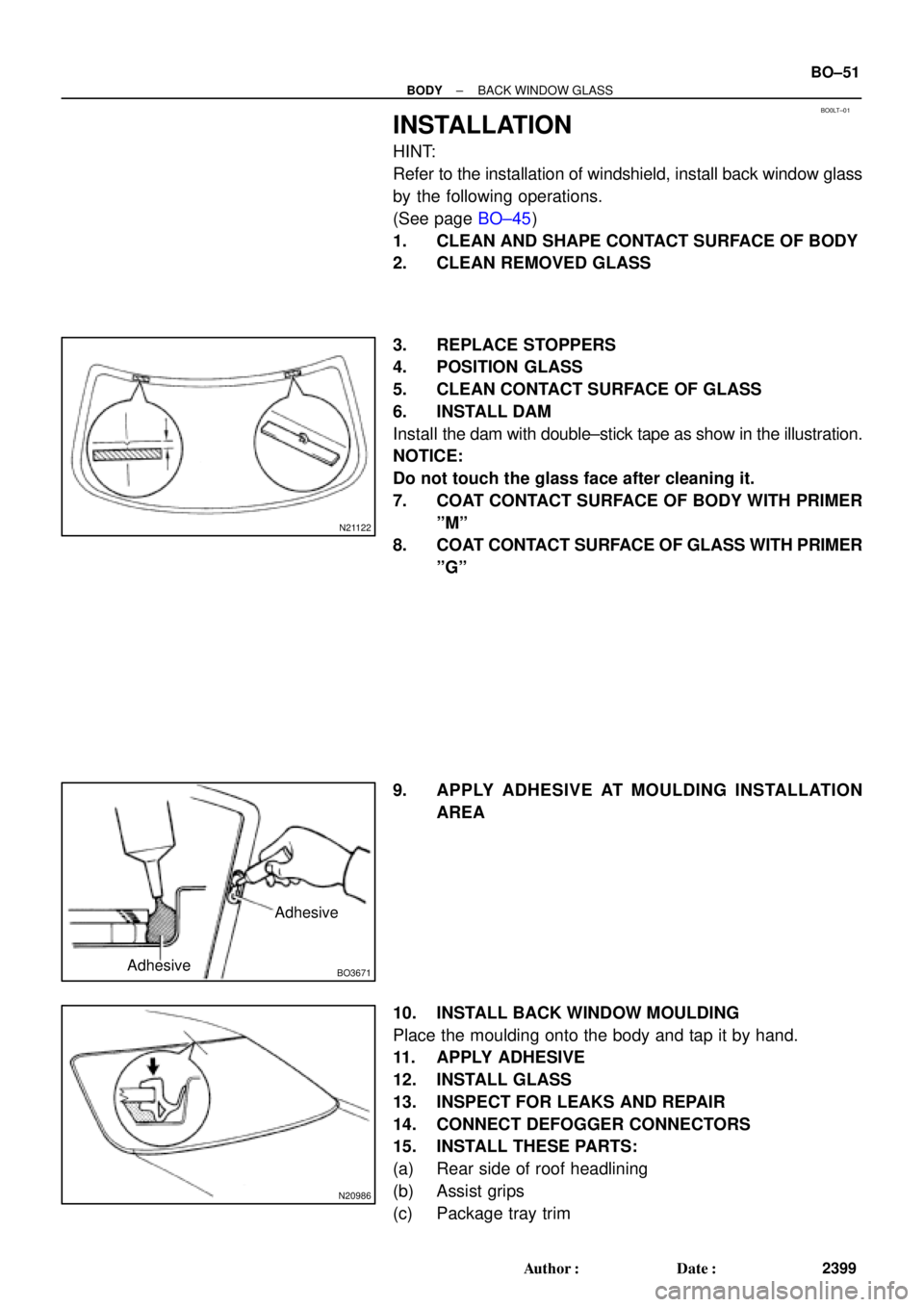
6. INSTALL DAM
Install the dam with double±stick tape as show in the illustration.
NOTICE:
Do not touch the glass face after cleaning it.
7. COAT CONTACT SURFACE OF BODY WITH PRIMER
ºMº
8. COAT CONTACT SURFACE OF GLASS WITH PRIMER
ºGº
9. APPLY ADHESIVE AT MOULDING INSTALLATION
AREA
10. INSTALL BACK WINDOW MOULDING
Place the moulding onto the body and tap it by hand.
11. APPLY ADHESIVE
12. INSTALL GLASS
13. INSPECT FOR LEAKS AND REPAIR
14. CONNECT DEFOGGER CONNECTORS
15. INSTALL THESE PARTS:
(a) Rear side of roof headlining
(b) Assist grips
(c) Package tray trim
Page 2011 of 4770
BO±52
± BODYBACK WINDOW GLASS
2400 Author�: Date�:
(d) Room partition trims
(e) Seat belt lower side bolts
Torque: 42 N´m (420 kgf´cm, 31 ft´lbf)
(f) High±mounted stop light
(g) Roof side inner garnish
(h) Rear seatbacks and seat cushion
Torque: 18 N´m (185 kgf´cm, 13 ft´lbf)
Page 2013 of 4770
BO0M2±01
N22654
Side Garnish
Sliding Roof Glass
Rear Roof
Drip Channel
Roof Window
Deflector Panel
Side Garnish
Drive Cable
Guide Block
Guide Block
Sliding Roof
Housing
Drive Gear
Sunshade Trim
Sliding Roof
Panel Stopper Guide Rail Stopper
Roof Rail
Rear Frame
5.5 (55, 49 in.´lbf)N´m (kgf´cm, ft´lbf): Specified torque BO±54
± BODYSLIDING ROOF (TMC Made)
2402 Author�: Date�:
COMPONENTS
Page 2016 of 4770
BO0M4±01
N21523
N21421
N21424
N21526
N21525
± BODYSLIDING ROOF (TMC Made)
BO±57
2405 Author�: Date�:
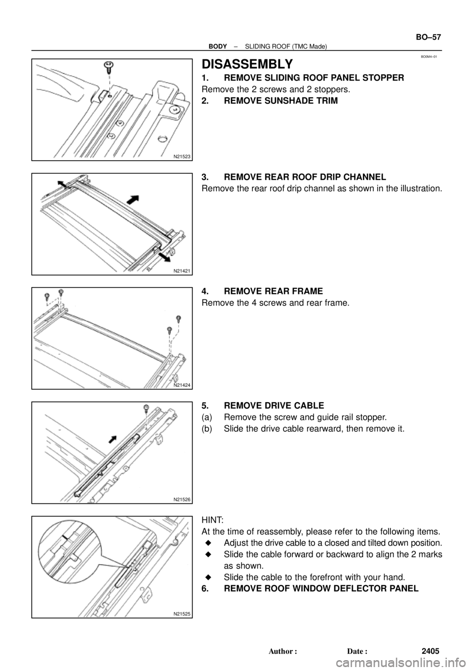
DISASSEMBLY
1. REMOVE SLIDING ROOF PANEL STOPPER
Remove the 2 screws and 2 stoppers.
2. REMOVE SUNSHADE TRIM
3. REMOVE REAR ROOF DRIP CHANNEL
Remove the rear roof drip channel as shown in the illustration.
4. REMOVE REAR FRAME
Remove the 4 screws and rear frame.
5. REMOVE DRIVE CABLE
(a) Remove the screw and guide rail stopper.
(b) Slide the drive cable rearward, then remove it.
HINT:
At the time of reassembly, please refer to the following items.
�Adjust the drive cable to a closed and tilted down position.
�Slide the cable forward or backward to align the 2 marks
as shown.
�Slide the cable to the forefront with your hand.
6. REMOVE ROOF WINDOW DEFLECTOR PANEL
Page 2090 of 4770
 or more BO±130
± BODYSEAT BELT PRETENSIONER
2478 Author�: Date�:
(5) Connect the 2 SST, then connect them to the seat
belt pretensioner.
SST 09082±00700, 09082±0")
H01880
SST SST
R13455
10 m (33 ft) or more BO±130
± BODYSEAT BELT PRETENSIONER
2478 Author�: Date�:
(5) Connect the 2 SST, then connect them to the seat
belt pretensioner.
SST 09082±00700, 09082±00740
NOTICE:
To avoid damaging the SST connector and wire harness,
do not lock the secondary lock of secondary lock of the
twin lock.
(6) Move the SST to at least 10mm (33 ft) from the front
of the vehicle.
(7) Close all the doors and windows of the vehicle.
NOTICE:
Take care not to damage the SST wire harness.
(8) Connect the SST red clip the battery positive (±) ter-
minal and the black clip to the negative (+) terminal.
(c) Deploy the airbag.
(1) Confirm that no one is inside the vehicle or within 10
m (33 ft) area around of the vehicle.
(2) Press the SST activation switch and activate the
seat belt pretensioner.
HINT:
The seat belt pretensioner operates simultaneously as the LED
of the SST activation switch light up.
(d) Disposal of front seat outer belt (with seat belt pretension-
er).
CAUTION:
�The front seat outer belt is very hot when the seat belt
pretensioner is deployed, so leave it alone for at least
30 minutes after deployment.
�Use gloves and safety glasses when handling a front
seat outer belt with deployed seat belt pretensioner.
�Always wash your hands with water after completing
the operation.
�Do not apply water, etc. to a front seat outer belt with
deployed seat belt pretensioner.
When scrapping a vehicle, activate the seat belt preten-
sioner and scrap the vehicle with operated front seat out-
er belt still installed.
Page 2102 of 4770

(A541E)
4. Wire Harne")
BE±8
± BODY ELECTRICALBODY ELECTRICAL SYSTEM
2228 Author�: Date�:
Shift indicator lights do not light up.
1. Bulb
2. Meter Circuit Plate
3. Park/Neutral Position Switch (A140E)
(A541E)
4. Wire Harness±
BE±46
DI±424
DI±479
±
Only one shift indicator does not light up.1. Bulb
2. Meter Circuit Plate±
BE±46
Malfunction indicator light does not light up.
1. Bulb
2. ECM
3. Meter Circuit Plate
4. Wire Harness±
±
BE±46
±
SLIP indicator light does not light up.
1. Bulb
2. Traction ECU
3. Meter Circuit Plate
4. Wire Harness±
±
BE±46
±
TRAC OFF indicator light does not light up.
1. Bulb
2. Traction ECU
3. Meter Circuit Plate
4. Wire Harness±
±
BE±46
±
Security indicator light does not light up.
1. Bulb
2. Security ECU
3. Meter Circuit Plate
4. Wire Harness±
±
BE±46
±
Indicator lights do not light up. (Except Turn, Hi±beam and
security)1. GAUGE Fuse (I/P J/B No.1)
2. Wire Harness±
±
DEFOGGER SYSTEM
SymptomSuspect AreaSee page
All defogger systems do not operate.
1. DEFOG M±Fuse (I/P J/B No.1)
2. HTR Fuse (I/P J/B No.1)
3. Defogger Relay (I/P J/B No.1)
4. Defogger Switch
5. Wire Harness±
±
BE±56
BE±56
±
Rear window defogger does not operate.
1. Defogger Wire
2. Choke Coil
3. Wire HarnessBE±56
±
±
Mirror defogger does not operate.
1. MIR/HTR Fuse (I/P J/B No.1)
2. Mirror Defogger
3. Wire Harness±
BE±56
±
POWER WINDOW CONTROL SYSTEM
SymptomSuspect AreaSee page
Power window does not operate (ALL).
(Power Door Lock does not operate)1. POWER M±Fuse (I/P J/B No.1)
2. Power Main Relay (I/P J/B No.1)
3. Wire Harness±
BE±60
±
Power window does not operate (ALL).
(Power Door Lock is normal)1. Ignition Switch
2. Power Window Master Switch
3. Wire HarnessBE±14
BE±60
±
ºOne Touch Power Window Systemº does not operate.1. Power Window Master SwitchBE±60
Only one window glass does not move.
1. Power Window Master Switch
2. Power Window Switch
3. Power Window Motor
4. Wire HarnessBE±60
BE±60
BE±60
±
ºWindow Lock Systemº does not operate.1. Power Window Master SwitchBE±60
Page 2103 of 4770

± BODY ELECTRICALBODY ELECTRICAL SYSTEM
BE±9
2229 Author�: Date�:
ºWindow Lock Illuminationº does not light up.1. Power Window Master SwitchBE±60
Key±off power window does not operate.
1. GAUGE Fuse (I/P J/B No.1)
2. Integration Relay (I/P J/B No.1)
3. Ignition Switch
4. Door Courtesy Switch
5. Wire Harness±
BE±60
BE±14
BE±32
±
POWER DOOR LOCK CONTROL SYSTEM
SymptomSuspect AreaSee page
ºDoor lock systemº does not operate at all.
1. POWER M±Fuse (I/P J/B No.1)
2. CIG Fuse (I/P J/B No.1)
3. DOOR Fuse (I/P J/B No.1)
4. Integration Relay (I/P J/B No.1)
5. Wire Harness±
±
±
BE±70
±
Door lock system does not operate by manual switch.
1. Power Window Master Switch
2. Door Lock Manual Switch
3. Integration Relay (I/P J/B No.1)
4. Wire HarnessBE±60
BE±70
BE±70
±
Door lock system does not operate by door key.
1. Door Key Lock and Unlock Switch
2. Integration Relay (I/P J/B No.1)
3. Wire Harness
4. Door Lock Link DisconnectedBE±70
BE±70
±
±
Fault in 2±Operation unlock function of Driver's side door key lock
and unlock switch.1. Door Key Lock and Unlock Switch
2. Integration Relay (I/P J/B No.1)
3. Wire HarnessBE±70
BE±70
±
Fault in key confine prevention operate.
1. Integration Relay (I/P J/B No.1)
2. Key Unlock Warning Switch
3. Door Courtesy Switch
4. Wire HarnessBE±70
BE±14
BE±32
±
Only one door lock does not operate.1. Door Lock Motor
2. Wire HarnessBE±70
±
SLIDING ROOF SYSTEM
SymptomSuspect AreaSee page
Sliding roof system does not operate.
(Door Lock does not operate)1. POWER M±Fuse (I/P J/B No.1)
2. Power Main Relay (I/P J/B No.1)
3. Wire Harness±
BE±60
±
Sliding roof system does not operate.
(Door Lock is normal)
1. Ignition Switch
2. Sliding Roof Control Relay and Switch
3. Sliding Roof Motor and Limit Switch
4. Wire HarnessBE±14
BE±74
BE±74
±
Sliding roof system operates abnormally.
1. Sliding Roof Control Relay and Switch
2. Sliding Roof Motor and Limit Switch
3. Wire HarnessBE±74
BE±74
±
Sliding roof system stops operation half way.
(Stones of foreign material trapped in motor assembly)1. Sliding Roof Control Relay and Switch
2. Sliding Roof Motor and Limit Switch
3. Wire HarnessBE±74
BE±74
±
ºKey±off Sliding Roofº operation does not operate.
1. DOME Fuse (E/G Room J/B No.2)
2. GAUGE Fuse (I/P J/B No.1)
3. Ignition Switch
4. Integration Relay (I/P J/B No.1)
5. Wire Harness±
±
BE±14
BE±14
±