Page 4347 of 4770

SA07A±01
SA3213
AB
C D
Front
W03090
± SUSPENSION AND AXLEREAR WHEEL ALIGNMENT
SA±7
1958 Author�: Date�:
REAR WHEEL ALIGNMENT
INSPECTION
1. MEASURE VEHICLE HEIGHT
Vehicle height: See page SA±4
NOTICE:
Before inspecting the wheel alignment, adjust the vehicle
height to specification.
2. INSTALL CAMBER ± CASTER ± KINGPIN GAUGE
ONTO VEHICLE OR POSITION VEHICLE ON WHEEL
ALIGNMENT TESTER
Follow the specific instructions on the equipment manufacturer.
3. INSPECT CAMBER
5S±FE1MZ±FE
Camber
Left±right error±0°42' ± 45'
(±0.7° ± 0.75°)
45' (0.75°) or less±0°45' ± 45'
(±0.75° ± 0.75°)
45' (0.75°) or less
HINT:
Camber in not adjustable, it measurement is not within the
specifications, inspect the suspension parts for damaged and/
or worn±out parts and replace them as necessary.
4. INSPECT TOE±IN
Toe±in
(Total)A + B: 0°24' ± 12' (0.4° ± 0.2°)
C ± D: 4 ± 2 mm (0.16 ± 0.08 in.)
If the toe±in is not within the specification, adjust it at the No.2
lower suspension arm.
5. ADJUST TOE±IN
(a) Measure the length of the left and right No.2 lower sus-
pension arms.
No.2 lower suspension arm length difference:
1 mm (0.04 in.) or less
If the left±right difference is larger than the specification, adjust
the length.
Page 4348 of 4770
W03091
SA±8
± SUSPENSION AND AXLEREAR WHEEL ALIGNMENT
1959 Author�: Date�:
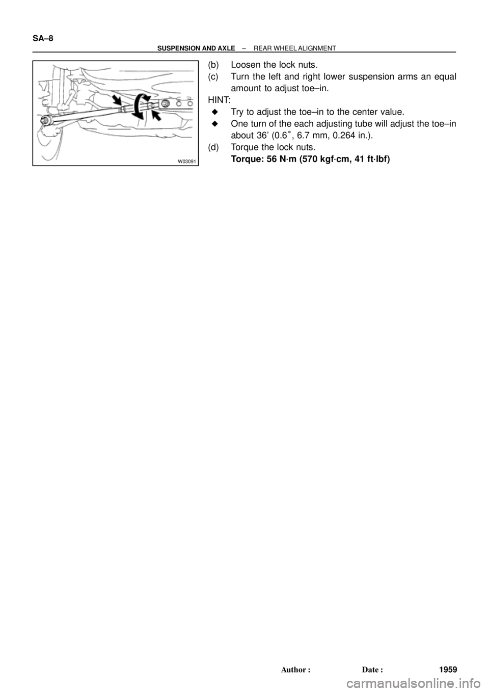
(b) Loosen the lock nuts.
(c) Turn the left and right lower suspension arms an equal
amount to adjust toe±in.
HINT:
�Try to adjust the toe±in to the center value.
�One turn of the each adjusting tube will adjust the toe±in
about 36' (0.6°, 6.7 mm, 0.264 in.).
(d) Torque the lock nuts.
Torque: 56 N´m (570 kgf´cm, 41 ft´lbf)
Page 4349 of 4770
SA07B±01
W03092
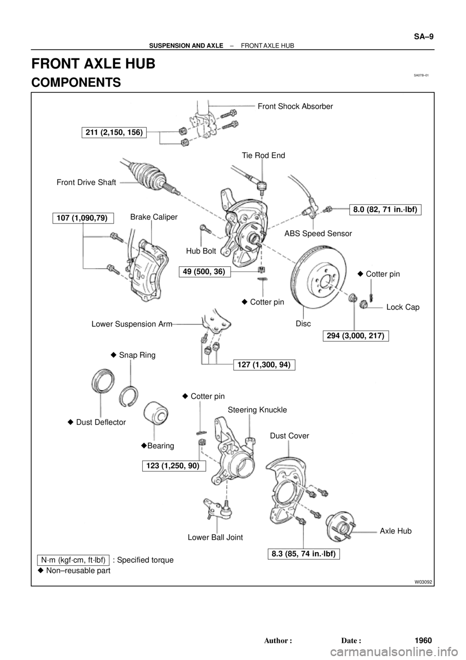
Front Shock Absorber
Tie Rod End
Front Drive Shaft
Brake Caliper
ABS Speed Sensor
Lower Suspension ArmLock Cap
� Snap Ring
� Dust DeflectorSteering Knuckle
Dust Cover
�Bearing
Lower Ball JointAxle Hub
127 (1,300, 94)
294 (3,000, 217)
107 (1,090,79)
8.0 (82, 71 in.´lbf)
123 (1,250, 90)� Cotter pin� Cotter pin� Cotter pin Hub Bolt
Disc
N´m (kgf´cm, ft´lbf) : Specified torque
� Non±reusable part
211 (2,150, 156)
49 (500, 36)
8.3 (85, 74 in.´lbf)
± SUSPENSION AND AXLEFRONT AXLE HUB
SA±9
1960 Author�: Date�:
FRONT AXLE HUB
COMPONENTS
Page 4350 of 4770

2. CHECK BE")
SA07C±01
W03084W03084
W03093
W03139
W03094
SST
SA±10
± SUSPENSION AND AXLEFRONT AXLE HUB
1961 Author�: Date�:
REMOVAL
1. REMOVE FRONT WHEEL
Torque: 103 N´m (1,050 kgf´cm, 76 ft´lbf)
2. CHECK BEARING BACKLASH AND AXLE HUB DEVI-
ATION
(a) Remove the 2 bolts, brake caliper and disc.
(b) Support the brake caliper securely.
(c) Using a dial indicator near the center of the axle hub and
check the backlash in the bearing shaft direction.
Maximum: 0.05 mm (0.0020 in.)
If the backlash exceeds the maximum, replace the bearing.
(d) Using a dial indicator, check the deviation at the surface
of the axle hub outside the hub bolt.
Maximum: 0.05 mm (0.0020 in.)
If the deviation exceeds the maximum, replace the bearing.
(e) Install the disc, 2 bolts and brake caliper.
Torque: 107 N´m (1,090 kgf´cm, 79 ft´lbf)
3. REMOVE DRIVE SHAFT LOCK NUT
(a) Remove the cotter pin and lock cap.
(b) With applying the brakes, remove the nut.
Torque: 294 N´m (3,000 kgf´cm, 217 ft´lbf)
(c) Remove the brake caliper and disc.
4. w/ ABS:
REMOVE ABS SPEED SENSOR AND WIRE HARNESS
CLAMP
Torque: 8.0 N´m (82 kgf´cm, 71 in.´lbf)
5. LOOSEN 2 NUTS ON LOWER SIDE OF SHOCK AB-
SORBER
Torque: 211 N´m (2,150 kgf´cm, 156 ft´lbf)
HINT:
�Do not remove the bolts.
�At the time of installation, coat the nut's thread with en-
gine oil.
6. DISCONNECT TIE ROD END FROM STEERING
KNUCKLE
(a) Remove the cotter pin and nut.
Torque: 49 N´m (500 kgf´cm, 36 ft´lbf)
(b) Using SST, disconnect the tie rod end from the steering
knuckle.
SST 09610±20012
Page 4351 of 4770
W03095
± SUSPENSION AND AXLEFRONT AXLE HUB
SA±11
1962 Author�: Date�:
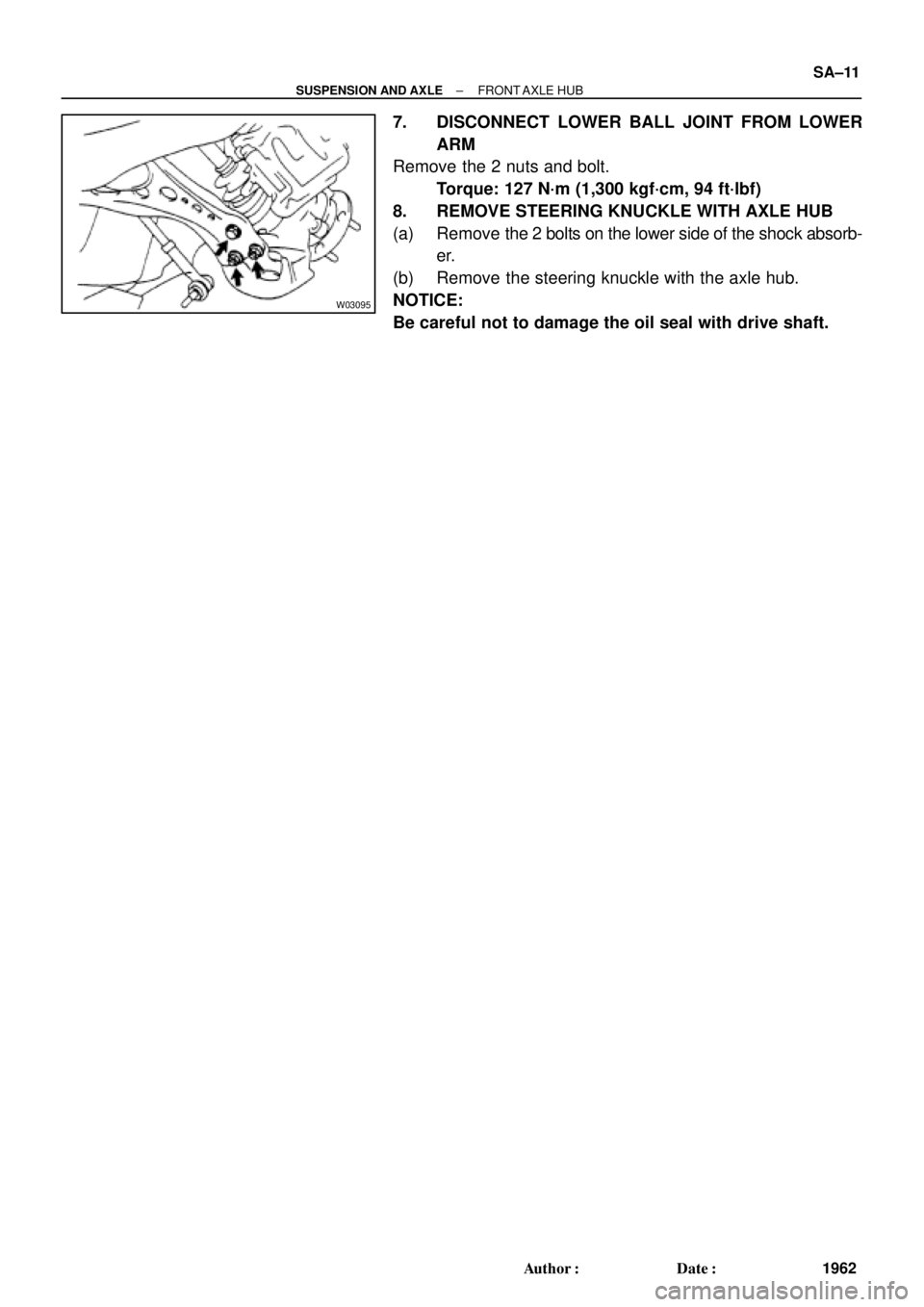
7. DISCONNECT LOWER BALL JOINT FROM LOWER
ARM
Remove the 2 nuts and bolt.
Torque: 127 N´m (1,300 kgf´cm, 94 ft´lbf)
8. REMOVE STEERING KNUCKLE WITH AXLE HUB
(a) Remove the 2 bolts on the lower side of the shock absorb-
er.
(b) Remove the steering knuckle with the axle hub.
NOTICE:
Be careful not to damage the oil seal with drive shaft.
Page 4352 of 4770
SA07D±01
R08859
SST
R00789
SST
W02110
SST
R11486
SST
SST
SA±12
± SUSPENSION AND AXLEFRONT AXLE HUB
1963 Author�: Date�:
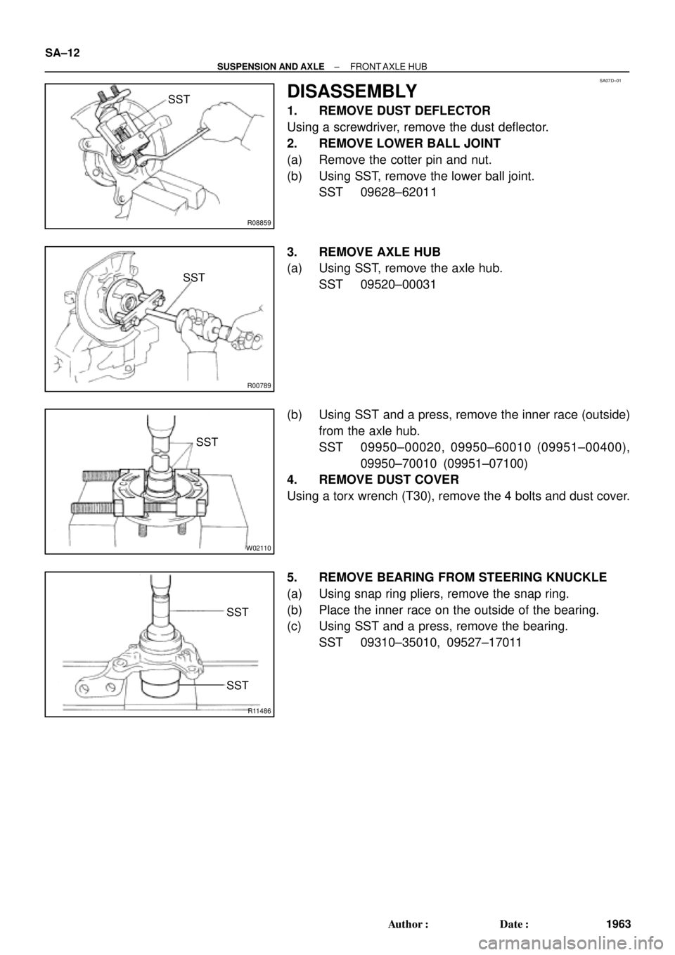
DISASSEMBLY
1. REMOVE DUST DEFLECTOR
Using a screwdriver, remove the dust deflector.
2. REMOVE LOWER BALL JOINT
(a) Remove the cotter pin and nut.
(b) Using SST, remove the lower ball joint.
SST 09628±62011
3. REMOVE AXLE HUB
(a) Using SST, remove the axle hub.
SST 09520±00031
(b) Using SST and a press, remove the inner race (outside)
from the axle hub.
SST 09950±00020, 09950±60010 (09951±00400),
09950±70010 (09951±07100)
4. REMOVE DUST COVER
Using a torx wrench (T30), remove the 4 bolts and dust cover.
5. REMOVE BEARING FROM STEERING KNUCKLE
(a) Using snap ring pliers, remove the snap ring.
(b) Place the inner race on the outside of the bearing.
(c) Using SST and a press, remove the bearing.
SST 09310±35010, 09527±17011
Page 4353 of 4770
SA07E±01
R00792
SST
R08860
SST
SST
Z19236
SST
SST
± SUSPENSION AND AXLEFRONT AXLE HUB
SA±13
1964 Author�: Date�:
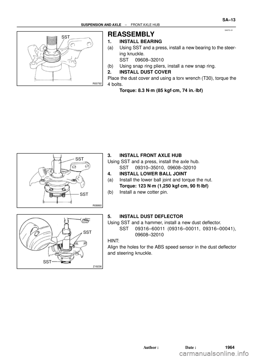
REASSEMBLY
1. INSTALL BEARING
(a) Using SST and a press, install a new bearing to the steer-
ing knuckle.
SST 09608±32010
(b) Using snap ring pliers, install a new snap ring.
2. INSTALL DUST COVER
Place the dust cover and using a torx wrench (T30), torque the
4 bolts.
Torque: 8.3 N´m (85 kgf´cm, 74 in.´lbf)
3. INSTALL FRONT AXLE HUB
Using SST and a press, install the axle hub.
SST 09310±35010, 09608±32010
4. INSTALL LOWER BALL JOINT
(a) Install the lower ball joint and torque the nut.
Torque: 123 N´m (1,250 kgf´cm, 90 ft´lbf)
(b) Install a new cotter pin.
5. INSTALL DUST DEFLECTOR
Using SST and a hammer, install a new dust deflector.
SST 09316±60011 (09316±00011, 09316±00041),
09608±32010
HINT:
Align the holes for the ABS speed sensor in the dust deflector
and steering knuckle.
Page 4354 of 4770
SA07F±01
SA±14
± SUSPENSION AND AXLEFRONT AXLE HUB
1965 Author�: Date�:
INSTALLATION
Installation is in the reverse order of removal (See page SA±10).
AFTER INSTALLATION, CHECK ABS SPEED SENSOR SIGNAL (See page DI±493 or DI±539) AND
FRONT WHEEL ALIGNMENT (See page SA±4)