Page 608 of 698
ENGINE FUEL 6C-1
6F1
6F2
6G
6C
6K
7A
7A1
7B1
7C1
7D
7E
7F
8A
8B
8C
8D
8E
9
10
10A
10B
SECTION 6C
ENGINE FUEL
CONTENTS
GENERAL DESCRIPTION .............................. 6C-1
ON-VEHICLE SERVICE .................................. 6C-2
COMPONENTS ........................................... 6C-2
PRECAUTIONS ........................................... 6C-3
FUEL LINES ................................................. 6C-4
FUEL PIPE ................................................... 6C-4
FUEL FILLER CAP ...................................... 6C-5FUEL TANK INLET VALVE ......................... 6C-6
FUEL TANK ................................................. 6C-7
FUEL PUMP ASSEMBLY .......................... 6C-10
DISASSEMBLY AND REASSEMBLY .... 6C-12
SPECIAL TOOL ............................................ 6C-14
TIGHTENING TORQUE SPECIFICATION.... 6C-14
GENERAL DESCRIPTION
The main components of the fuel system are fuel tank, fuel pump assembly (with fuel filter, fuel level gauge, fuel
pressure regulator and tank pressure control valve), fuel/vapor separator fuel feed line and fuel vapor line.
For the details of fuel flow and fuel vapor flow, refer to “GENERAL DESCRIPTION” in Section 6E. WARNING:
For vehicles equipped with Supplemental Restraint (Air Bag) System:
Service on and around the air bag system components or wiring must be performed only by an
authorized SUZUKI dealer. Refer to “Air Bag System Components and Wiring Location View” under
“General Description” in air bag system section in order to confirm whether you are performing ser-
vice on or near the air bag system components or wiring. Please observe all WARNINGS and “Ser-
vice Precautions” under “On-Vehicle Service” in air bag system section before performing service
on or around the air bag system components or wiring. Failure to follow WARNINGS could result in
unintentional activation of the system or could render the system inoperative. Either of these two
conditions may result in severe injury.
Technical service work must be started at least 90 seconds after the ignition switch is turned to the
“LOCK” position and the negative cable is disconnected from the battery. Otherwise, the system
may be activated by reserve energy in the Sensing and Diagnostic Module (SDM).
CAUTION:
The engine of this vehicle requires the use of unleaded fuel only. Use of leaded and/or low lead fuel
can result in engine damage and reduce the effectiveness of the emission control system.
Page 610 of 698

ENGINE FUEL 6C-3
PRECAUTIONS
WARNING:
Before attempting service of any type on fuel system, the
followings should be always observed in order to reduce
the risk or fire and personal injury.
Disconnect negative cable at battery.
Do not smoke, and place no smoking signs near work
area.
Be sure to have CO
2 fire extinguisher handy.
Be sure to perform work in a well-ventilated area and
away from any open flames (such as gas hot heater).
Wear safety glasses.
To relieve fuel vapor pressure in fuel tank, remove fuel
filler cap from fuel filler neck and then reinstall it.
As fuel feed line is still under high fuel pressure even
after engine was stopped, loosening or disconnecting
fuel feed line directly may cause dangerous spout of
fuel to occur where loosened or disconnected.
Before loosening or disconnecting fuel feed line, make
sure to relieve fuel pressure “FUEL PRESSURE
RELIEF PROCEDURE” in Section 6.
A small amount of fuel may be released after the fuel
line is disconnected. In order to reduce the chance of
personal injury, cover the fitting to be disconnected
with a shop cloth. Be sure to put that cloth in an
approved container when disconnection is completed.
Note that fuel hose connection varies with each type of
pipe. Be sure to connect and clamp each hose cor-
rectly referring to the figure.
[A] : With short pipe, fit hose as far as it reaches pipe joint as shown.
[B] : With the following type pipe, fit hose as far as its peripheral projection as shown.
[C] : With bent pipe, fit hose as far as its bent part as shown or till depth “b”.
[D] : With straight pipe, fit hose till depth “b”.
[E] : With red marked pipe, fit hose end reaches red mark on pipe.
1. Pipe
2. Hose
3. Clamp
4. Ped mark
“a” : Clamp securely at a position 3 to 7 mm (0.12 – 0.27 in.) from hose end.
“b” : 20 to 30 mm (0.79 – 1.18 in.)
“c” : 0 to 5 mm (0 – 0.19 in.)
Page 611 of 698
6C-4 ENGINE FUEL
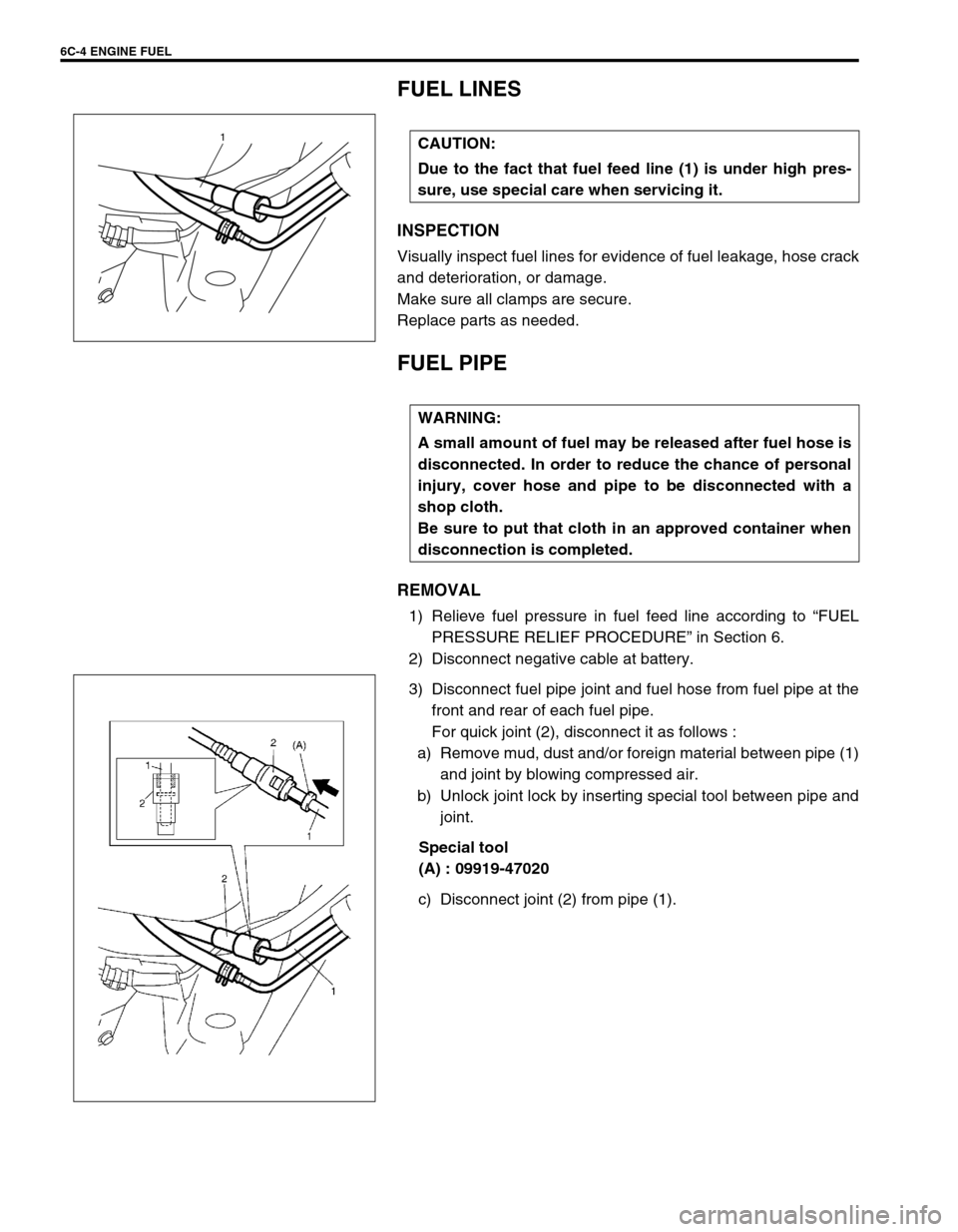
FUEL LINES
INSPECTION
Visually inspect fuel lines for evidence of fuel leakage, hose crack
and deterioration, or damage.
Make sure all clamps are secure.
Replace parts as needed.
FUEL PIPE
REMOVAL
1) Relieve fuel pressure in fuel feed line according to “FUEL
PRESSURE RELIEF PROCEDURE” in Section 6.
2) Disconnect negative cable at battery.
3) Disconnect fuel pipe joint and fuel hose from fuel pipe at the
front and rear of each fuel pipe.
For quick joint (2), disconnect it as follows :
a) Remove mud, dust and/or foreign material between pipe (1)
and joint by blowing compressed air.
b) Unlock joint lock by inserting special tool between pipe and
joint.
Special tool
(A) : 09919-47020
c) Disconnect joint (2) from pipe (1). CAUTION:
Due to the fact that fuel feed line (1) is under high pres-
sure, use special care when servicing it.
1
WARNING:
A small amount of fuel may be released after fuel hose is
disconnected. In order to reduce the chance of personal
injury, cover hose and pipe to be disconnected with a
shop cloth.
Be sure to put that cloth in an approved container when
disconnection is completed.
Page 613 of 698
6C-6 ENGINE FUEL
FUEL TANK INLET VALVE
REMOVAL
1) Remove fuel filler cap.
2) Insert hose of a hand operated pump into fuel filler hose (1)
and drain fuel in space “A” in the figure.
3) Hoist vehicle and remove clamp (2) and fuel filler hose (1)
from fuel tank.
4) Remove fuel tank inlet valve (1) using flat-bladed screw-
driver.
INSPECTION
Check fuel tank inlet valve for the followings.
Damage
Smooth opening and closing
If any damage or malfunction is found, replace.WARNING:
Refer to the WARNING at the beginning of ON-VEHICLE
SERVICE in this section.
CAUTION:
Do not force pump hose into fuel tank, or pump hose
may damage fuel tank inlet valve (2).
1
2
CAUTION:
Be careful not to damage fuel tank inlet valve (1) with flat-
bladed screwdriver.
Page 614 of 698
ENGINE FUEL 6C-7
INSTALLATION
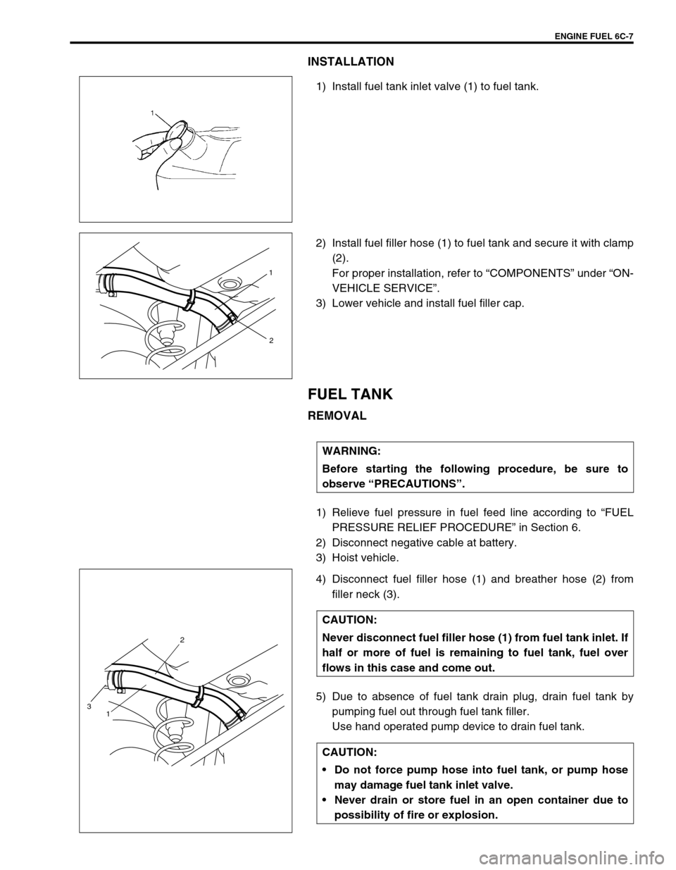
1) Install fuel tank inlet valve (1) to fuel tank.
2) Install fuel filler hose (1) to fuel tank and secure it with clamp
(2).
For proper installation, refer to “COMPONENTS” under “ON-
VEHICLE SERVICE”.
3) Lower vehicle and install fuel filler cap.
FUEL TANK
REMOVAL
1) Relieve fuel pressure in fuel feed line according to “FUEL
PRESSURE RELIEF PROCEDURE” in Section 6.
2) Disconnect negative cable at battery.
3) Hoist vehicle.
4) Disconnect fuel filler hose (1) and breather hose (2) from
filler neck (3).
5) Due to absence of fuel tank drain plug, drain fuel tank by
pumping fuel out through fuel tank filler.
Use hand operated pump device to drain fuel tank.
1
2
WARNING:
Before starting the following procedure, be sure to
observe “PRECAUTIONS”.
CAUTION:
Never disconnect fuel filler hose (1) from fuel tank inlet. If
half or more of fuel is remaining to fuel tank, fuel over
flows in this case and come out.
CAUTION:
Do not force pump hose into fuel tank, or pump hose
may damage fuel tank inlet valve.
Never drain or store fuel in an open container due to
possibility of fire or explosion.
2
1
3
Page 615 of 698
6C-8 ENGINE FUEL
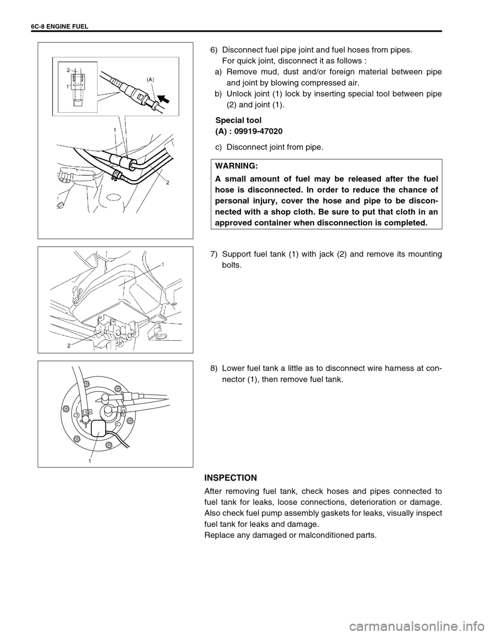
6) Disconnect fuel pipe joint and fuel hoses from pipes.
For quick joint, disconnect it as follows :
a) Remove mud, dust and/or foreign material between pipe
and joint by blowing compressed air.
b) Unlock joint (1) lock by inserting special tool between pipe
(2) and joint (1).
Special tool
(A) : 09919-47020
c) Disconnect joint from pipe.
7) Support fuel tank (1) with jack (2) and remove its mounting
bolts.
8) Lower fuel tank a little as to disconnect wire harness at con-
nector (1), then remove fuel tank.
INSPECTION
After removing fuel tank, check hoses and pipes connected to
fuel tank for leaks, loose connections, deterioration or damage.
Also check fuel pump assembly gaskets for leaks, visually inspect
fuel tank for leaks and damage.
Replace any damaged or malconditioned parts.WARNING:
A small amount of fuel may be released after the fuel
hose is disconnected. In order to reduce the chance of
personal injury, cover the hose and pipe to be discon-
nected with a shop cloth. Be sure to put that cloth in an
approved container when disconnection is completed.
1
Page 616 of 698
ENGINE FUEL 6C-9
FUEL TANK PURGING PROCEDURE
The following procedure is used for purging fuel tank.
1) After removing fuel tank, remove all hoses, pipes, fuel pump
assembly from fuel tank.
2) Drain all remaining fuel from tank.
3) Move tank to flushing area.
4) Fill tank with warm water or tap water, and agitate vigorously
and drain. Repeat this washing until inside of tank is clean.
Replace tank if its inside is rusty.
5) Completely flush out remaining water after washing.
INSTALLATION
1) If parts have been removed from fuel tank, install them
before installing fuel tank to vehicle.
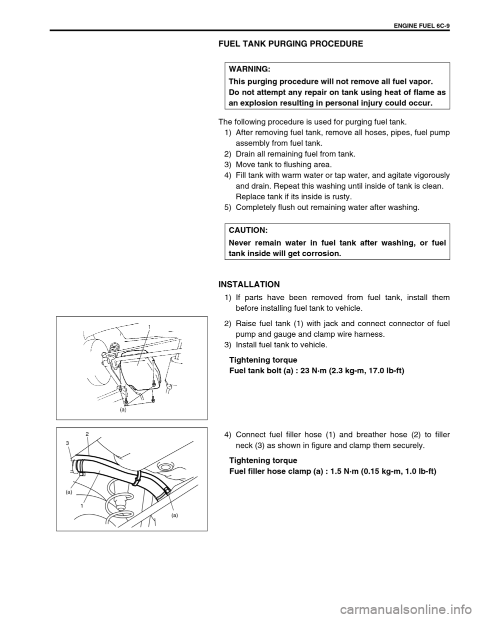
2) Raise fuel tank (1) with jack and connect connector of fuel
pump and gauge and clamp wire harness.
3) Install fuel tank to vehicle.
Tightening torque
Fuel tank bolt (a) : 23 N·m (2.3 kg-m, 17.0 lb-ft)
4) Connect fuel filler hose (1) and breather hose (2) to filler
neck (3) as shown in figure and clamp them securely.
Tightening torque
Fuel filler hose clamp (a) : 1.5 N·m (0.15 kg-m, 1.0 lb-ft) WARNING:
This purging procedure will not remove all fuel vapor.
Do not attempt any repair on tank using heat of flame as
an explosion resulting in personal injury could occur.
CAUTION:
Never remain water in fuel tank after washing, or fuel
tank inside will get corrosion.
(a) (a)
1 32
Page 617 of 698
6C-10 ENGINE FUEL
5) Connect fuel feed hose (1) and vapor hose (2) to each pipe
as shown in figure and clamp them securely.
6) Connect negative cable at battery.
With engine OFF, turn ignition switch to ON position and
check for fuel leaks.
FUEL PUMP ASSEMBLY
REMOVAL
1) Remove fuel tank from vehicle. Refer to “FUEL TANK”.
2) Disconnect fuel breather hose (1), fuel vapor hose (2) and
pipes from fuel pump assembly.
When disconnecting joint of fuel feed line (3) from pipe,
unlock joint by inserting special tool between pipe and joint
lock first.
Special tool
(A) : 09919-47020 CAUTION:
When connecting joint, clean outside surfaces of pipe
where joint is to be inserted, push joint into pipe till
joint lock clicks and check to ensure that pipes are
connected securely, or fuel leak may occur.
Never let the fuel hoses touch the ABS sensor harness
(if equipped).
WARNING:
Refer to the PRECAUTIONS at the beginning of ON-VEHI-
CLE SERVICE.
1
23