2000 SUZUKI SWIFT radiator fan
[x] Cancel search: radiator fanPage 9 of 698

0A-6 GENERAL INFORMATION
Air bag wire harness can be identified easily as it is covered with a yellow protection tube. Be very
careful when handling it.
When an open in air bag wire harness, damaged wire harness, connector or terminal is found,
replace wire harness, connectors and terminals as an assembly.
Do not apply power to the air bag system unless all components are connected or a diagnostic chart
requests it, as this will set a diagnostic trouble code.
Never use air bag system component parts from another vehicle.
When using electric welding, be sure to temporarily disable air bag system referring to “DISABLING
AIR BAG SYSTEM” in Section 10B.
Never expose air bag system component parts directly to hot air (drying or baking the vehicle after
painting) or flames.
WARNING/CAUTION labels are attached on each part of air bag system components. Be sure to fol-
low the instructions.
After vehicle is completely repaired, perform “AIR BAG DIAGNOSTIC SYSTEM CHECK” in SECTION
10B.
GENERAL PRECAUTIONS
The WARNING and CAUTION below describe some general precautions that you should observe when servic-
ing a vehicle. These general precautions apply to many of the service procedures described in this manual, and
they will not necessarily be repeated with each procedure to which they apply.
WARNING:
Whenever raising a vehicle for service, be sure to follow the instructions under “VEHICLE LIFTING
POINTS” in this section.
When it is necessary to do service work with the engine running, make sure that the parking brake
is set fully and the transmission is in Neutral (for manual transmission vehicles) or Park (for auto-
matic transmission vehicles), Keep hands, hair, clothing, tools, etc. away from the fan and belts
when the engine is running.
When it is necessary to run the engine indoors, make sure that the exhaust gas is forced outdoors.
Do not perform service work in areas where combustible materials can come in contact with a hot
exhaust system. When working with toxic or flammable materials (such as gasoline and refriger-
ant), make sure that the area you work in is well-ventilated.
To avoid getting burned, keep away from hot metal parts such as the radiator, exhaust manifold, tail
pipe, muffler, etc.
New and used engine oil can be hazardous. Children and pets may be harmed by swallowing new or
used oil. Keep new and used oil and used engine oil filters away from children and pets.
Continuous contact with used engine oil has been found to cause [skin] cancer in laboratory ani-
mals. Brief contact with used oil may irritate skin. To minimize your exposure to used engine oil,
wear a long-sleeve shirt and moisture-proof gloves (such as dish washing gloves) when changing
engine oil. If engine oil contacts your skin, wash thoroughly with soap and water. Launder any
clothing or rags if wet with oil, recycle or properly dispose of used oil and filters.
Make sure the bonnet is fully closed and latched before driving. If it is not, it can fly up unexpect-
edly during driving, obstructing your view and resulting in an accident.
Page 22 of 698

GENERAL INFORMATION 0A-19
WARNING, CAUTION AND INFORMATION LABELS
The figure below shows main labels among others that are attached to vehicle component parts.
When servicing and handling parts, refer to WARNING/CAUTION instructions printed on labels.
If any WARNING/CAUTION label is found stained or damaged, clean or replace it as necessary.
1. Air bag label on back side of engine hood (if equipped)
2. Air bag label on sun visor (if equipped)
3. Radiator cap label
4. Engine cooling fan label
1. Air bag label on driver air bag (inflator) module 4. Air bag label on SDM
2. Air bag label on combination switch and contact coil assembly 5. Pretensioner label on seat belt retractor
3. Air bag label on passenger air bag (inflator) module [A] : These labels are attached on vehicle equipped with air bag system only.
5
Page 67 of 698

1B-2 AIR CONDITIONING (OPTIONAL)
REMOVING MANIFOLD GAUGE SET ...... 1B-26
LEAK TEST................................................ 1B-26
LIQUID LEAK DETECTORS .................. 1B-26
ON-VEHICLE SERVICE ................................ 1B-27
SERVICE PRECAUTION........................... 1B-27
REFRIGERANT LINE ............................ 1B-27
HANDLING REFRIGERANT HFC-134a
(R-134a) ................................................. 1B-28
REFRIGERANT RECOVERY ................ 1B-28
REFRIGERANT CHARGE ..................... 1B-28
CONDENSER ASSEMBLY........................ 1B-28
RECEIVER/DRYER ................................... 1B-30
RADIATOR/CONDENSER COOLING FAN
MOTOR...................................................... 1B-31COOLING UNIT (EVAPORATOR) ............ 1B-32
A/C EVAPORATOR TEMPERATURE
SENSOR.................................................... 1B-34
EXPANSION VALVE ................................. 1B-34
A/C REFRIGERANT PRESSURE
SWITCH..................................................... 1B-35
A/C SWITCH.............................................. 1B-36
RADIATOR/CONDENSER COOLING FAN
MOTOR RELAY No.1, No.2 and No.3 ....... 1B-36
COMPRESSOR ......................................... 1B-36
MAGNET CLUTCH .................................... 1B-38
LIP TYPE SEAL ......................................... 1B-41
REQUIRED SERVICE MATERIAL ............... 1B-43
SPECIAL TOOL ............................................ 1B-44
Page 70 of 698

AIR CONDITIONING (OPTIONAL) 1B-5
DIAGNOSIS
GENERAL DIAGNOSIS TABLE
Condition Possible Cause Correction
Cool air won’t come
out (A/C system won’t
operative)No refrigerant Perform recover, evacuation and charging.
Fuse blown Check fuses in circuit fuse and main fuse
boxes, and check short circuit to ground.
A/C switch faulty Check A/C switch.
Blower fan switch faulty Check blower fan switch referring to Sec-
tion 1A.
A/C evaporator temperature sensor
faultyCheck A/C evaporator temperature sen-
sor.
A/C refrigerant pressure switch faulty Check A/C refrigerant pressure switch.
Wiring or grounding faulty Repair as necessary.
ECT sensor faulty Check ECT sensor referring to Section
6E1.
ECM and its circuit faulty Check ECM and its circuit referring to Sec-
tion 6E1.
Cool air won’t come
out (A/C compressor
won’t operative)ECM faulty Check ECM and its circuit referring to Sec-
tion 6E1.
Magnet clutch faulty Check magnet clutch.
Compressor drive belt loosen or broken Adjust or replace drive belt.
Compressor faulty Check compressor.
Compressor thermal switch faulty Check compressor thermal switch
Cool air won’t come
out (A/C condenser
cooling fan motor
won’t operative)Fuse blown Check fuses in circuit fuse and main fuse
boxes, and check short circuit to ground.
Wiring or grounding faulty Repair as necessary.
Radiator/condenser cooling fan motor
relay faultyCheck radiator/condenser cooling fan
motor relay No.1, No.2 and No.3.
Radiator/condenser cooling fan motor
faultyCheck radiator/condenser cooling fan
motor.
ECM faulty Check ECM and its circuit referring to Sec-
tion 6E1.
Cool air won’t come
out (Blower fan motor
won’t operative)Fuse blown Check “HTR” fuse in circuit fuse box and
main fuses, and check short circuit to
ground.
Blower fan motor resistor faulty Check blower fan motor resistor to Section
1A.
Blower fan switch faulty Check blower fan switch referring to Sec-
tion 1A.
Wiring or grounding faulty Repair as necessary.
Blower fan motor faulty Check blower fan motor referring to Sec-
tion 1A.
Page 75 of 698

1B-10 AIR CONDITIONING (OPTIONAL)
PERFORMANCE DIAGNOSIS
1) Confirm that vehicle and environmental conditions are as fol-
lows.
Vehicle is not exposed to direct sun.
Ambient temperature is within 15 – 35°C (59 – 95°F).
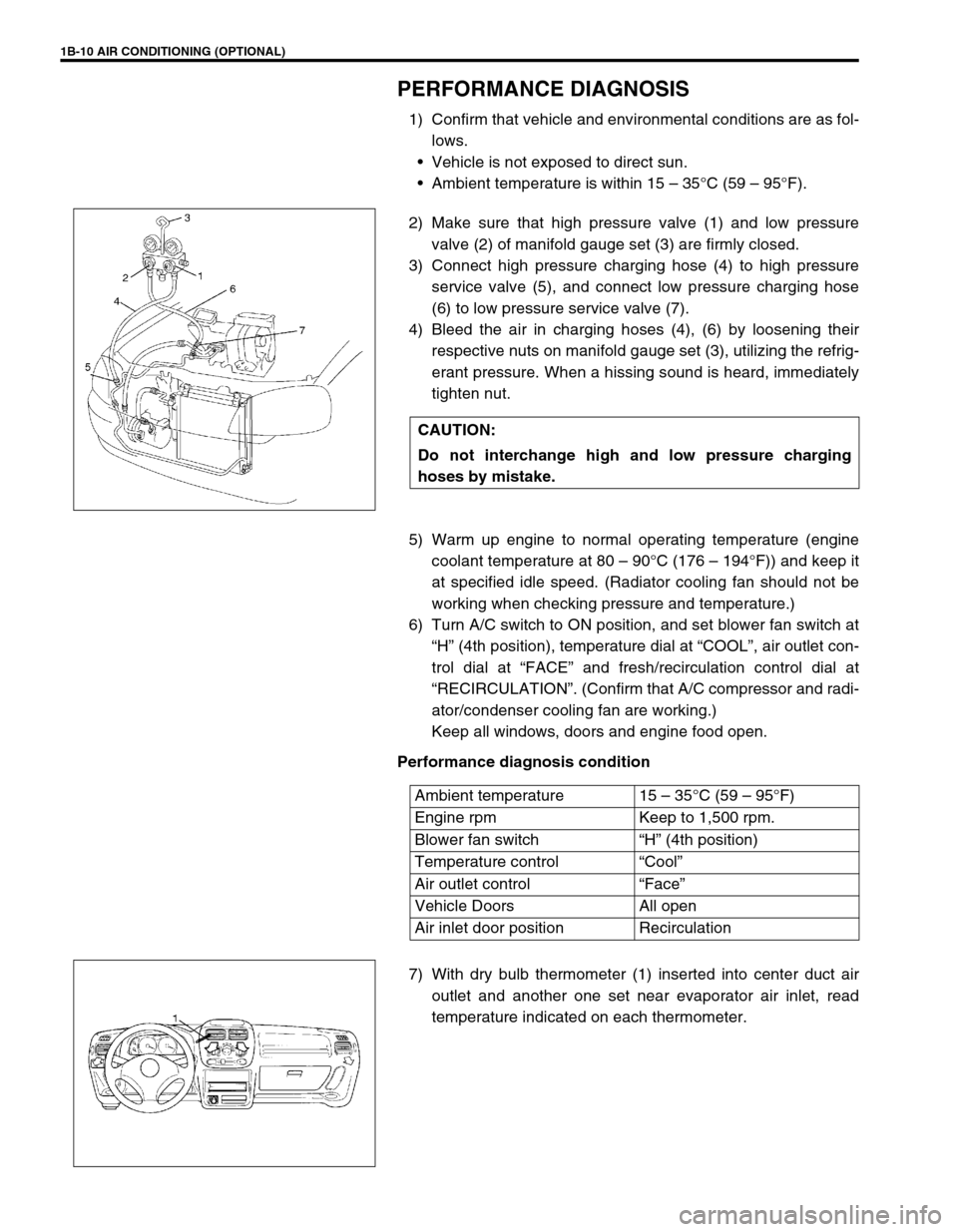
2) Make sure that high pressure valve (1) and low pressure
valve (2) of manifold gauge set (3) are firmly closed.
3) Connect high pressure charging hose (4) to high pressure
service valve (5), and connect low pressure charging hose
(6) to low pressure service valve (7).
4) Bleed the air in charging hoses (4), (6) by loosening their
respective nuts on manifold gauge set (3), utilizing the refrig-
erant pressure. When a hissing sound is heard, immediately
tighten nut.
5) Warm up engine to normal operating temperature (engine
coolant temperature at 80 – 90°C (176 – 194°F)) and keep it
at specified idle speed. (Radiator cooling fan should not be
working when checking pressure and temperature.)
6) Turn A/C switch to ON position, and set blower fan switch at
“H” (4th position), temperature dial at “COOL”, air outlet con-
trol dial at “FACE” and fresh/recirculation control dial at
“RECIRCULATION”. (Confirm that A/C compressor and radi-
ator/condenser cooling fan are working.)
Keep all windows, doors and engine food open.
Performance diagnosis condition
7) With dry bulb thermometer (1) inserted into center duct air
outlet and another one set near evaporator air inlet, read
temperature indicated on each thermometer. CAUTION:
Do not interchange high and low pressure charging
hoses by mistake.
Ambient temperature 15 – 35°C (59 – 95°F)
Engine rpm Keep to 1,500 rpm.
Blower fan switch“H” (4th position)
Temperature control“Cool”
Air outlet control“Face”
Vehicle Doors All open
Air inlet door position Recirculation
Page 77 of 698

1B-12 AIR CONDITIONING (OPTIONAL)
PERFORMANCE DIAGNOSIS TABLE
HIGH PRESSURE GAUGE
LOW PRESSURE GAUGE
THERMOMETER AT CENTER DUCT
NOTE:
If ambient temperature is approximately 30°C (86°F), it is possible to diagnose A/C system in detail
referring to “DETAIL DIAGNOSIS TABLE (AMBIENT TEMPERATURE AT 30 °C (86°F))” under “PER-
FORMANCE DIAGNOSIS” in this section.
Condition Possible Cause Correction
Pressure high
(“A” area of high side
graph)Refrigerant overcharged Recharge.
Expansion valve frozen or clogged Check expansion valve.
Clogged refrigerant passage of high side Clean or replace.
Radiator/condenser cooling fan malfunction (Insufficient
cooling of condenser)Check radiator/condenser cooling fan.
Dirty or bent condenser fins (Insufficient cooling of con-
denser)Clean or repair.
Compressor malfunction (Insufficient oil etc.) Check compressor.
Engine overheat Check engine cooling system referring to
Section 6B.
Pressure low
(“B” area of high side
graph)Insufficient refrigerant (Insufficient charge or leakage) Check for leakage, repair if necessary
and recharge.
Expansion valve malfunction (valve opens too wide) Check expansion valve.
Compressor malfunction (Insufficient compression) Check compressor.
Condition Possible Cause Correction
Pressure high
(“C” area of low side
graph)Expansion valve malfunction (valve opens too wide) Check expansion valve.
Compressor malfunction (Insufficient compression) Check compressor.
Pressure low
(“D” area of low side
graph)Insufficient refrigerant (Insufficient charge or leakage) Check for leakage, repair if necessary
and recharge.
Expansion valve malfunction (valve opens too narrow) Check expansion valve.
Clogged refrigerant passage (crashed pipe) Repair or replace.
Condition Possible Cause Correction
Outlet air temperature at
center duct is high
(Crossing point is in area
“E”)Insufficient or excessive charge of refrigerant Check refrigerant pressure.
Dirty or bent A/C evaporator fins Clean or repair.
Air leakage from cooling (heater) unit or air duct Repair or replace.
Malfunctioning, switch over function of door in cooling
(heater) unitRepair or replace.
Compressor malfunction Check compressor.
Outlet air temperature at
center duct is low
(Crossing point is in area
“F”)Insufficient air volume from center duct (Heater blower
malfunction)Check blower motor and fan.
Compressor malfunction Check compressor.
Page 79 of 698

1B-14 AIR CONDITIONING (OPTIONAL)
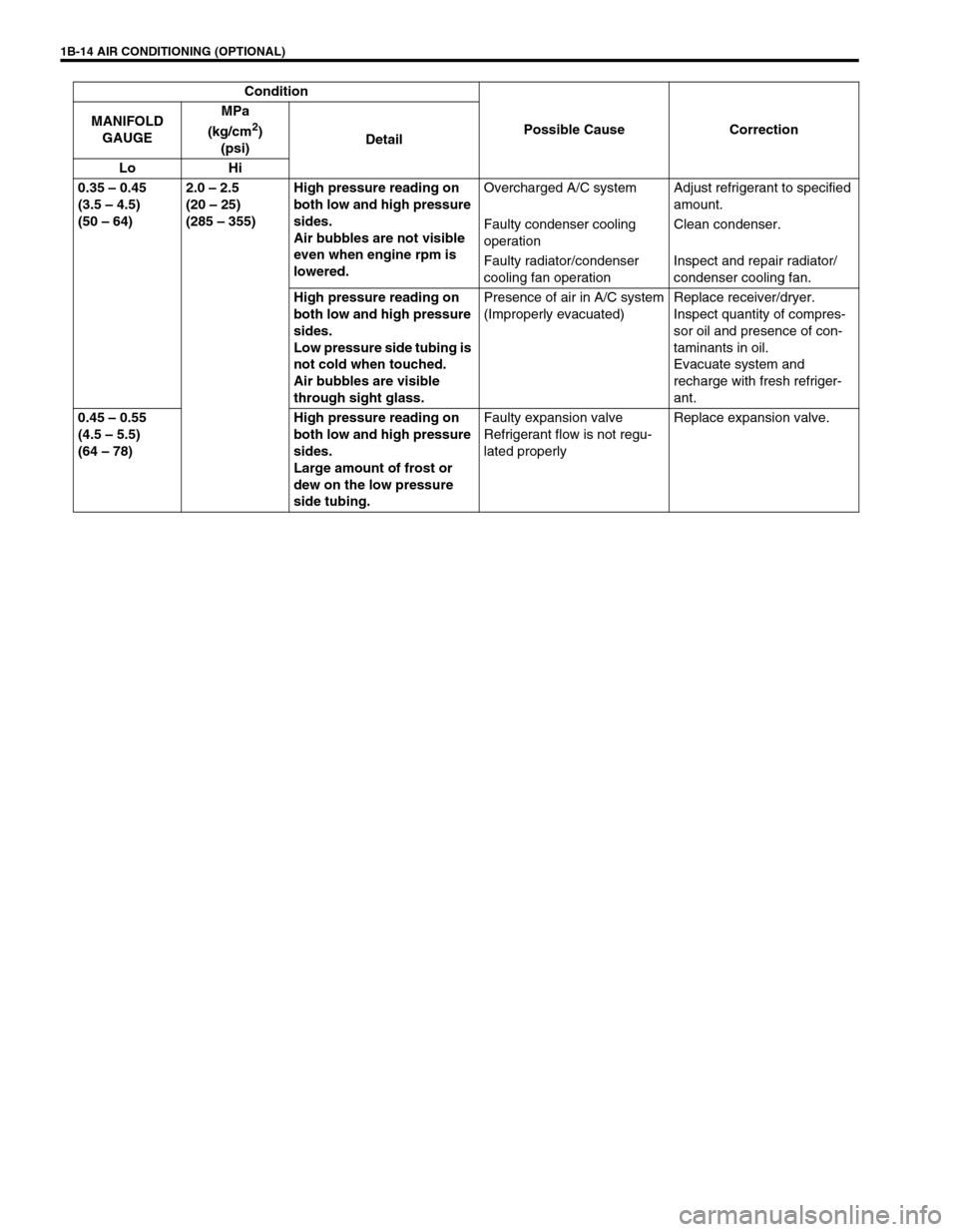
0.35 – 0.45
(3.5 – 4.5)
(50 – 64)2.0 – 2.5
(20 – 25)
(285 – 355)High pressure reading on
both low and high pressure
sides.
Air bubbles are not visible
even when engine rpm is
lowered.Overcharged A/C system Adjust refrigerant to specified
amount.
Faulty condenser cooling
operationClean condenser.
Faulty radiator/condenser
cooling fan operationInspect and repair radiator/
condenser cooling fan.
High pressure reading on
both low and high pressure
sides.
Low pressure side tubing is
not cold when touched.
Air bubbles are visible
through sight glass.Presence of air in A/C system
(Improperly evacuated)Replace receiver/dryer.
Inspect quantity of compres-
sor oil and presence of con-
taminants in oil.
Evacuate system and
recharge with fresh refriger-
ant.
0.45 – 0.55
(4.5 – 5.5)
(64 – 78)High pressure reading on
both low and high pressure
sides.
Large amount of frost or
dew on the low pressure
side tubing.Faulty expansion valve
Refrigerant flow is not regu-
lated properlyReplace expansion valve. Condition
Possible Cause Correction MANIFOLD
GAUGEMPa
(kg/cm
2)
(psi)Detail
Lo Hi
Page 81 of 698

1B-16 AIR CONDITIONING (OPTIONAL)
ELECTRICAL DIAGNOSIS
WIRING DIAGRAM
1. Blower fan motor 6. Radiator/condenser cooling fan relay No.2 11. Ignition switch 16. Main fuse box
2. Blower fan motor resistor 7. Radiator/condenser cooling fan relay No.3 12. A/C evaporator temperature sensor 17. Generator
3. Blower fan switch and A/C switch 8. Radiator/condenser cooling fan motor 13. ECT sensor 18. Compressor
4. A/C refrigerant pressure switch 9. Compressor thermal switch 14. Lighting switch
5. Radiator/condenser cooling fan relay No.1 10. Main relay 15. Circuit fuse box