Page 593 of 698
6B-4 ENGINE COOLING
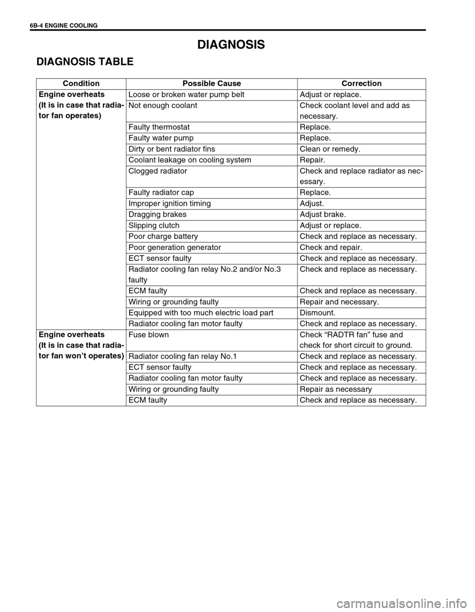
DIAGNOSIS
DIAGNOSIS TABLE
Condition Possible Cause Correction
Engine overheats
(It is in case that radia-
tor fan operates)Loose or broken water pump belt Adjust or replace.
Not enough coolant Check coolant level and add as
necessary.
Faulty thermostat Replace.
Faulty water pump Replace.
Dirty or bent radiator fins Clean or remedy.
Coolant leakage on cooling system Repair.
Clogged radiator Check and replace radiator as nec-
essary.
Faulty radiator cap Replace.
Improper ignition timing Adjust.
Dragging brakes Adjust brake.
Slipping clutch Adjust or replace.
Poor charge battery Check and replace as necessary.
Poor generation generator Check and repair.
ECT sensor faulty Check and replace as necessary.
Radiator cooling fan relay No.2 and/or No.3
faultyCheck and replace as necessary.
ECM faulty Check and replace as necessary.
Wiring or grounding faulty Repair and necessary.
Equipped with too much electric load part Dismount.
Radiator cooling fan motor faulty Check and replace as necessary.
Engine overheats
(It is in case that radia-
tor fan won’t operates)Fuse blown Check “RADTR fan” fuse and
check for short circuit to ground.
Radiator cooling fan relay No.1 Check and replace as necessary.
ECT sensor faulty Check and replace as necessary.
Radiator cooling fan motor faulty Check and replace as necessary.
Wiring or grounding faulty Repair as necessary
ECM faulty Check and replace as necessary.
Page 594 of 698
ENGINE COOLING 6B-5
SYSTEM CIRCUIT
SYSTEM CIRCUIT INSPECTION
Refer to “RADIATOR COOLINGFAN CONTROL SYSTEM CHECK” in Section 6
1. Main fuse box 6. ECM main fuse 11. Radiator and condenser cooling fan motor
2. Generator 7. ECM main relay 12. Refrigerant pressure triple switch (if equipped with A/C)
3. Battery 8. Radiator and condenser cooling fan relay No.1 13. ECT sensor
4. Battery fuse 9. Radiator and condenser cooling fan relay No.2 14. ECM
5. RADTR fuse 10. Radiator and condenser cooling fan relay No.3 15. TO A/C switch
ACG
15A 30A
BLU/WHT
BLK/YEL
BLK
BLU
ORN
BLK
BLK
BLUH–
H+
L– L+
GRN/BLK
BLU/BLK
BRN/WHT
YEL/GRN
PNK/GRN
PPL/YEL
LT GRN/BLK
BLK/RED
BLK/RED 80A
145
6
2
3
7
8
9
11
10
13 15
12
14
Page 599 of 698
6B-10 ENGINE COOLING
ON-VEHICLE SERVICE
SYSTEM COMPONENTS
WARNING:
Check to make sure that engine coolant temperature is cold before removing any part of cooling
system.
Also be sure to disconnect negative cord from battery terminal before removing any part.
1. Radiator 11. To throttle body 21. To timing chain cover
2. Reservoir tank 12. To heater unit 22. O-Ring
3. Radiator cap 13. To water pump 23. Gasket
4. Drain plug 14. Radiator and condenser cooling fan assembly 24. Water outlet cap O-ring No.1
5. Radiator outlet hose 15. Water inlet pipe No.1 25. Water outlet cap O-ring No.2
6. Radiator inlet hose 16. Water inlet pipe No.2 26. Thermostat cap bolts
7. Thermostat 17. Thermostat cap 27. Thermostat case bolts
8. ECT sensor 18. Water outlet cap Tightening torque
9. Thermostat case 19. Heater inlet hose Do not reuse.
10. To cylinder head 20. Heater outlet hose
Page 603 of 698
6B-14 ENGINE COOLING
RADIATOR
REMOVAL
1) Disconnect negative cable at battery.
2) Drain cooling system by loosening drain plug of radiator.
Refer to “COOLING SYSTEM DRAINING”.
3) Disconnect connector of cooling fan motor.
4) Remove air cleaner inlet hose (1) and suction pipe (2).
5) Remove reservoir tank (1) and then its bracket (2).
6) Disconnect radiator inlet and outlet hoses from radiator.
7) Remove cooling fan assembly (3).
8) Remove radiator.
INSPECTION
Check radiator for leakage or damage. Straighten bent fins, if
any.
CLEANING
Clean frontal area of radiator cores.
INSTALLATION
Reverse removal procedures, noting the followings.
Refill cooling system with proper coolant referring to “COOL-
ING SYSTEM REFILL”.
After installation, check each joint for leakage.
Page 604 of 698
ENGINE COOLING 6B-15
RADIATOR AND CONDENSER COOLING FAN
Refer to “RADIATOR AND CONDENSER COOLING FAN” in
Section 1B for removal, inspection and installation.
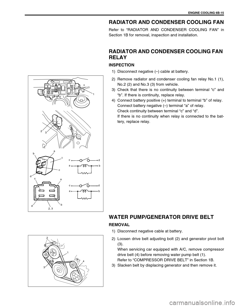
RADIATOR AND CONDENSER COOLING FAN
RELAY
INSPECTION
1) Disconnect negative (–) cable at battery.
2) Remove radiator and condenser cooling fan relay No.1 (1),
No.2 (2) and No.3 (3) from vehicle.
3) Check that there is no continuity between terminal “c” and
“b”. If there is continuity, replace relay.
4) Connect battery positive (+) terminal to terminal “b” of relay.
Connect battery negative (–) terminal “a” of relay.
Check continuity between terminal “c” and “d”.
If there is no continuity when relay is connected to the bat-
tery, replace relay.
WATER PUMP/GENERATOR DRIVE BELT
REMOVAL
1) Disconnect negative cable at battery.
2) Loosen drive belt adjusting bolt (2) and generator pivot bolt
(3).
When servicing car equipped with A/C, remove compressor
drive belt (4) before removing water pump belt (1).
Refer to “COMPRESSOR DRIVE BELT” in Section 1B.
3) Slacken belt by displacing generator and then remove it.
ba
1
c
dc
ad
b
2
3
1
c
d
2, 3b a
ac
d
b
2
3
1
4
Page 623 of 698
6E1-2 ENGINE AND EMISSION CONTROL SYSTEM
CRANKSHAFT POSITION SENSOR .. 6E1-32
VEHICLE SPEED SENSOR (VSS) ...... 6E1-33
FUEL LEVEL SENSOR (GAUGE) ....... 6E1-33
KNOCK SENSOR (IF EQUIPPED) ...... 6E1-33
MAIN RELAY, FUEL PUMP RELAY
AND RADIATOR FAN RELAY NO.1.... 6E1-33
FUEL CUT OPERATION ..................... 6E1-34
RADIATOR FAN CONTROL
SYSTEM .............................................. 6E1-34
RADIATOR FAN RELAY NO. 2 AND
NO.3 ..................................................... 6E1-34OUTPUT SIGNALS OF THROTTLE
VALVE OPENING AND ENGINE
COOLANT TEMP. (VEHICLE WITH
A/T ONLY) ........................................... 6E1-36
EMISSION CONTROL SYSTEM ............. 6E1-36
EGR SYSTEM ..................................... 6E1-36
EVAPORATIVE EMISSION CONTROL
SYSTEM .............................................. 6E1-37
PCV SYSTEM ...................................... 6E1-39
SPECIAL TOOL .......................................... 6E1-40
TIGHTENING TORQUE SPECIFICATION . 6E1-41
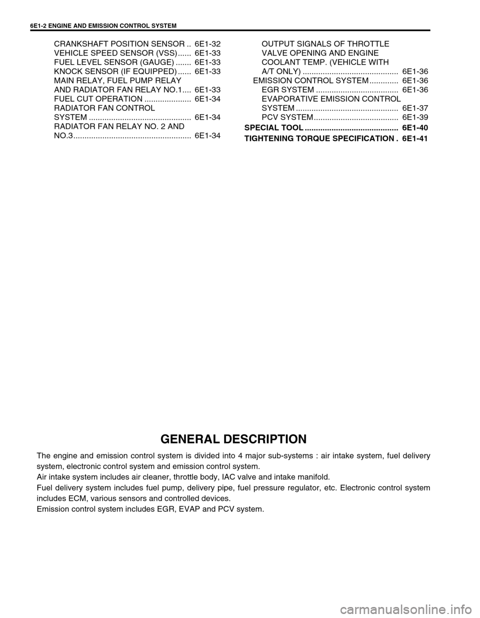
GENERAL DESCRIPTION
The engine and emission control system is divided into 4 major sub-systems : air intake system, fuel delivery
system, electronic control system and emission control system.
Air intake system includes air cleaner, throttle body, IAC valve and intake manifold.
Fuel delivery system includes fuel pump, delivery pipe, fuel pressure regulator, etc. Electronic control system
includes ECM, various sensors and controlled devices.
Emission control system includes EGR, EVAP and PCV system.
Page 628 of 698
ENGINE AND EMISSION CONTROL SYSTEM 6E1-7
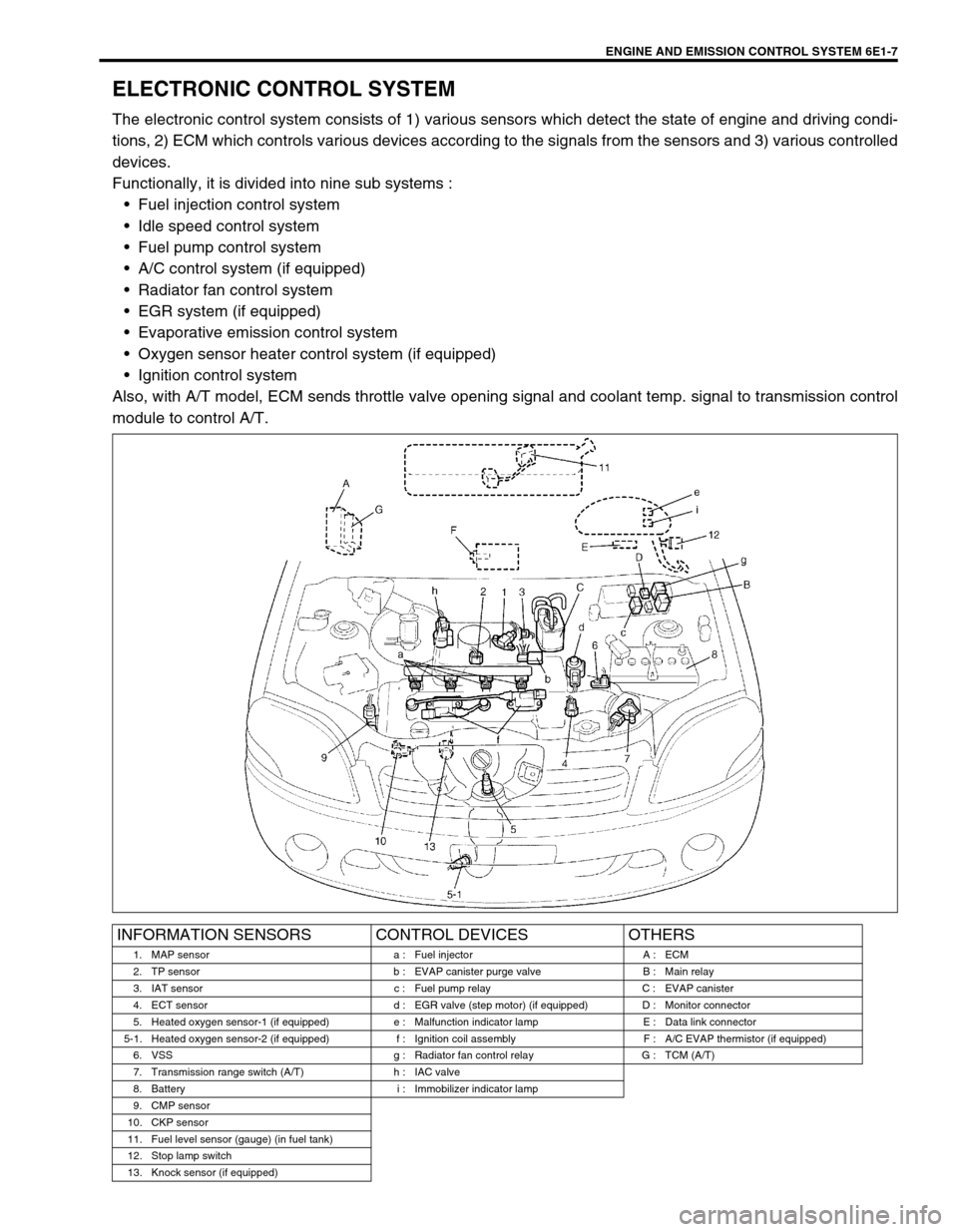
ELECTRONIC CONTROL SYSTEM
The electronic control system consists of 1) various sensors which detect the state of engine and driving condi-
tions, 2) ECM which controls various devices according to the signals from the sensors and 3) various controlled
devices.
Functionally, it is divided into nine sub systems :
Fuel injection control system
Idle speed control system
Fuel pump control system
A/C control system (if equipped)
Radiator fan control system
EGR system (if equipped)
Evaporative emission control system
Oxygen sensor heater control system (if equipped)
Ignition control system
Also, with A/T model, ECM sends throttle valve opening signal and coolant temp. signal to transmission control
module to control A/T.
INFORMATION SENSORS CONTROL DEVICES OTHERS
1. MAP sensor a : Fuel injector A : ECM
2. TP sensor b : EVAP canister purge valve B : Main relay
3. IAT sensor c : Fuel pump relay C : EVAP canister
4. ECT sensor d : EGR valve (step motor) (if equipped) D : Monitor connector
5. Heated oxygen sensor-1 (if equipped) e : Malfunction indicator lamp E : Data link connector
5-1. Heated oxygen sensor-2 (if equipped) f : Ignition coil assembly F : A/C EVAP thermistor (if equipped)
6. VSS g : Radiator fan control relay G : TCM (A/T)
7. Transmission range switch (A/T) h : IAC valve
8. Battery i : Immobilizer indicator lamp
9. CMP sensor
10. CKP sensor
11. Fuel level sensor (gauge) (in fuel tank)
12. Stop lamp switch
13. Knock sensor (if equipped)
Page 629 of 698
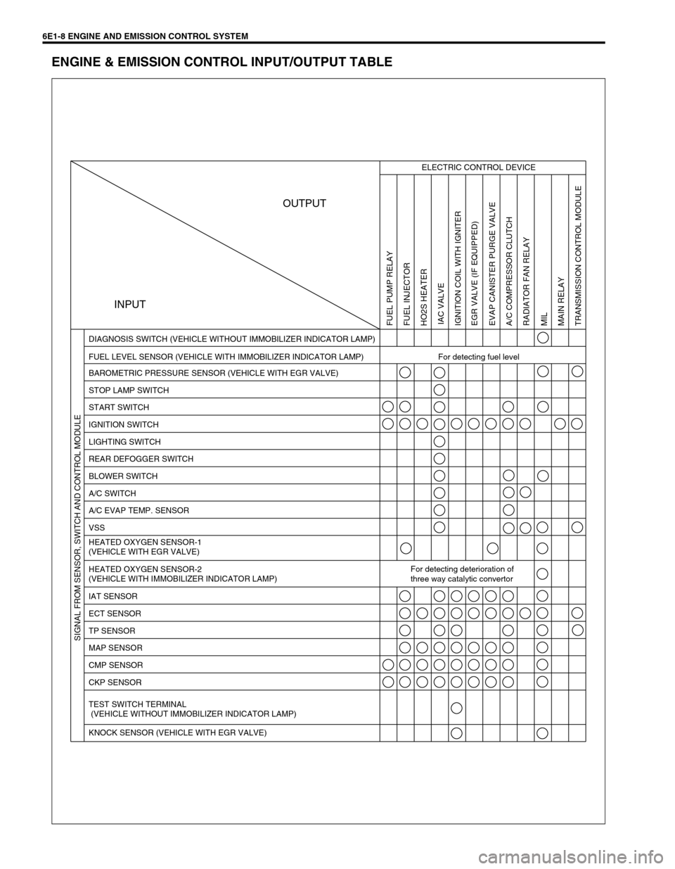
6E1-8 ENGINE AND EMISSION CONTROL SYSTEM
ENGINE & EMISSION CONTROL INPUT/OUTPUT TABLE
INPUTOUTPUT
ELECTRIC CONTROL DEVICE
FUEL LEVEL SENSOR (VEHICLE WITH IMMOBILIZER INDICATOR LAMP) For detecting fuel level DIAGNOSIS SWITCH (VEHICLE WITHOUT IMMOBILIZER INDICATOR LAMP)
BAROMETRIC PRESSURE SENSOR (VEHICLE WITH EGR VALVE)
STOP LAMP SWITCH
START SWITCH
IGNITION SWITCH
LIGHTING SWITCH
REAR DEFOGGER SWITCH
BLOWER SWITCH
A/C SWITCH
A/C EVAP TEMP. SENSOR
VSS
HEATED OXYGEN SENSOR-1
(VEHICLE WITH EGR VALVE)
HEATED OXYGEN SENSOR-2
(VEHICLE WITH IMMOBILIZER INDICATOR LAMP)For detecting deterioration of
three way catalytic convertor
IAT SENSOR
ECT SENSOR
TP SENSOR
MAP SENSOR
CMP SENSOR
CKP SENSOR
TEST SWITCH TERMINAL
(VEHICLE WITHOUT IMMOBILIZER INDICATOR LAMP)
KNOCK SENSOR (VEHICLE WITH EGR VALVE)
FUEL PUMP RELAY
FUEL INJECTOR
HO2S HEATER
IAC VALVE
IGNITION COIL WITH IGNITER
EGR VALVE (IF EQUIPPED)
EVAP CANISTER PURGE VALVE
A/C COMPRESSOR CLUTCH
RADIATOR FAN RELAY
MIL
MAIN RELAY
TRANSMISSION CONTROL MODULE SIGNAL FROM SENSOR, SWITCH AND CONTROL MODULE