Page 22 of 698
GENERAL INFORMATION 0A-19
WARNING, CAUTION AND INFORMATION LABELS
The figure below shows main labels among others that are attached to vehicle component parts.
When servicing and handling parts, refer to WARNING/CAUTION instructions printed on labels.
If any WARNING/CAUTION label is found stained or damaged, clean or replace it as necessary.
1. Air bag label on back side of engine hood (if equipped)
2. Air bag label on sun visor (if equipped)
3. Radiator cap label
4. Engine cooling fan label
1. Air bag label on driver air bag (inflator) module 4. Air bag label on SDM
2. Air bag label on combination switch and contact coil assembly 5. Pretensioner label on seat belt retractor
3. Air bag label on passenger air bag (inflator) module [A] : These labels are attached on vehicle equipped with air bag system only.
5
Page 37 of 698
0B-8 MAINTENANCE AND LUBRICATION
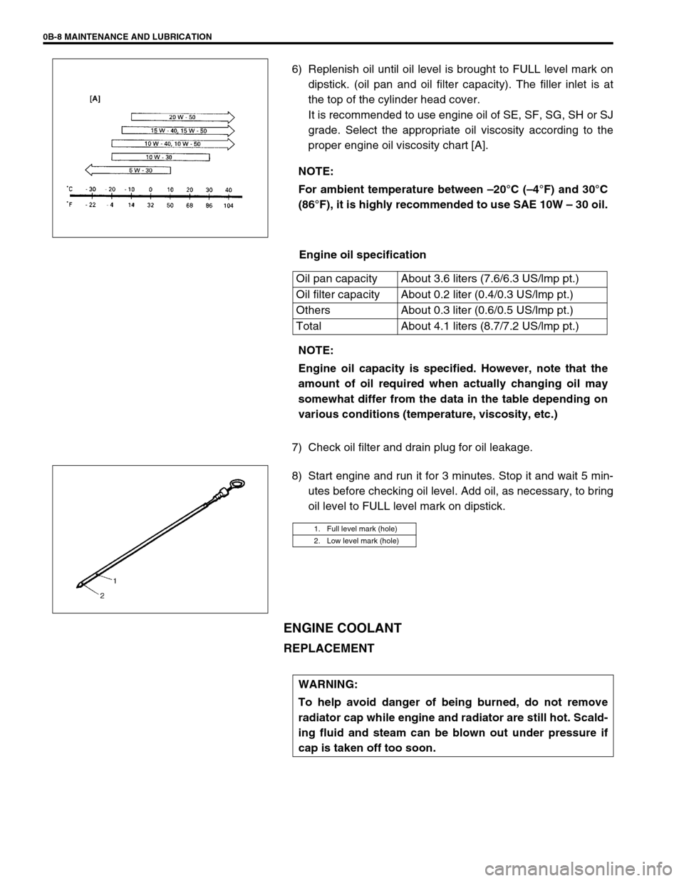
6) Replenish oil until oil level is brought to FULL level mark on
dipstick. (oil pan and oil filter capacity). The filler inlet is at
the top of the cylinder head cover.
It is recommended to use engine oil of SE, SF, SG, SH or SJ
grade. Select the appropriate oil viscosity according to the
proper engine oil viscosity chart [A].
Engine oil specification
7) Check oil filter and drain plug for oil leakage.
8) Start engine and run it for 3 minutes. Stop it and wait 5 min-
utes before checking oil level. Add oil, as necessary, to bring
oil level to FULL level mark on dipstick.
ENGINE COOLANT
REPLACEMENT
NOTE:
For ambient temperature between –20°C (–4°F) and 30°C
(86°F), it is highly recommended to use SAE 10W – 30 oil.
Oil pan capacity About 3.6 liters (7.6/6.3 US/lmp pt.)
Oil filter capacity About 0.2 liter (0.4/0.3 US/lmp pt.)
Others About 0.3 liter (0.6/0.5 US/lmp pt.)
Total About 4.1 liters (8.7/7.2 US/lmp pt.)
NOTE:
Engine oil capacity is specified. However, note that the
amount of oil required when actually changing oil may
somewhat differ from the data in the table depending on
various conditions (temperature, viscosity, etc.)
1. Full level mark (hole)
2. Low level mark (hole)
WARNING:
To help avoid danger of being burned, do not remove
radiator cap while engine and radiator are still hot. Scald-
ing fluid and steam can be blown out under pressure if
cap is taken off too soon.
Page 38 of 698
MAINTENANCE AND LUBRICATION 0B-9
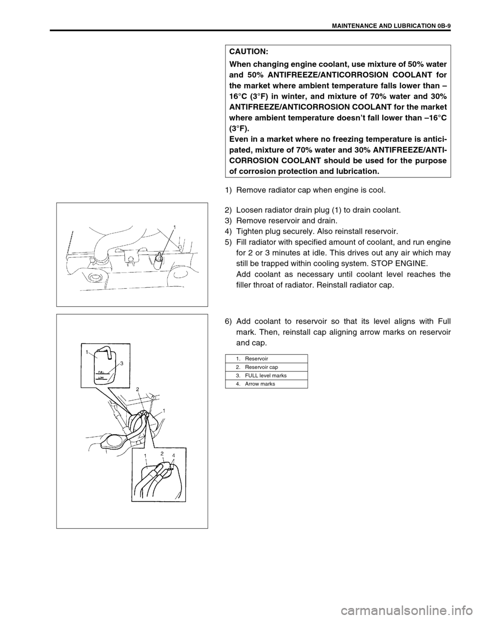
1) Remove radiator cap when engine is cool.
2) Loosen radiator drain plug (1) to drain coolant.
3) Remove reservoir and drain.
4) Tighten plug securely. Also reinstall reservoir.
5) Fill radiator with specified amount of coolant, and run engine
for 2 or 3 minutes at idle. This drives out any air which may
still be trapped within cooling system. STOP ENGINE.
Add coolant as necessary until coolant level reaches the
filler throat of radiator. Reinstall radiator cap.
6) Add coolant to reservoir so that its level aligns with Full
mark. Then, reinstall cap aligning arrow marks on reservoir
and cap. CAUTION:
When changing engine coolant, use mixture of 50% water
and 50% ANTIFREEZE/ANTICORROSION COOLANT for
the market where ambient temperature falls lower than –
16°C (3°F) in winter, and mixture of 70% water and 30%
ANTIFREEZE/ANTICORROSION COOLANT for the market
where ambient temperature doesn’t fall lower than –16°C
(3°F).
Even in a market where no freezing temperature is antici-
pated, mixture of 70% water and 30% ANTIFREEZE/ANTI-
CORROSION COOLANT should be used for the purpose
of corrosion protection and lubrication.
1. Reservoir
2. Reservoir cap
3. FULL level marks
4. Arrow marks
Page 96 of 698
AIR CONDITIONING (OPTIONAL) 1B-31
Tighten receiver/dryer cap to specified torque
Tightening torque
Receiver / dryer cap : 13 N·m (1.3 kg-m, 9.5 lb-ft)
Replenish specified amount of compressor oil to compressor
suction side by referring to “REPLENISHING COMPRES-
SOR OIL” in this section.
RADIATOR/CONDENSER COOLING FAN
MOTOR
REMOVAL AND INSTALLATION
For details, refer to “RADIATOR” in Section 6B.
INSPECTION
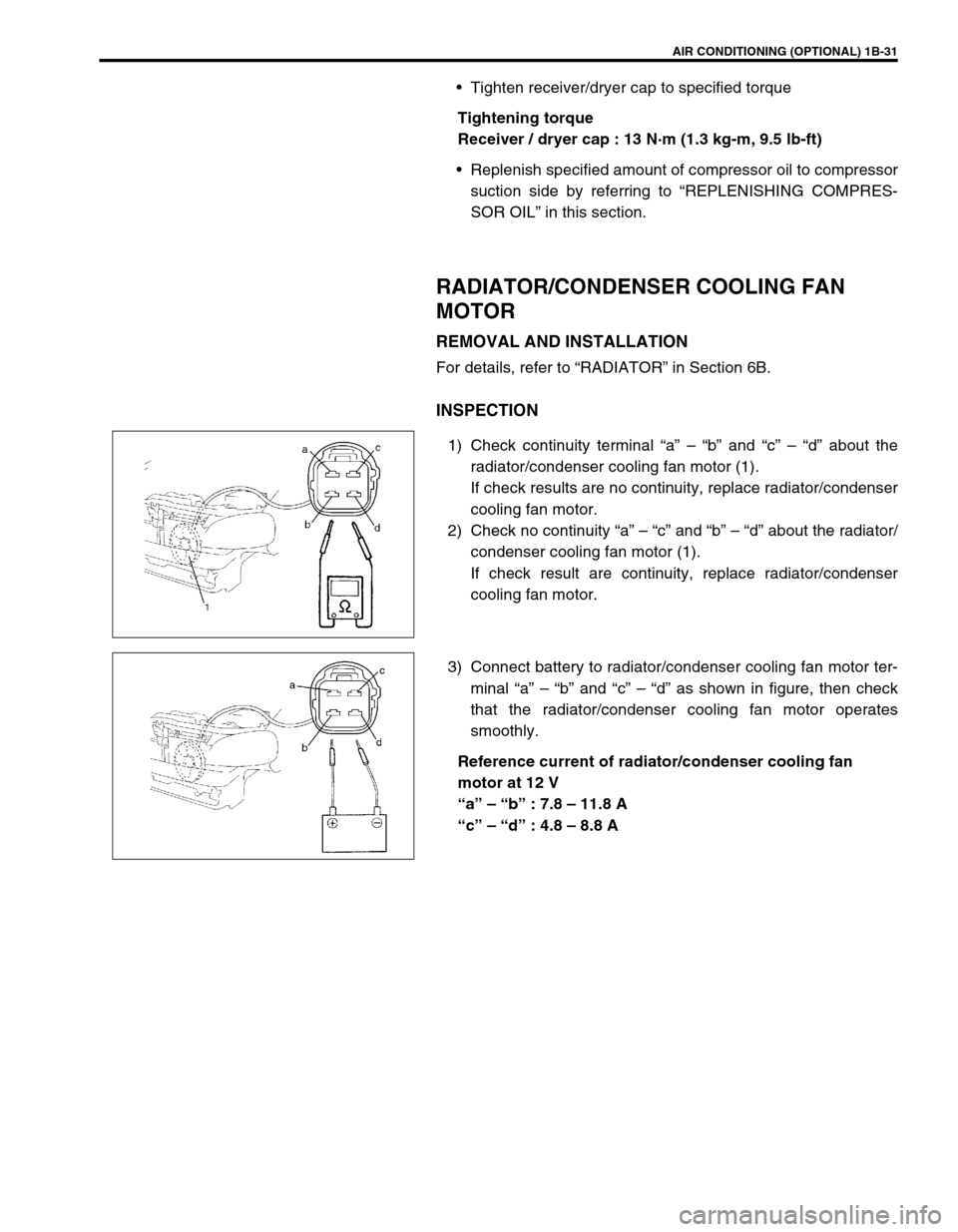
1) Check continuity terminal “a” – “b” and “c” – “d” about the
radiator/condenser cooling fan motor (1).
If check results are no continuity, replace radiator/condenser
cooling fan motor.
2) Check no continuity “a” – “c” and “b” – “d” about the radiator/
condenser cooling fan motor (1).
If check result are continuity, replace radiator/condenser
cooling fan motor.
3) Connect battery to radiator/condenser cooling fan motor ter-
minal “a” – “b” and “c” – “d” as shown in figure, then check
that the radiator/condenser cooling fan motor operates
smoothly.
Reference current of radiator/condenser cooling fan
motor at 12 V
“a” – “b” : 7.8 – 11.8 A
“c” – “d” : 4.8 – 8.8 A
Page 310 of 698
BRAKES 5-37
7) Install cup (1) and washer (2) such a direction as shown.
8) Remove cap cup (1) from cap with caring not to cause any
damage to inside of cap (2).
9) Install cap cup and O-rings (3) to cap such a direction as
shown.
10) Install cap and tighten it to specified torque, then confirm the
length “A”.
Tightening torque
Cap (a) : 14 N·m (1.4 kg-m, 10.5 lb-ft)
Cap installation position
“A” : Less than 26 mm (1.02 in.)
INSPECTION AFTER ASSEMBLY
1) Install radiator cap test with special tool to master cylinder
port (1).
Special tool
(A) : 09952-46010
(B) : 09952-26020
2) Apply air and confirm that pressure is not applied.NOTE:
Primary cup is the same as secondary cup.
Primary cup is the largest compared with that of cap
and sleeve.
NOTE:
For without ABS vehicle, install special tool (B) to oppo-
site side port (2).
1(B)
2 (A)
Page 311 of 698
5-38 BRAKES
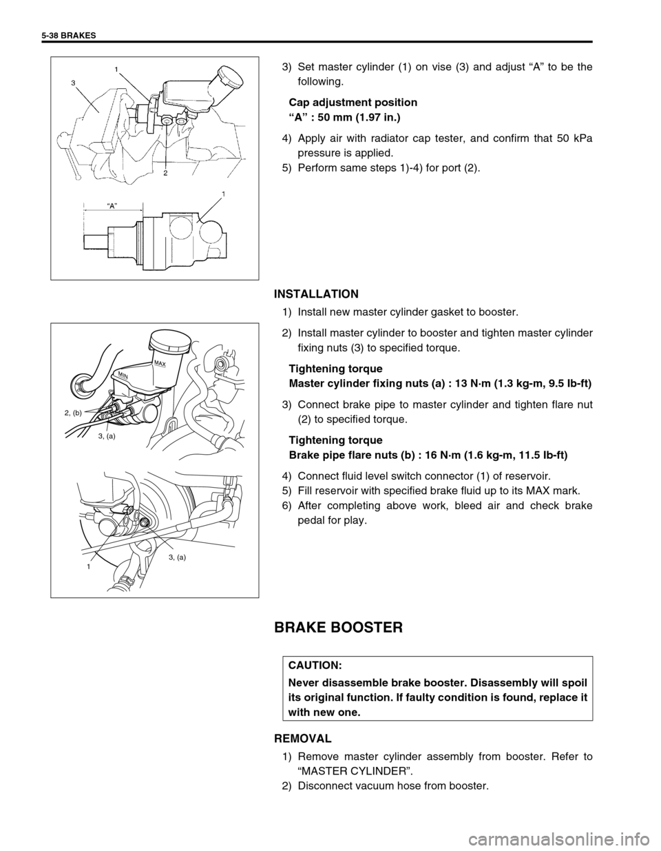
3) Set master cylinder (1) on vise (3) and adjust “A” to be the
following.
Cap adjustment position
“A” : 50 mm (1.97 in.)
4) Apply air with radiator cap tester, and confirm that 50 kPa
pressure is applied.
5) Perform same steps 1)-4) for port (2).
INSTALLATION
1) Install new master cylinder gasket to booster.
2) Install master cylinder to booster and tighten master cylinder
fixing nuts (3) to specified torque.
Tightening torque
Master cylinder fixing nuts (a) : 13 N·m (1.3 kg-m, 9.5 Ib-ft)
3) Connect brake pipe to master cylinder and tighten flare nut
(2) to specified torque.
Tightening torque
Brake pipe flare nuts (b) : 16 N·m (1.6 kg-m, 11.5 Ib-ft)
4) Connect fluid level switch connector (1) of reservoir.
5) Fill reservoir with specified brake fluid up to its MAX mark.
6) After completing above work, bleed air and check brake
pedal for play.
BRAKE BOOSTER
REMOVAL
1) Remove master cylinder assembly from booster. Refer to
“MASTER CYLINDER”.
2) Disconnect vacuum hose from booster.
3, (a)
1
3, (a) 2, (b)
CAUTION:
Never disassemble brake booster. Disassembly will spoil
its original function. If faulty condition is found, replace it
with new one.
Page 396 of 698
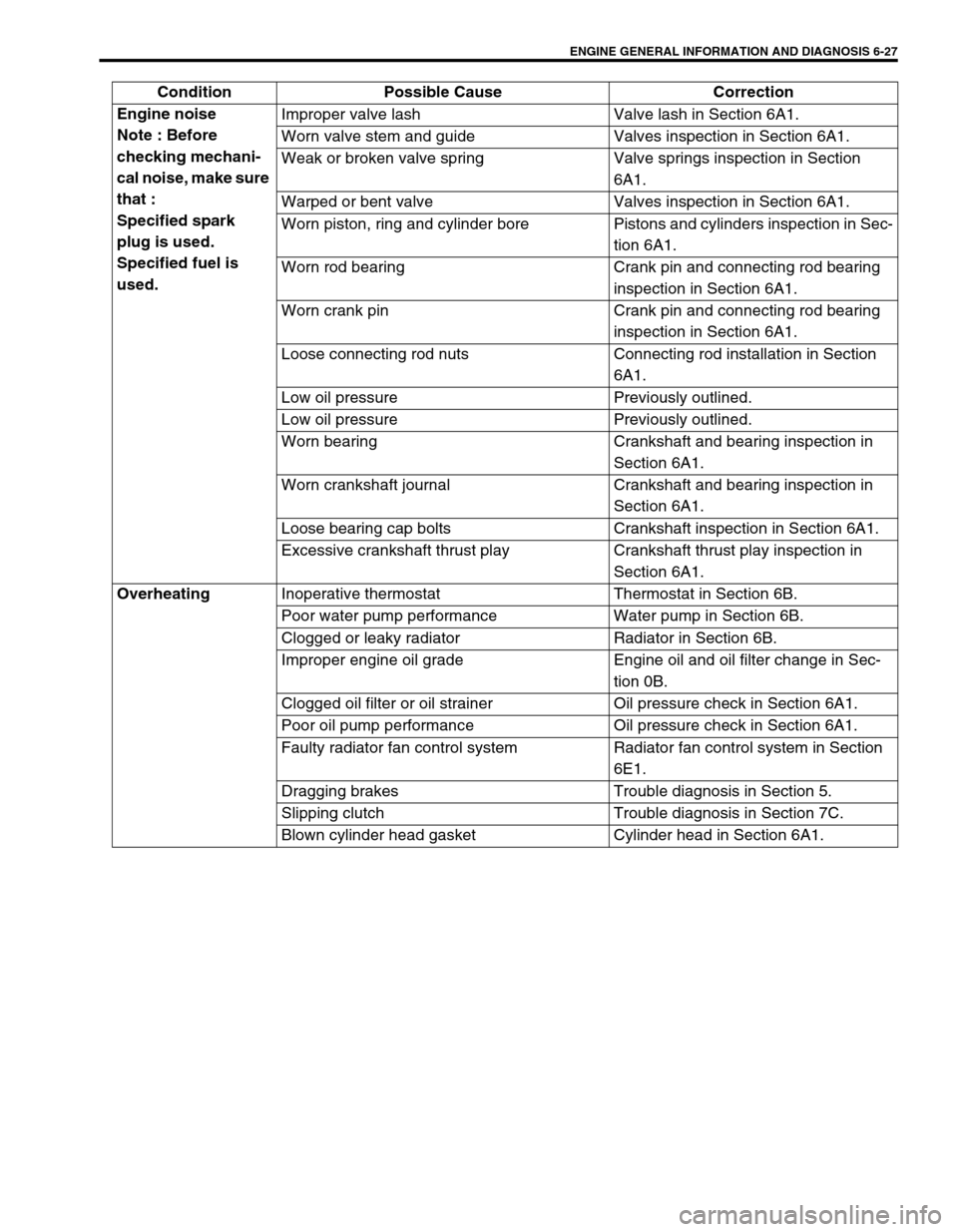
ENGINE GENERAL INFORMATION AND DIAGNOSIS 6-27
Engine noise
Note : Before
checking mechani-
cal noise, make sure
that :
Specified spark
plug is used.
Specified fuel is
used.Improper valve lash Valve lash in Section 6A1.
Worn valve stem and guide Valves inspection in Section 6A1.
Weak or broken valve spring Valve springs inspection in Section
6A1.
Warped or bent valve Valves inspection in Section 6A1.
Worn piston, ring and cylinder bore Pistons and cylinders inspection in Sec-
tion 6A1.
Worn rod bearing Crank pin and connecting rod bearing
inspection in Section 6A1.
Worn crank pin Crank pin and connecting rod bearing
inspection in Section 6A1.
Loose connecting rod nuts Connecting rod installation in Section
6A1.
Low oil pressure Previously outlined.
Low oil pressure Previously outlined.
Worn bearing Crankshaft and bearing inspection in
Section 6A1.
Worn crankshaft journal Crankshaft and bearing inspection in
Section 6A1.
Loose bearing cap bolts Crankshaft inspection in Section 6A1.
Excessive crankshaft thrust play Crankshaft thrust play inspection in
Section 6A1.
Overheating
Inoperative thermostat Thermostat in Section 6B.
Poor water pump performance Water pump in Section 6B.
Clogged or leaky radiator Radiator in Section 6B.
Improper engine oil grade Engine oil and oil filter change in Sec-
tion 0B.
Clogged oil filter or oil strainer Oil pressure check in Section 6A1.
Poor oil pump performance Oil pressure check in Section 6A1.
Faulty radiator fan control system Radiator fan control system in Section
6E1.
Dragging brakes Trouble diagnosis in Section 5.
Slipping clutch Trouble diagnosis in Section 7C.
Blown cylinder head gasket Cylinder head in Section 6A1. Condition Possible Cause Correction
Page 404 of 698
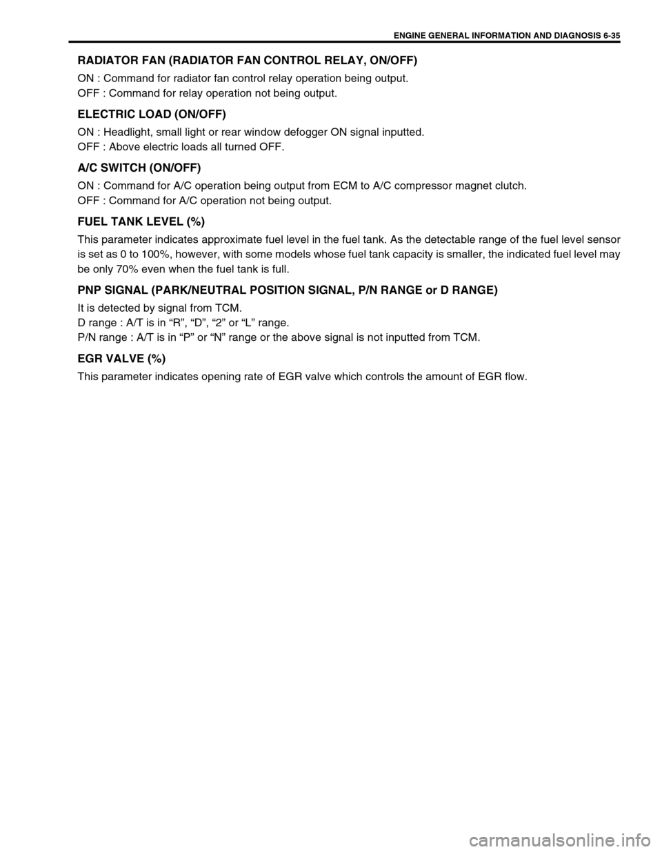
ENGINE GENERAL INFORMATION AND DIAGNOSIS 6-35
RADIATOR FAN (RADIATOR FAN CONTROL RELAY, ON/OFF)
ON : Command for radiator fan control relay operation being output.
OFF : Command for relay operation not being output.
ELECTRIC LOAD (ON/OFF)
ON : Headlight, small light or rear window defogger ON signal inputted.
OFF : Above electric loads all turned OFF.
A/C SWITCH (ON/OFF)
ON : Command for A/C operation being output from ECM to A/C compressor magnet clutch.
OFF : Command for A/C operation not being output.
FUEL TANK LEVEL (%)
This parameter indicates approximate fuel level in the fuel tank. As the detectable range of the fuel level sensor
is set as 0 to 100%, however, with some models whose fuel tank capacity is smaller, the indicated fuel level may
be only 70% even when the fuel tank is full.
PNP SIGNAL (PARK/NEUTRAL POSITION SIGNAL, P/N RANGE or D RANGE)
It is detected by signal from TCM.
D range : A/T is in “R”, “D”, “2” or “L” range.
P/N range : A/T is in “P” or “N” range or the above signal is not inputted from TCM.
EGR VALVE (%)
This parameter indicates opening rate of EGR valve which controls the amount of EGR flow.