2000 SUZUKI SWIFT oil level
[x] Cancel search: oil levelPage 32 of 698

MAINTENANCE AND LUBRICATION 0B-3
IntervalKm (x 1,000) 153045607590
Miles (x 1,000) 9 18 27 36 45 54
Months 12 24 36 48 60 72
BRAKE
Brake discs and pads (thickness, wear, damage) I I I I I I
Brake drums and shoes (wear, damage)–I–I–I
Brake hoses and pipes (leakage, damage, clamp)–I–I–I
Brake fluid–R–R–R
Brake lever and cable (damage, stroke, operation) Inspect at first 15,000 km (9,000 miles only)
CHASSIS AND BODY
Clutch (pedal height and travel)–I–I–I
Tires (wear, damage, rotation) /wheels (damage) I I I I I I
Suspension system (tightness, damage, rattle, breakage)–I–I–I
Steering system (tightness, damage, breakage, rattle)–I–I–I
Drive shaft (axle) boots/Propeller shafts (4WD)––I––I
Manual transmission oil (leakage, level) (I : 1st 15,000 km only) I–R––R
Automatic transmission
fluidFluid level–I–I–I
Fluid change Replace every 165,000 km (99,000 miles)
Transfer oil (4WD) (leakage, level) I–I–I–
Rear differential oil (4WD) (leakage, level) (R : 1st 15,000 km
only)R or I–I–I–
All latches, hinges and locks–I–I–I
NOTE:
“R” : Replace or change
“I” : Inspect and correct or replace if necessary
Page 37 of 698
0B-8 MAINTENANCE AND LUBRICATION
6) Replenish oil until oil level is brought to FULL level mark on
dipstick. (oil pan and oil filter capacity). The filler inlet is at
the top of the cylinder head cover.
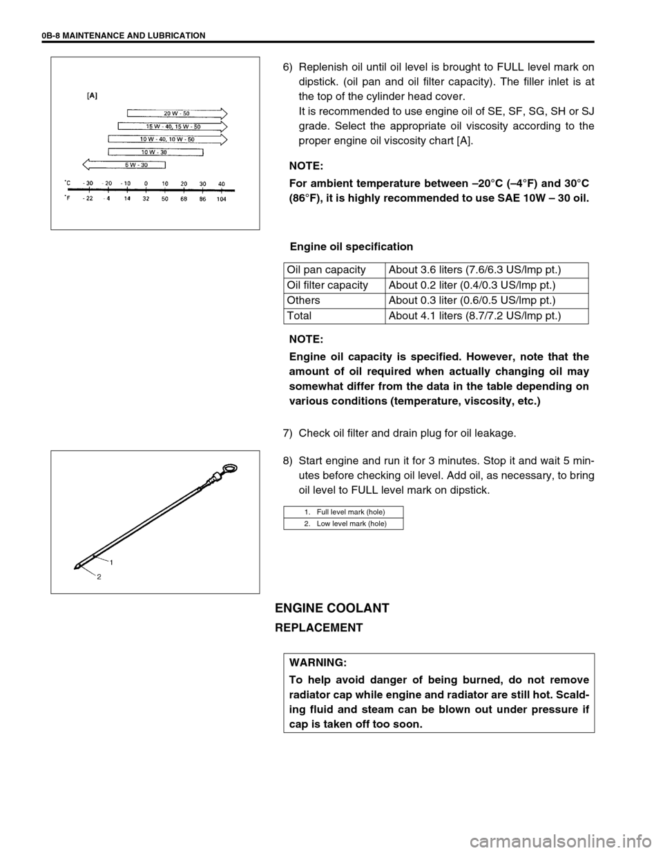
It is recommended to use engine oil of SE, SF, SG, SH or SJ
grade. Select the appropriate oil viscosity according to the
proper engine oil viscosity chart [A].
Engine oil specification
7) Check oil filter and drain plug for oil leakage.
8) Start engine and run it for 3 minutes. Stop it and wait 5 min-
utes before checking oil level. Add oil, as necessary, to bring
oil level to FULL level mark on dipstick.
ENGINE COOLANT
REPLACEMENT
NOTE:
For ambient temperature between –20°C (–4°F) and 30°C
(86°F), it is highly recommended to use SAE 10W – 30 oil.
Oil pan capacity About 3.6 liters (7.6/6.3 US/lmp pt.)
Oil filter capacity About 0.2 liter (0.4/0.3 US/lmp pt.)
Others About 0.3 liter (0.6/0.5 US/lmp pt.)
Total About 4.1 liters (8.7/7.2 US/lmp pt.)
NOTE:
Engine oil capacity is specified. However, note that the
amount of oil required when actually changing oil may
somewhat differ from the data in the table depending on
various conditions (temperature, viscosity, etc.)
1. Full level mark (hole)
2. Low level mark (hole)
WARNING:
To help avoid danger of being burned, do not remove
radiator cap while engine and radiator are still hot. Scald-
ing fluid and steam can be blown out under pressure if
cap is taken off too soon.
Page 46 of 698
MAINTENANCE AND LUBRICATION 0B-17
MANUAL TRANSMISSION OIL
INSPECTION
1) Inspect transmission case for evidence of oil leakage.
Repair leaky point if any.
2) Make sure that vehicle is placed level for oil level check.
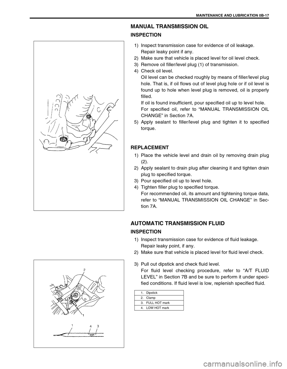
3) Remove oil filler/level plug (1) of transmission.
4) Check oil level.
Oil level can be checked roughly by means of filler/level plug
hole. That is, if oil flows out of level plug hole or if oil level is
found up to hole when level plug is removed, oil is properly
filled.
If oil is found insufficient, pour specified oil up to level hole.
For specified oil, refer to “MANUAL TRANSMISSION OIL
CHANGE” in Section 7A.
5) Apply sealant to filler/level plug and tighten it to specified
torque.
REPLACEMENT
1) Place the vehicle level and drain oil by removing drain plug
(2).
2) Apply sealant to drain plug after cleaning it and tighten drain
plug to specified torque.
3) Pour specified oil up to level hole.
4) Tighten filler plug to specified torque.
For recommended oil, its amount and tightening torque data,
refer to “MANUAL TRANSMISSION OIL CHANGE” in Sec-
tion 7A.
AUTOMATIC TRANSMISSION FLUID
INSPECTION
1) Inspect transmission case for evidence of fluid leakage.
Repair leaky point, if any.
2) Make sure that vehicle is placed level for fluid level check.
3) Pull out dipstick and check fluid level.
For fluid level checking procedure, refer to “A/T FLUID
LEVEL” in Section 7B and be sure to perform it under speci-
fied conditions. If fluid level is low, replenish specified fluid.
1. Dipstick
2. Clamp
3. FULL HOT mark
4. LOW HOT mark
Page 47 of 698
0B-18 MAINTENANCE AND LUBRICATION
REPLACEMENT
1) Inspect transmission case for evidence of fluid leakage.
Repair leaky point, if any.
2) Make sure that vehicle is placed level for fluid level check.
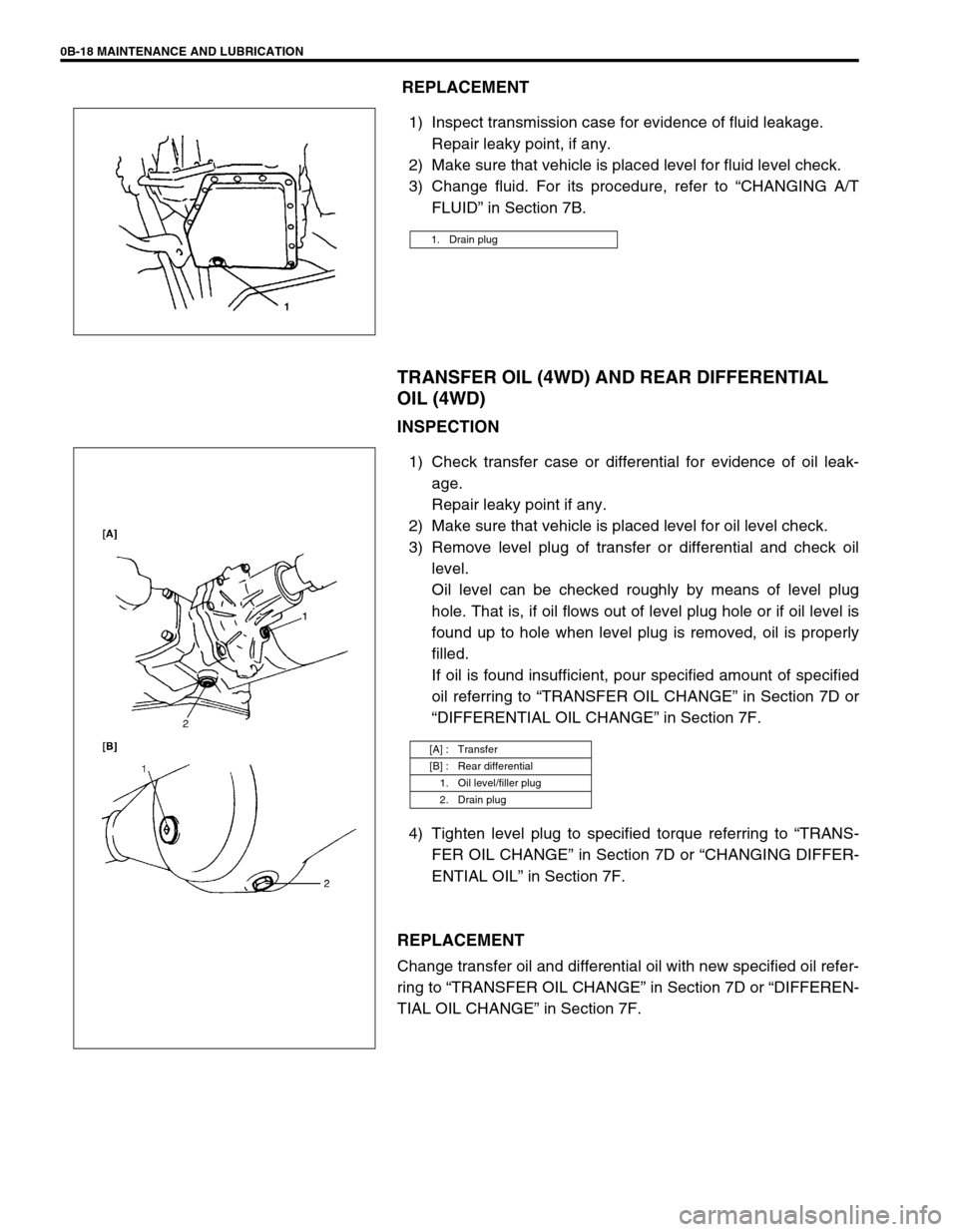
3) Change fluid. For its procedure, refer to “CHANGING A/T
FLUID” in Section 7B.
TRANSFER OIL (4WD) AND REAR DIFFERENTIAL
OIL (4WD)
INSPECTION
1) Check transfer case or differential for evidence of oil leak-
age.
Repair leaky point if any.
2) Make sure that vehicle is placed level for oil level check.
3) Remove level plug of transfer or differential and check oil
level.
Oil level can be checked roughly by means of level plug
hole. That is, if oil flows out of level plug hole or if oil level is
found up to hole when level plug is removed, oil is properly
filled.
If oil is found insufficient, pour specified amount of specified
oil referring to “TRANSFER OIL CHANGE” in Section 7D or
“DIFFERENTIAL OIL CHANGE” in Section 7F.
4) Tighten level plug to specified torque referring to “TRANS-
FER OIL CHANGE” in Section 7D or “CHANGING DIFFER-
ENTIAL OIL” in Section 7F.
REPLACEMENT
Change transfer oil and differential oil with new specified oil refer-
ring to “TRANSFER OIL CHANGE” in Section 7D or “DIFFEREN-
TIAL OIL CHANGE” in Section 7F.
1. Drain plug
[A] : Transfer
[B] : Rear differential
1. Oil level/filler plug
2. Drain plug
Page 234 of 698

REAR SUSPENSION 3E-21
2) Press-fit wheel bearing (1) with it’s seal side facing back
plate side using special tools and hydraulic press.
Special tool
(A) : 09913-76010
(B) : 09924-84510-004
3) Install bearing circlip (1) using special tool.
Special tool
(A) : 09900-06108
4) Install wheel sensor ring (if equipped with ABS).
Refer to “REAR WHEEL SENSOR RING” of Section 5E.
5) Install brake drum and wheel. For details, refer to “REAR
BRAKE DRUM” in Section 5.
REAR AXLE SHAFT AND WHEEL BEARING
(4WD VEHICLE)
REMOVAL
1) Hoist vehicle and remove rear wheels.
2) Remove rear brake drum. For details referring to Section 5.
3) Drain gear oil from rear axle housing by loosening drain plug
(1).
1. 8mm bolt
2. Level plug
Page 268 of 698
FRONT DRIVE SHAFT 4A-15
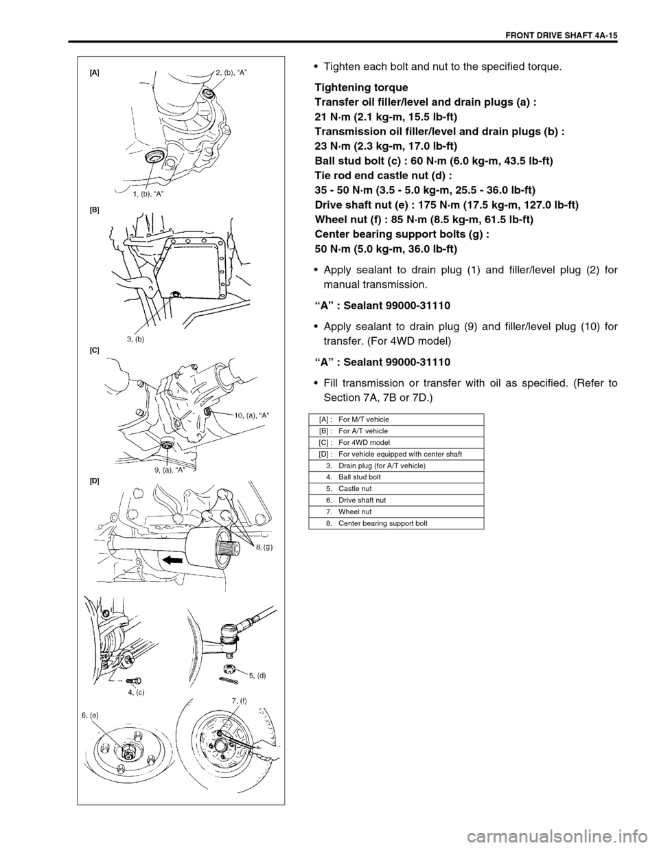
Tighten each bolt and nut to the specified torque.
Tightening torque
Transfer oil filler/level and drain plugs (a) :
21 N·m (2.1 kg-m, 15.5 lb-ft)
Transmission oil filler/level and drain plugs (b) :
23 N·m (2.3 kg-m, 17.0 lb-ft)
Ball stud bolt (c) : 60 N·m (6.0 kg-m, 43.5 lb-ft)
Tie rod end castle nut (d) :
35 - 50 N·m (3.5 - 5.0 kg-m, 25.5 - 36.0 lb-ft)
Drive shaft nut (e) : 175 N·m (17.5 kg-m, 127.0 lb-ft)
Wheel nut (f) : 85 N·m (8.5 kg-m, 61.5 lb-ft)
Center bearing support bolts (g) :
50 N·m (5.0 kg-m, 36.0 lb-ft)
Apply sealant to drain plug (1) and filler/level plug (2) for
manual transmission.
“A” : Sealant 99000-31110
Apply sealant to drain plug (9) and filler/level plug (10) for
transfer. (For 4WD model)
“A” : Sealant 99000-31110
Fill transmission or transfer with oil as specified. (Refer to
Section 7A, 7B or 7D.)
[A] : For M/T vehicle
[B] : For A/T vehicle
[C] : For 4WD model
[D] : For vehicle equipped with center shaft
3. Drain plug (for A/T vehicle)
4. Ball stud bolt
5. Castle nut
6. Drive shaft nut
7. Wheel nut
8. Center bearing support bolt
Page 269 of 698

4A-16 FRONT DRIVE SHAFT
TIGHTENING TORQUE SPECIFICATION
REQUIRED SERVICE MATERIAL
SPECIAL TOOL
Fastening portionTightening torque
Nm kg-m lb-ft
Transfer oil filler/level and drain plugs 21 2.1 15.5
Transmission oil filler/level and drain plugs 23 2.3 17.0
Ball stud bolt 60 6.0 43.5
Tie rod end castle nut 35 - 50 3.5 - 5.0 25.5 - 36.0
Drive shaft nut 175 17.5 127.0
Wheel nut 85 8.5 61.5
Center bearing support bolts 50 5.0 36.0
MaterialRecommended SUZUKI product
(Part Number)Use
Lithium grease SUZUKI SUPER GREASE A
(99000-25010)Oil seal lips
Sealant SUZUKI BOND NO. 1215
(99000-31110)Oil drain and filler plug for manual
transmission or transfer
09913-65210 09900-06107 09900-06108
Tie-rod end remover Snap ring pliers (Open
type)Snap ring pliers (Closing
type)
Page 277 of 698
5-4 BRAKES
DIAGNOSIS
ROAD TESTING BRAKES
Brakes should be tested on dry, clean, smooth and reasonably level roadway which is not crowned. Road test
brakes by making brake applications with both light and heavy pedal forces at various speeds to determine if the
vehicle stops evenly and effectively. Also drive vehicle to see if it leads to one side or the other without brake
application. If it does, check the tire pressure, front end alignment and front suspension attachments for loose-
ness. See diagnosis table for other causes.
BRAKE FLUID LEAKS
Check the master cylinder fluid levels. While a slight drop in reservoir level does result from normal lining wear,
an abnormally low level indicates a leak in the system. In such a case, check the entire brake system for leak-
age. If even a slight evidence of leakage is noted, the cause should be corrected or defective parts should be
replaced.
SUBSTANDARD OR CONTAMINATED BRAKE FLUID
Improper brake fluid, mineral oil or water in the fluid may cause the brake fluid to boil or the rubber components
in the hydraulic system to deteriorate.
If primary piston cups are swollen, then rubber parts have deteriorated. This deterioration may also be evi-
denced by swollen wheel cylinder piston cups on the drum brake wheels.
If deterioration of rubber is evident, disassemble all hydraulic parts and wash with alcohol. Dry these parts with
compressed air before assembly to keep alcohol out of the system. Replace all rubber parts in the system,
including hoses. Also, when working on the brake mechanisms, check for fluid on the linings.
If excessive fluid is found, replace the pads.
If master cylinder piston seals are satisfactory, check for leakage or excessive heat conditions. If leakage is not
found, drain fluid, flush with brake fluid, refill and bleed system.
The system must be flushed if there is any doubt as to the grade of fluid in the system or if fluid has been used
which contained parts that have been subjected to contaminated fluid.