2000 SUZUKI SWIFT clock
[x] Cancel search: clockPage 90 of 698

AIR CONDITIONING (OPTIONAL) 1B-25
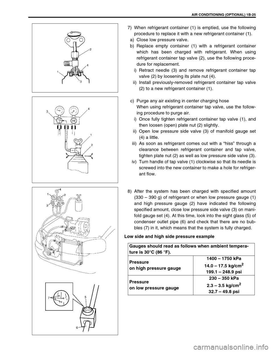
7) When refrigerant container (1) is emptied, use the following
procedure to replace it with a new refrigerant container (1).
a) Close low pressure valve.
b) Replace empty container (1) with a refrigerant container
which has been charged with refrigerant. When using
refrigerant container tap valve (2), use the following proce-
dure for replacement.
i) Retract needle (3) and remove refrigerant container tap
valve (2) by loosening its plate nut (4).
ii) Install previously-removed refrigerant container tap valve
(2) to a new refrigerant container (1).
c) Purge any air existing in center charging hose
When using refrigerant container tap valve, use the follow-
ing procedure to purge air.
i) Once fully tighten refrigerant container tap valve (1), and
then loosen (open) plate nut (2) slightly.
ii) Open low pressure side valve (3) of manifold gauge set
(4) a little.
iii) As soon as refrigerant comes out with a “hiss” through a
clearance between refrigerant container and tap valve,
tighten plate nut (2) as well as low pressure side valve (3).
iv) Turn handle of tap valve (1) clockwise so that its needle is
screwed into the new container to make a hole for refriger-
ant flow.
8) After the system has been charged with specified amount
(330 – 390 g) of refrigerant or when low pressure gauge (1)
and high pressure gauge (2) have indicated the following
specified amount, close low pressure side valve (3) on mani-
fold gauge set (4). At this time, look into the sight glass (5) of
condenser outlet pipe (6) and check that there are no bub-
bles (7) in it, which means that the system is fully charged.
Low side and high side pressure example
Gauges should read as follows when ambient tempera-
ture is 30°C (86 °F).
Pressure
on high pressure gauge1400 – 1750 kPa
14.0 – 17.5 kg/cm
2
199.1 – 248.9 psi
Pressure
on low pressure gauge230 – 350 kPa
2.3 – 3.5 kg/cm
2
32.7 – 49.8 psi
Page 179 of 698

3C-6 STEERING WHEEL AND COLUMN
STEERING WHEEL
REMOVAL
1) Remove driver air bag (inflator) module from steering wheel.
Refer to “DRIVER AIR BAG (INFLATOR) MODULE”.
2) Remove steering shaft nut.
3) Make alignment marks (1) on steering wheel and shaft for a
guide during reinstallation.
4) Remove steering wheel (1) with special tool.
Special tool
(A) : 09944-36011 CAUTION:
Removal of the steering wheel allows the contact coil to
turn freely but do not turn the contact coil (on the combi-
nation switch) more than allowable number of turns
(about two and a half turns from the center position
clockwise or counterclockwise respectively), or coil will
break.
CAUTION:
Do not hammer the end of the shaft. Hammering it will
loosen the plastic shear pins which maintain the column
length and impair the collapsible design of the column.
Page 180 of 698

STEERING WHEEL AND COLUMN 3C-7
INSTALLATION
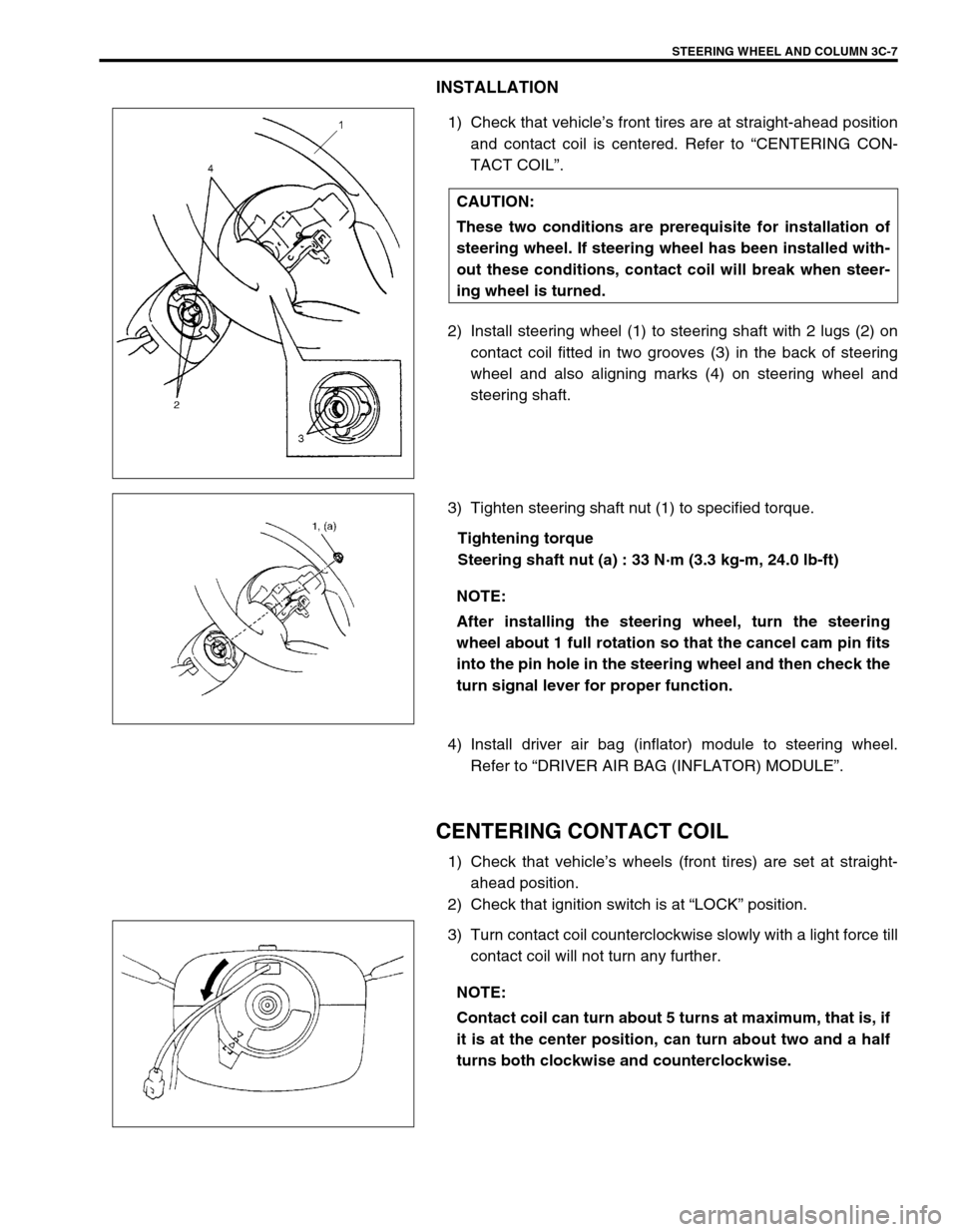
1) Check that vehicle’s front tires are at straight-ahead position
and contact coil is centered. Refer to “CENTERING CON-
TACT COIL”.
2) Install steering wheel (1) to steering shaft with 2 lugs (2) on
contact coil fitted in two grooves (3) in the back of steering
wheel and also aligning marks (4) on steering wheel and
steering shaft.
3) Tighten steering shaft nut (1) to specified torque.
Tightening torque
Steering shaft nut (a) : 33 N·m (3.3 kg-m, 24.0 lb-ft)
4) Install driver air bag (inflator) module to steering wheel.
Refer to “DRIVER AIR BAG (INFLATOR) MODULE”.
CENTERING CONTACT COIL
1) Check that vehicle’s wheels (front tires) are set at straight-
ahead position.
2) Check that ignition switch is at “LOCK” position.
3) Turn contact coil counterclockwise slowly with a light force till
contact coil will not turn any further. CAUTION:
These two conditions are prerequisite for installation of
steering wheel. If steering wheel has been installed with-
out these conditions, contact coil will break when steer-
ing wheel is turned.
NOTE:
After installing the steering wheel, turn the steering
wheel about 1 full rotation so that the cancel cam pin fits
into the pin hole in the steering wheel and then check the
turn signal lever for proper function.
NOTE:
Contact coil can turn about 5 turns at maximum, that is, if
it is at the center position, can turn about two and a half
turns both clockwise and counterclockwise.
Page 181 of 698

3C-8 STEERING WHEEL AND COLUMN
4) From the position where contact coil became unable to turn
any further (it stopped), turn it back clockwise about two and
a half rotations and align center mark (1) with alignment
mark.
CONTACT COIL AND COMBINATION SWITCH
ASSEMBLY
REMOVAL
1) Remove steering wheel from steering column referring to
“STEERING WHEEL” in this section.
2) Remove steering column hole cover (1).
3) Remove steering column cover screws (1).
4) Separate upper cover (2) and lower cover (3), then remove
them.
CAUTION:
Do not turn contact coil (on combination switch) more
than allowable number of turns (about two and a half
turns from the center position clockwise or counter-
clockwise respectively), or coil will break.
1
Page 281 of 698

5-8 BRAKES
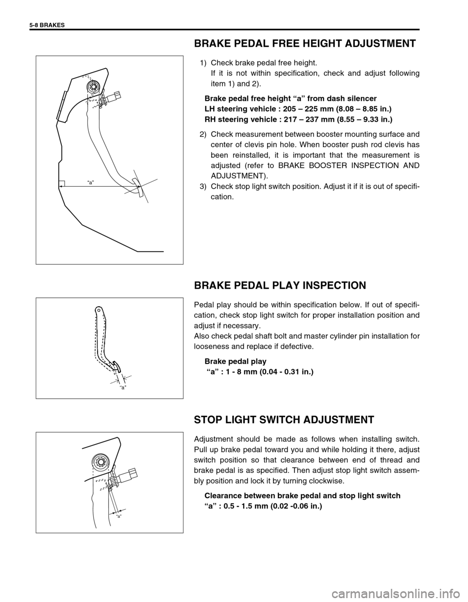
BRAKE PEDAL FREE HEIGHT ADJUSTMENT
1) Check brake pedal free height.
If it is not within specification, check and adjust following
item 1) and 2).
Brake pedal free height “a” from dash silencer
LH steering vehicle : 205 – 225 mm (8.08 – 8.85 in.)
RH steering vehicle : 217 – 237 mm (8.55 – 9.33 in.)
2) Check measurement between booster mounting surface and
center of clevis pin hole. When booster push rod clevis has
been reinstalled, it is important that the measurement is
adjusted (refer to BRAKE BOOSTER INSPECTION AND
ADJUSTMENT).
3) Check stop light switch position. Adjust it if it is out of specifi-
cation.
BRAKE PEDAL PLAY INSPECTION
Pedal play should be within specification below. If out of specifi-
cation, check stop light switch for proper installation position and
adjust if necessary.
Also check pedal shaft bolt and master cylinder pin installation for
looseness and replace if defective.
Brake pedal play
“a” : 1 - 8 mm (0.04 - 0.31 in.)
STOP LIGHT SWITCH ADJUSTMENT
Adjustment should be made as follows when installing switch.
Pull up brake pedal toward you and while holding it there, adjust
switch position so that clearance between end of thread and
brake pedal is as specified. Then adjust stop light switch assem-
bly position and lock it by turning clockwise.
Clearance between brake pedal and stop light switch
“a” : 0.5 - 1.5 mm (0.02 -0.06 in.)
“a”
“a”
Page 510 of 698

ENGINE MECHANICAL (M13 ENGINE) 6A1-9
VALVE LASH (CLEARANCE)
INSPECTION
1) Remove negative cable at battery.
2) Remove cylinder head cover referring to “CYLINDER HEAD
COVER”.
3) Remove right side engine cover if necessary.
4) Using 17 mm wrench, turn crankshaft pulley (1) clockwise
until cam lobes (2) become perpendicular to shim faces (3)
at valves “1” and “7” as shown in figure.
5) Check valve lashes with thickness gauge (4) according to
the following procedure.
a) Check valve lashes at valves “1” and “7”.
b) Turn camshafts by 90° (by turning crankshaft with wrench).
c) Make sure that cam lobes are perpendicular to shim faces
at valves to be checked (in this case, “3” and “8”), if not,
adjust it by turning crankshaft. Check valve lashes.
d) In the same manner as b) – c), check valve lashes at valves
“4” and “6”.
e) In the same manner as b) – c) again, check valve lashes at
valves “2” and “5”.
Valve clearance specification
If valve lash is out of specification, record valve lash and adjust it
to specification by replacing shim.
REPLACEMENT OF SHIM
1) Close the valve whose shim (2) is to be replaced by turning
crankshaft, then turn tappet (3) till its cut section (1) faces
inside as shown in figure.
2) Lift down the it valve by turning crankshaft to 180°.
3) Hold tappet at that position using special tool as follows.
a) Remove its housing bolts.When cold
(Coolant temperature
is 15 – 25°C
(59 – 77°F))When hot
(Coolant temperature
is 60 – 68°C
(140 – 154°F))
Intake 0.18 – 0.22 mm
(0.007 – 0.009 in.)0.21 – 0.27 mm
(0.008 – 0.011 in.)
Exhaust 0.28 – 0.32 mm
(0.011 – 0.013 in.)0.30 – 0.36 mm
(0.012 – 0.014 in.)
Page 511 of 698

6A1-10 ENGINE MECHANICAL (M13 ENGINE)
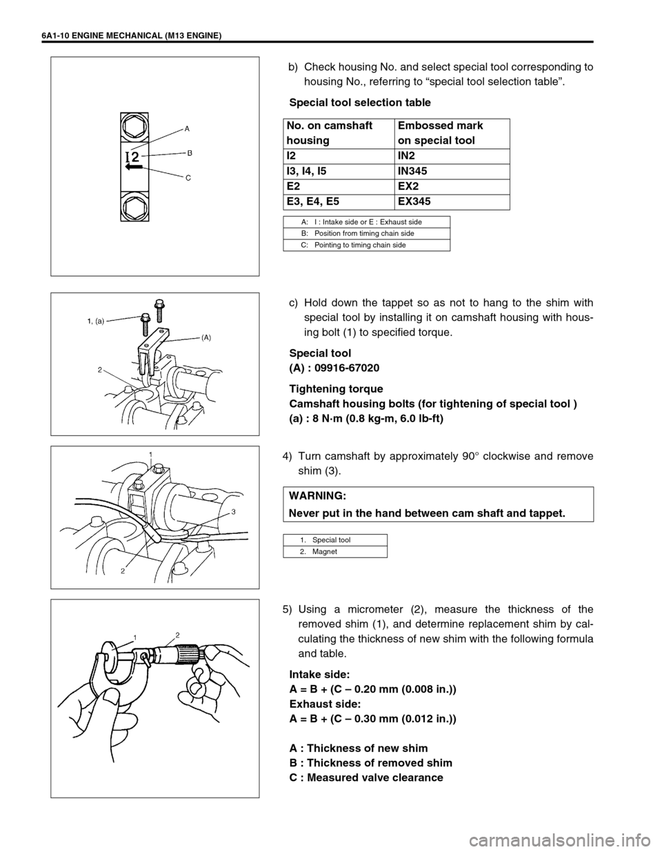
b) Check housing No. and select special tool corresponding to
housing No., referring to “special tool selection table”.
Special tool selection table
c) Hold down the tappet so as not to hang to the shim with
special tool by installing it on camshaft housing with hous-
ing bolt (1) to specified torque.
Special tool
(A) : 09916-67020
Tightening torque
Camshaft housing bolts (for tightening of special tool )
(a) : 8 N·m (0.8 kg-m, 6.0 lb-ft)
4) Turn camshaft by approximately 90° clockwise and remove
shim (3).
5) Using a micrometer (2), measure the thickness of the
removed shim (1), and determine replacement shim by cal-
culating the thickness of new shim with the following formula
and table.
Intake side:
A = B + (C – 0.20 mm (0.008 in.))
Exhaust side:
A = B + (C – 0.30 mm (0.012 in.))
A : Thickness of new shim
B : Thickness of removed shim
C : Measured valve clearance No. on camshaft
housingEmbossed mark
on special tool
I2 IN2
I3, I4, I5 IN345
E2 EX2
E3, E4, E5 EX345
A: I : Intake side or E : Exhaust side
B: Position from timing chain side
C: Pointing to timing chain side
WARNING:
Never put in the hand between cam shaft and tappet.
1. Special tool
2. Magnet
Page 512 of 698

ENGINE MECHANICAL (M13 ENGINE) 6A1-11
For example of intake side :
When thickness of removed shim is 2.40 mm (0.095 in.), and
measured valve clearance is 0.45 mm (0.018 in.).
A = 2.40 mm (0.094 in.) + (0.45 mm (0.018 in.) – 0.20 mm (0.008
in.)) = 2.65 mm (0.104 in.)
Calculated thickness of new shim = 2.65 mm (0.104 in.)
6) Select new shim No. (1) with a thickness as close as possi-
ble to calculated valve.
Available new shims No.
7) Install new shim facing shim No. side with tappet.
8) Lift valve by turning crankshaft counterclockwise (in opposite
direction against above Step 4) and remove special tool.
Special tool
(A) : 09916-6702Thickness
mm (in.)Shim
No.Thickness
mm (in.)Shim
No.
2.18 (0.0856) 218 2.68 (0.1055) 268
2.20 (0.0866) 220 2.70 (0.1063) 270
2.23 (0.0878) 223 2.73 (0.1075) 273
2.25 (0.0886) 225 2.75 (0.1083) 275
2.28 (0.0898) 228 2.78 (0.1095) 278
2.30 (0.0906) 230 2.80 (0.1102) 280
2.33 (0.0917) 233 2.83 (0.1114) 283
2.35 (0.0925) 235 2.85 (0.1122) 285
2.38 (0.0937) 238 2.88 (0.1134) 288
2.40 (0.0945) 240 2.90 (0.1142) 290
2.43 (0.0957) 243 2.93 (0.1154) 293
2.45 (0.0965) 245 2.75 (0.1161) 295
2.48 (0.0976) 248 2.98 (0.1173) 298
2.50 (0.0984) 250 3.00 (0.1181) 300
2.53 (0.0996) 253
2.55 (0.1004) 255
2.58 (0.1016) 258
2.60 (0.1024) 260
2.63 (0.1035) 263
2.65 (0.1043) 265
1. Tappet
2. Camshaft