Page 539 of 698
6A1-38 ENGINE MECHANICAL (M13 ENGINE)
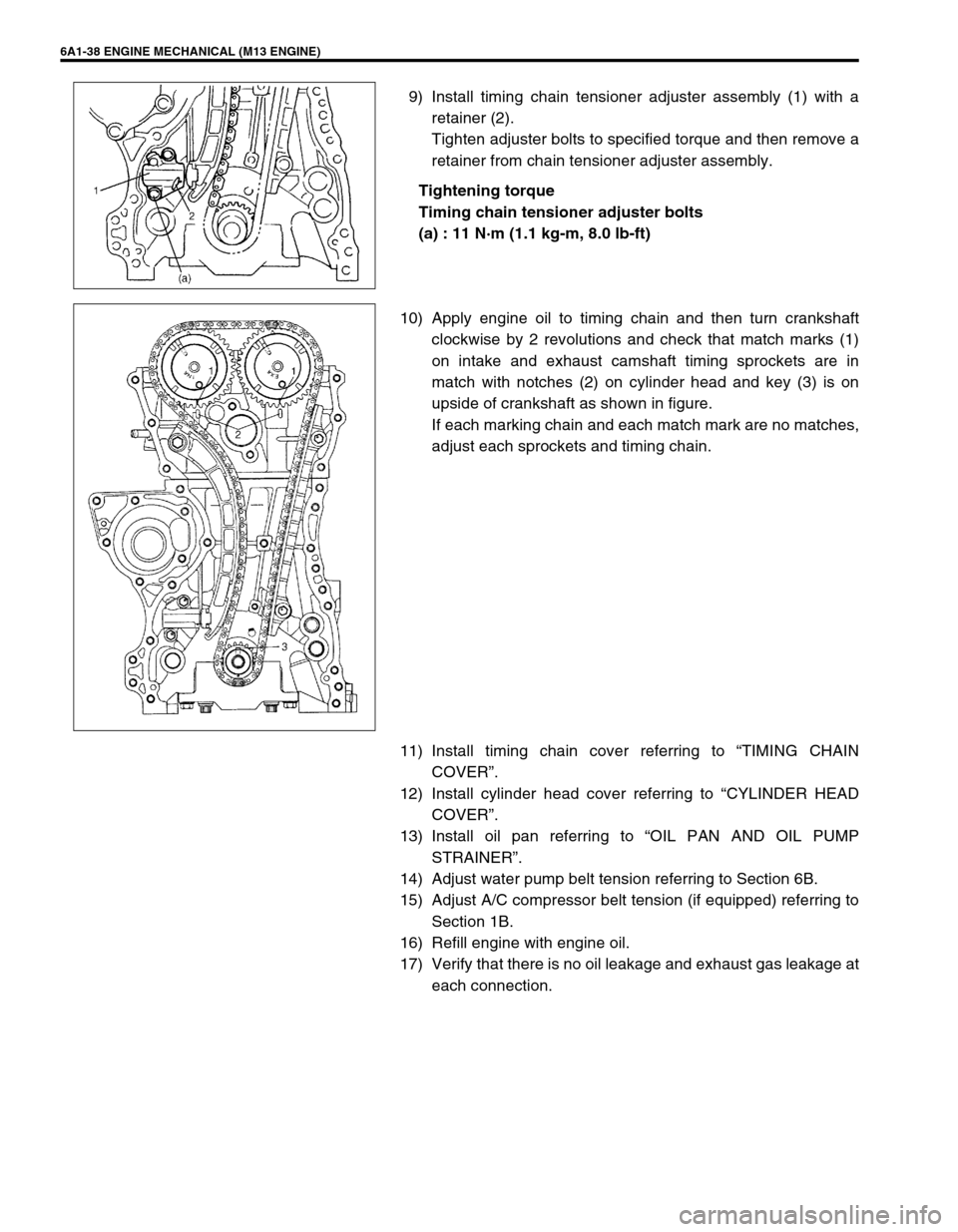
9) Install timing chain tensioner adjuster assembly (1) with a
retainer (2).
Tighten adjuster bolts to specified torque and then remove a
retainer from chain tensioner adjuster assembly.
Tightening torque
Timing chain tensioner adjuster bolts
(a) : 11 N·m (1.1 kg-m, 8.0 lb-ft)
10) Apply engine oil to timing chain and then turn crankshaft
clockwise by 2 revolutions and check that match marks (1)
on intake and exhaust camshaft timing sprockets are in
match with notches (2) on cylinder head and key (3) is on
upside of crankshaft as shown in figure.
If each marking chain and each match mark are no matches,
adjust each sprockets and timing chain.
11) Install timing chain cover referring to “TIMING CHAIN
COVER”.
12) Install cylinder head cover referring to “CYLINDER HEAD
COVER”.
13) Install oil pan referring to “OIL PAN AND OIL PUMP
STRAINER”.
14) Adjust water pump belt tension referring to Section 6B.
15) Adjust A/C compressor belt tension (if equipped) referring to
Section 1B.
16) Refill engine with engine oil.
17) Verify that there is no oil leakage and exhaust gas leakage at
each connection.
Page 596 of 698
ENGINE COOLING 6B-7
ENGINE COOLING SYSTEM INSPECTION
AND SERVICE
1) Check cooling system for leakage or damage.
2) Wash radiator cap and filler neck with clean water by remov-
ing radiator cap when engine is cold.
3) Check coolant for proper level and freeze protection.
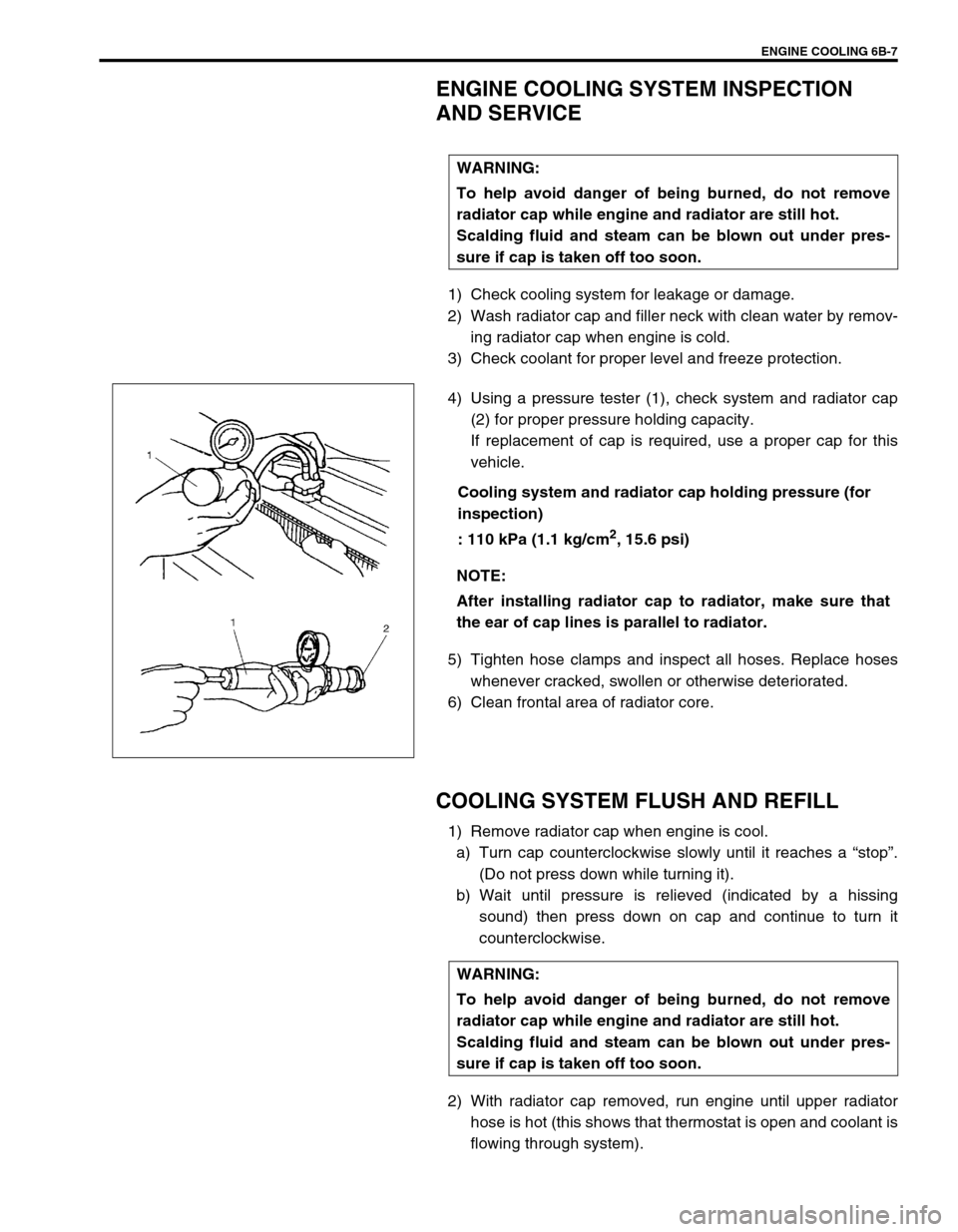
4) Using a pressure tester (1), check system and radiator cap
(2) for proper pressure holding capacity.
If replacement of cap is required, use a proper cap for this
vehicle.
Cooling system and radiator cap holding pressure (for
inspection)
: 110 kPa (1.1 kg/cm
2, 15.6 psi)
5) Tighten hose clamps and inspect all hoses. Replace hoses
whenever cracked, swollen or otherwise deteriorated.
6) Clean frontal area of radiator core.
COOLING SYSTEM FLUSH AND REFILL
1) Remove radiator cap when engine is cool.
a) Turn cap counterclockwise slowly until it reaches a “stop”.
(Do not press down while turning it).
b) Wait until pressure is relieved (indicated by a hissing
sound) then press down on cap and continue to turn it
counterclockwise.
2) With radiator cap removed, run engine until upper radiator
hose is hot (this shows that thermostat is open and coolant is
flowing through system). WARNING:
To help avoid danger of being burned, do not remove
radiator cap while engine and radiator are still hot.
Scalding fluid and steam can be blown out under pres-
sure if cap is taken off too soon.
NOTE:
After installing radiator cap to radiator, make sure that
the ear of cap lines is parallel to radiator.
WARNING:
To help avoid danger of being burned, do not remove
radiator cap while engine and radiator are still hot.
Scalding fluid and steam can be blown out under pres-
sure if cap is taken off too soon.
Page 649 of 698
6E1-28 ENGINE AND EMISSION CONTROL SYSTEM
THROTTLE POSITION SENSOR (TP SENSOR)
INSPECTION
1) Disconnect negative cable at battery and connector from IAT
sensor.
2) Remove air cleaner assembly with air cleaner outlet hose
and disconnect TP sensor connector.
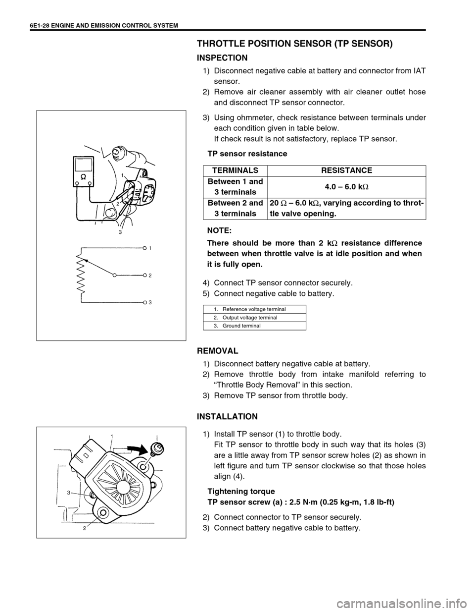
3) Using ohmmeter, check resistance between terminals under
each condition given in table below.
If check result is not satisfactory, replace TP sensor.
TP sensor resistance
4) Connect TP sensor connector securely.
5) Connect negative cable to battery.
REMOVAL
1) Disconnect battery negative cable at battery.
2) Remove throttle body from intake manifold referring to
“Throttle Body Removal” in this section.
3) Remove TP sensor from throttle body.
INSTALLATION
1) Install TP sensor (1) to throttle body.
Fit TP sensor to throttle body in such way that its holes (3)
are a little away from TP sensor screw holes (2) as shown in
left figure and turn TP sensor clockwise so that those holes
align (4).
Tightening torque
TP sensor screw (a) : 2.5 N·m (0.25 kg-m, 1.8 lb-ft)
2) Connect connector to TP sensor securely.
3) Connect battery negative cable to battery.TERMINALS RESISTANCE
Between 1 and
3 terminals4.0 – 6.0 k
Ω
Between 2 and
3 terminals20
Ω – 6.0 k
Ω, varying according to throt-
tle valve opening.
NOTE:
There should be more than 2 k
Ω resistance difference
between when throttle valve is at idle position and when
it is fully open.
1. Reference voltage terminal
2. Output voltage terminal
3. Ground terminal
Page 680 of 698
6G-8 CRANKING SYSTEM
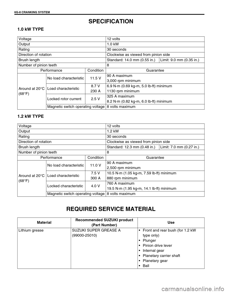
SPECIFICATION
1.0 kW TYPE
1.2 kW TYPE
REQUIRED SERVICE MATERIAL
Voltage 12 volts
Output 1.0 kW
Rating 30 seconds
Direction of rotation Clockwise as viewed from pinion side
Brush length Standard: 14.0 mm (0.55 in.) Limit: 9.0 mm (0.35 in.)
Number of pinion teeth 8
Performance Condition Guarantee
Around at 20°C
(68°F)No load characteristic 11.5 V90 A maximum
3,000 rpm minimum
Load characteristic8.7 V
230 A6.9 N·m (0.69 kg-m, 5.0 lb-ft) minimum
1130 rpm minimum
Locked rotor current 2.5 V325 A maximum
8.2 N·m (0.82 kg-m, 6.0 lb-ft) minimum
Magnetic switch operating voltage 8 volts maximum
Voltage 12 volts
Output 1.2 kW
Rating 30 seconds
Direction of rotation Clockwise as viewed from pinion side
Brush length Standard: 12.3 mm (0.48 in.) Limit: 7.0 mm (0.27 in.)
Number of pinion teeth 8
Performance Condition Guarantee
Around at 20°C
(68°F)No load characteristic 11.0 V90 A maximum
2,500 rpm minimum
Load characteristic7.5 V
300 A10.5 N·m (1.05 kg-m, 7.59 lb-ft) minimum
880 rpm minimum
Locked characteristic 4.0 V760 A maximum
19.5 N·m (1.95 kg-m, 14.1 lb-ft) minimum
Magnetic switch operating voltage 8 volts maximum
MaterialRecommended SUZUKI product
(Part Number)Use
Lithium grease SUZUKI SUPER GREASE A
(99000-25010)Front and rear bush (for 1.2 kW
type only)
Plunger
Pinion drive lever
Internal gear
Planetary carrier shaft
Planetary gear
Ball
Page 694 of 698
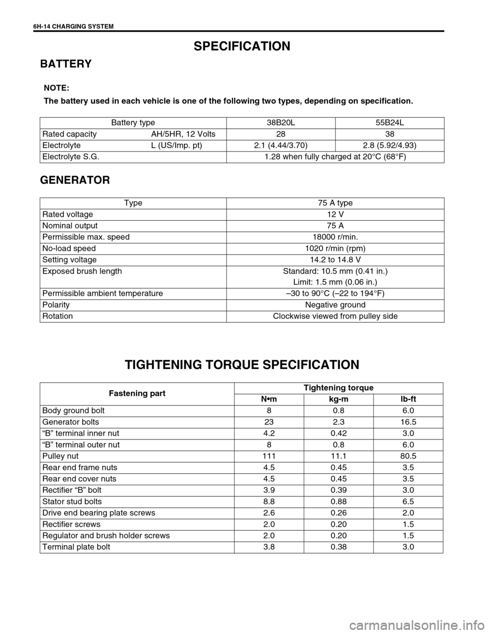
6H-14 CHARGING SYSTEM
SPECIFICATION
BATTERY
GENERATOR
TIGHTENING TORQUE SPECIFICATION
NOTE:
The battery used in each vehicle is one of the following two types, depending on specification.
Battery type 38B20L 55B24L
Rated capacity AH/5HR, 12 Volts 28 38
Electrolyte L (US/Imp. pt) 2.1 (4.44/3.70) 2.8 (5.92/4.93)
Electrolyte S.G. 1.28 when fully charged at 20°C (68°F)
Type 75 A type
Rated voltage 12 V
Nominal output 75 A
Permissible max. speed 18000 r/min.
No-load speed 1020 r/min (rpm)
Setting voltage 14.2 to 14.8 V
Exposed brush length Standard: 10.5 mm (0.41 in.)
Limit: 1.5 mm (0.06 in.)
Permissible ambient temperature–30 to 90°C (–22 to 194°F)
Polarity Negative ground
Rotation Clockwise viewed from pulley side
Fastening partTightening torque
Nm kg-m lb-ft
Body ground bolt 8 0.8 6.0
Generator bolts 23 2.3 16.5
“B” terminal inner nut 4.2 0.42 3.0
“B” terminal outer nut 8 0.8 6.0
Pulley nut 111 11.1 80.5
Rear end frame nuts 4.5 0.45 3.5
Rear end cover nuts 4.5 0.45 3.5
Rectifier “B” bolt 3.9 0.39 3.0
Stator stud bolts 8.8 0.88 6.5
Drive end bearing plate screws 2.6 0.26 2.0
Rectifier screws 2.0 0.20 1.5
Regulator and brush holder screws 2.0 0.20 1.5
Terminal plate bolt 3.8 0.38 3.0