2000 SUZUKI SWIFT jump start
[x] Cancel search: jump startPage 12 of 698

GENERAL INFORMATION 0A-9
Use care not to expose connectors and electrical parts
to water which will be a cause of a trouble.
Always be careful not to handle electrical parts (com-
puter, relay, etc.) in a rough manner or drop them.
PRECAUTIONS FOR CATALYTIC CONVERTER
For vehicles equipped with a catalytic converter, use only unleaded gasoline and be careful not to let a
large amount of unburned gasoline enter the converter or it can be damaged.
Conduct a spark jump test only when necessary, make it as short as possible, and do not open the
throttle.
Conduct engine compression checks within the shortest possible time.
Avoid situations which can result in engine misfire (e.g. starting the engine when the fuel tank is
nearly empty.)
PRECAUTION FOR INSTALLING MOBILE COMMUNICATION EQUIPMENT
When installing mobile communication equipment such as CB (Citizens-Band)-radio or cellular-tele-
phone, be sure to observe the following precautions.
Failure to follow cautions may adversely affect electronic control system.
Keep the antenna as far away as possible from the vehicle’s electronic control unit.
Keep the antenna feeder more than 20 cm (7.9 in) away from electronic control unit and its wire har-
nesses.
Do not run the antenna feeder parallel with other wire harnesses.
Confirm that the antenna and feeder are correctly adjusted.
Page 149 of 698

3B1-8 ELECTRICAL POWER STEERING (P/S) SYSTEM
DTC CHECK
USING SUZUKI SCAN TOOL
1) Turn ignition switch to OFF position.
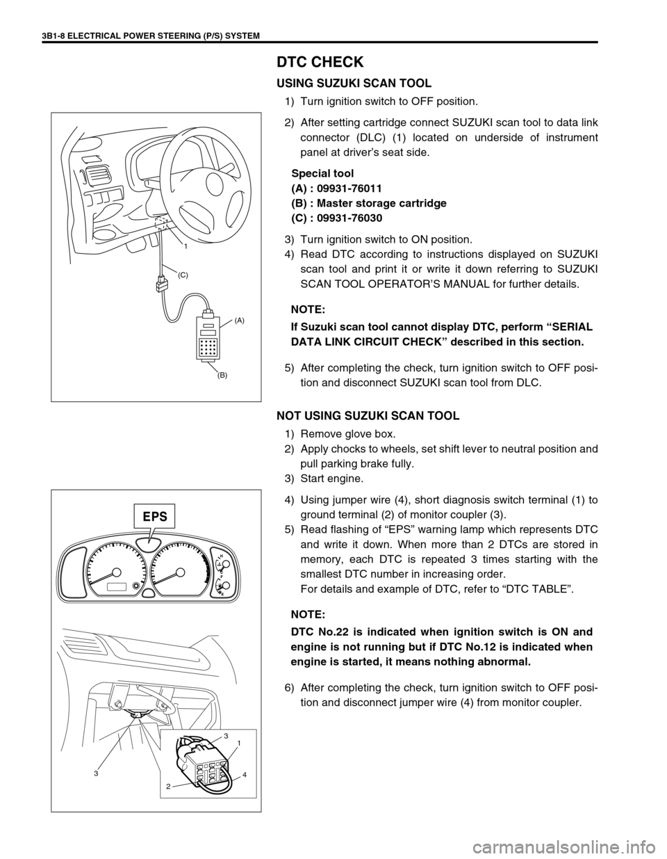
2) After setting cartridge connect SUZUKI scan tool to data link
connector (DLC) (1) located on underside of instrument
panel at driver’s seat side.
Special tool
(A) : 09931-76011
(B) : Master storage cartridge
(C) : 09931-76030
3) Turn ignition switch to ON position.
4) Read DTC according to instructions displayed on SUZUKI
scan tool and print it or write it down referring to SUZUKI
SCAN TOOL OPERATOR’S MANUAL for further details.
5) After completing the check, turn ignition switch to OFF posi-
tion and disconnect SUZUKI scan tool from DLC.
NOT USING SUZUKI SCAN TOOL
1) Remove glove box.
2) Apply chocks to wheels, set shift lever to neutral position and
pull parking brake fully.
3) Start engine.
4) Using jumper wire (4), short diagnosis switch terminal (1) to
ground terminal (2) of monitor coupler (3).
5) Read flashing of “EPS” warning lamp which represents DTC
and write it down. When more than 2 DTCs are stored in
memory, each DTC is repeated 3 times starting with the
smallest DTC number in increasing order.
For details and example of DTC, refer to “DTC TABLE”.
6) After completing the check, turn ignition switch to OFF posi-
tion and disconnect jumper wire (4) from monitor coupler. NOTE:
If Suzuki scan tool cannot display DTC, perform “SERIAL
DATA LINK CIRCUIT CHECK” described in this section.
(B)(A) (C)1
NOTE:
DTC No.22 is indicated when ignition switch is ON and
engine is not running but if DTC No.12 is indicated when
engine is started, it means nothing abnormal.
3
21
3
4
Page 681 of 698

CHARGING SYSTEM 6H-1
6F1
6F2
6G
6K
7A
6H
7B1
7C1
7D
7E
7F
8A
8B
8C
8D
8E
9
10
10A
10B
SECTION 6H
CHARGING SYSTEM
CONTENTS
GENERAL DESCRIPTION .............................. 6H-2
BATTERY ..................................................... 6H-2
CARRIER AND HOLD-DOWN ................. 6H-2
ELECTROLYTE FREEZING .................... 6H-2
SULFATION ............................................. 6H-2
BUILT-IN INDICATOR (IF EQUIPPED) ... 6H-2
CARE OF BATTERY ................................ 6H-3
GENERATOR .............................................. 6H-4
DIAGNOSIS ..................................................... 6H-5
BATTERY ..................................................... 6H-5
VISUAL INSPECTION.............................. 6H-5
HYDROMETER TEST.............................. 6H-5
GENERATOR .............................................. 6H-6
CHARGING INDICATOR LAMP
OPERATION ............................................ 6H-6
UNDERCHARGED BATTERY ................. 6H-7
OVERCHARGED BATTERY.................... 6H-8ON-VEHICLE SERVICE .................................. 6H-9
BATTERY .................................................... 6H-9
JUMP STARTING IN CASE OF
EMERGENCY .......................................... 6H-9
DISMOUNTING...................................... 6H-10
HANDLING............................................. 6H-10
REMOUNTING....................................... 6H-10
GENERATOR ............................................ 6H-10
GENERATOR BELT .............................. 6H-10
DISMOUNTING AND REMOUNTING ... 6H-11
DISASSEMBLY AND REASSEMBLY .... 6H-11
INSPECTION ......................................... 6H-12
SPECIFICATION ........................................... 6H-14
BATTERY .................................................. 6H-14
GENERATOR ............................................ 6H-14
TIGHTENING TORQUE SPECIFICATION.... 6H-14
WARNING:
For vehicles equipped with Supplemental Restraint (Air Bag) System:
Service on and around the air bag system components or wiring must be performed only by an
authorized SUZUKI dealer. Refer to “Air Bag System Components and Wiring Location View” under
“General Description” in air bag system section in order to confirm whether you are performing ser-
vice on or near the air bag system components or wiring. Please observe all WARNINGS and “Ser-
vice Precautions” under “On-Vehicle Service” in air bag system section before performing service
on or around the air bag system components or wiring. Failure to follow WARNINGS could result in
unintentional activation of the system or could render the system inoperative. Either of these two
conditions may result in severe injury.
Technical service work must be started at least 90 seconds after the ignition switch is turned to the
“LOCK” position and the negative cable is disconnected from the battery. Otherwise, the system
may be activated by reserve energy in the Sensing and Diagnostic Module (SDM).
Page 689 of 698

CHARGING SYSTEM 6H-9
ON-VEHICLE SERVICE
BATTERY
JUMP STARTING IN CASE OF EMERGENCY
WITH AUXILIARY (BOOSTER) BATTERY
Both booster and discharged battery should be treated carefully when using jumper cables. Follow procedure
outlined below, being careful not to cause sparks.
1) Set parking brake and place automatic transmission in PARK (NEUTRAL on manual transmission). Turn off
ignition, turn off lights and all other electrical loads.
2) Check electrolyte level. If it is below low level line, add distilled water.
3) Attach end of one jumper cable to positive terminal of booster battery and the other end of the same cable to
positive terminal of discharged battery. (Use 12-volt battery only to jump start engine).
4) Attach one end of the remaining negative cable to negative terminal of booster battery, and the other end to
a solid engine ground (such as exhaust manifold) at least 45 cm (18 in.) away from battery of vehicle being
started.
5) Start engine of vehicle with booster battery and turn off electrical accessories. Then Start engine of the vehi-
cle with discharged battery.
6) Disconnect jumper cables in the exact reverse order.
WITH CHARGING EQUIPMENT
CAUTION:
If vehicle is manual transmission model and has a catalytic converter, do not push or tow it to start.
Damage to its emission system and/or to other parts may result.
WARNING:
Departure from these conditions or procedure described below could result in:
–Serious personal injury (particularly to eyes) or property damage from such causes as battery
explosion, battery acid, or electrical burns.
–Damage to electronic components of either vehicle.
Remove rings, watches, and other jewelry. Wear approved eye protection.
Be careful so that metal tools or jumper cables do not contact positive battery terminal (or metal in
contact with it) and any other metal on vehicle, because a short circuit could occur.
WARNING:
Do not connect negative cable directly to negative terminal of dead battery.
CAUTION:
When jump starting engine with charging equipment, be sure equipment used is 12-volt and negative
ground. Do not use 24-volt charging equipment. Using such equipment can cause serious damage to
electrical system or electronic parts.