2000 SUZUKI SWIFT Lights
[x] Cancel search: LightsPage 50 of 698

MAINTENANCE AND LUBRICATION 0B-21
STEERING
Check to ensure that steering wheel is free from instability, or abnormally heavy feeling.
Check that the vehicle does not wander or pull to one side.
ENGINE
Check that engine responds readily at all speeds.
Check that engine is free from abnormal noise and abnormal vibration.
BODY, WHEELS AND POWER TRANSMITTING SYSTEM
Check that body, wheels and power transmitting system are free from abnormal noise and abnormal vibration or
any other abnormal condition.
METERS AND GAUGE
Check that speedometer, odometer, fuel meter, temperature gauge, etc. are operating accurately.
LIGHTS
Check that all lights operate properly.
WINDSHIELD DEFROSTER
Periodically check that air comes out from defroster outlet when operating heater or air conditioning.
Set mode control lever to defroster position and fan switch lever to “HI” position for this check.
RECOMMENDED FLUIDS AND LUBRICANTS
Engine oil SE, SF, SG, SH or SJ grade (Refer to “ENGINE OIL AND OIL FILTER”
in this section for engine oil viscosity.)
Engine coolant
(Ethylene glycol base coolant)“Antifreeze/Anticorrosion coolant”
Brake fluid DOT 3
Manual transmission oil Refer to “M/T OIL CHANGE” in Section 7A.
Transfer oil (4WD) Refer to “TRANSFER OIL CHANGE” in Section 7D.
Differential oil (4WD) Refer to “DIFFERENTIAL OIL CHANGE” in Section 7F.
Automatic transmission fluid
An equivalent of DEXRON
®-III
Door hinges Engine oil or water resistance chassis grease
Hood latch assembly Engine oil or water resistance chassis grease
Key lock cylinder Spray lubricant
Page 101 of 698

1B-36 AIR CONDITIONING (OPTIONAL)
A/C SWITCH
REMOVAL AND INSTALLATION
Refer to “HEATER CONTROL ASSEMBLY” in Section 1A.
INSPECTION
Press A/C switch button and check if there is continuity
between terminals “A” and “B”.
Connect battery voltage (+) to terminal “C” and (–) to termi-
nal “A”, and then press A/C Switch button and check if indi-
cator lamp lights.
RADIATOR/CONDENSER COOLING FAN
MOTOR RELAY No.1, No.2 and No.3
INSPECTION
Refer to “RADIATOR FAN RELAY” in Section 6B.
COMPRESSOR
REMOVAL
1) Run engine at idle speed with air conditioning ON for 10 min-
utes. After that stop the engine.
2) Disconnect negative (–) cable at battery.
3) Recover refrigerant from refrigeration system by referring to
“RECOVERY” in this section.
4) Remove front bumper by referring to “FRONT BUMPER” in
Section 8.
5) Remove engine food cover (1) from vehicle body.
NOTE:
The amount of removed compressor oil must be mea-
sured for replenishing compressor oil.
Page 145 of 698

3B1-4 ELECTRICAL POWER STEERING (P/S) SYSTEM
DIAGNOSIS
The P/S system in this vehicle is controlled by P/S control module. P/S control module has an on-board diagnos-
tic system which detects a malfunction in this system.
When diagnosing troubles, be sure to have full understanding of the outline of “ON-BOARD DIAGNOSTIC SYS-
TEM” and each item in “PRECAUTION IN DIAGNOSING TROUBLE” and execute diagnosis according to “SYS-
TEM CHECK FLOW TABLE”.
ON-BOARD DIAGNOSTIC SYSTEM
P/S control module performs on-board diagnosis (self-diagnosis)
on the system and operates “EPS” warning lamp (1) (malfunction
indicator lamp) as follows.
Malfunction indicator lamp (“EPS” warning lamp) lights when
the ignition switch is turned to ON position (but the engine at
stop) regardless of the condition of P/S control system. This
is only to check the malfunction indicator lamp (“EPS” warn-
ing lamp) bulb and its circuit.
If the areas monitored by P/S control module is free from any
trouble after the engine start (while engine is running), mal-
function indicator lamp (“EPS” warning lamp) turns OFF.
When P/S control module detects a trouble which has
occurred in the areas it monitors, malfunction indicator lamp
(“EPS” warning lamp) turns ON while the engine is running
to warn the driver of such occurrence of trouble and at the
same time it stores the exact trouble area in memory inside
of P/S control module.
PRECAUTIONS IN DIAGNOSING TROUBLES
Take a note of DTC indicated first.
Be sure to read “PRECAUTIONS FOR ELECTRONIC CIRCUIT SERVICE” in Section 0A before inspection
and observe what is written there.
When two or more troubles have occurred, their DTCs are indicated 3 times each starting with the smallest
code number and up.
DTC C1122 (DTC No.22) (engine speed signal failure) is indicated when ignition switch is ON position and
engine is not running but if indication changes to a normal one when engine is started, it means nothing
abnormal.
As DTC is stored in memory of P/S control module, be sure to clear memory after repair by performing the
procedure described in “DTC CLEARANCE”.
1
Page 148 of 698

ELECTRICAL POWER STEERING (P/S) SYSTEM 3B1-7
CUSTOMER QUESTIONNAIRE (EXAMPLE)
MALFUNCTION INDICATOR LAMP
(“EPS” WARNING LAMP) CHECK
1) Turn ignition switch to ON position (but without running
engine), check that malfunction indicator lamp (“EPS” warn-
ing lamp) lights up. If lamp does not light up, go to “TABLE
A”. If lamp flashes, go to “TABLE B”.
2) Start engine and check that malfunction indictor lamp
(“CHECK ENGIE” light) turns OFF.
If lamp comes OFF, P/S system is in good condition.
Page 280 of 698

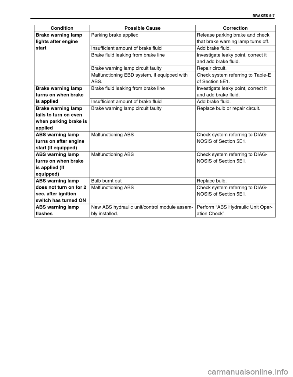
BRAKES 5-7
Brake warning lamp
lights after engine
startParking brake applied Release parking brake and check
that brake warning lamp turns off.
Insufficient amount of brake fluid Add brake fluid.
Brake fluid leaking from brake line Investigate leaky point, correct it
and add brake fluid.
Brake warning lamp circuit faulty Repair circuit.
Malfunctioning EBD system, if equipped with
ABS.Check system referring to Table-E
of Section 5E1.
Brake warning lamp
turns on when brake
is appliedBrake fluid leaking from brake line Investigate leaky point, correct it
and add brake fluid.
Insufficient amount of brake fluid Add brake fluid.
Brake warning lamp
fails to turn on even
when parking brake is
appliedBrake warning lamp circuit faulty Replace bulb or repair circuit.
ABS warning lamp
turns on after engine
start (If equipped)Malfunctioning ABS Check system referring to DIAG-
NOSIS of Section 5E1.
ABS warning lamp
turns on when brake
is applied (If
equipped)Malfunctioning ABS Check system referring to DIAG-
NOSIS of Section 5E1.
ABS warning lamp
does not turn on for 2
sec. after ignition
switch has turned ONBulb burnt out Replace bulb.
Malfunctioning ABS Check system referring to DIAG-
NOSIS of Section 5E1.
ABS warning lamp
flashesNew ABS hydraulic unit/control module assem-
bly installed.Perform “ABS Hydraulic Unit Oper-
ation Check”. Condition Possible Cause Correction
Page 287 of 698

5-14 BRAKES
5) If rear brake pressure is not within specification, adjust it by
changing bolt (2) position as follows.
If rear brake pressure is higher than specification, move bolt
(2) center side and if it is lower, out side.
Repeat steps 3) and 4) until rear brake pressure is within
specification.
After adjustment, be sure to torque nut (1) to specification.
Tightening torque
LSPV nut (a) : 25 N·m (2.5 kg-m, 18.0 lb-ft)
6) Upon completion of fluid pressure test, bleed brake system
and perform brake test.
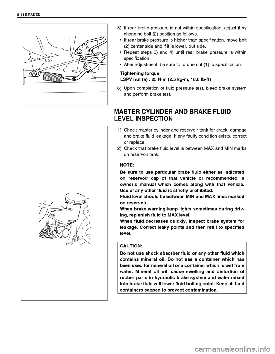
MASTER CYLINDER AND BRAKE FLUID
LEVEL INSPECTION
1) Check master cylinder and reservoir tank for crack, damage
and brake fluid leakage. If any faulty condition exists, correct
or replace.
2) Check that brake fluid level is between MAX and MIN marks
on reservoir tank.
2
1, (a)
NOTE:
Be sure to use particular brake fluid either as indicated
on reservoir cap of that vehicle or recommended in
owner’s manual which comes along with that vehicle.
Use of any other fluid is strictly prohibited.
Fluid level should be between MIN and MAX lines marked
on reservoir.
When brake warning lamp lights sometimes during driv-
ing, replenish fluid to MAX level.
When fluid decreases quickly, inspect brake system for
leakage. Correct leaky points and then refill to specified
level.
CAUTION:
Do not use shock absorber fluid or any other fluid which
contains mineral oil. Do not use a container which has
been used for mineral oil or a container which is wet from
water. Mineral oil will cause swelling and distortion of
rubber parts in hydraulic brake system and water mixed
into brake fluid will lower fluid boiling point. Keep all fluid
containers capped to prevent contamination.
MAX
MIN
Page 328 of 698

ANTILOCK BRAKE SYSTEM (ABS) 5E-3
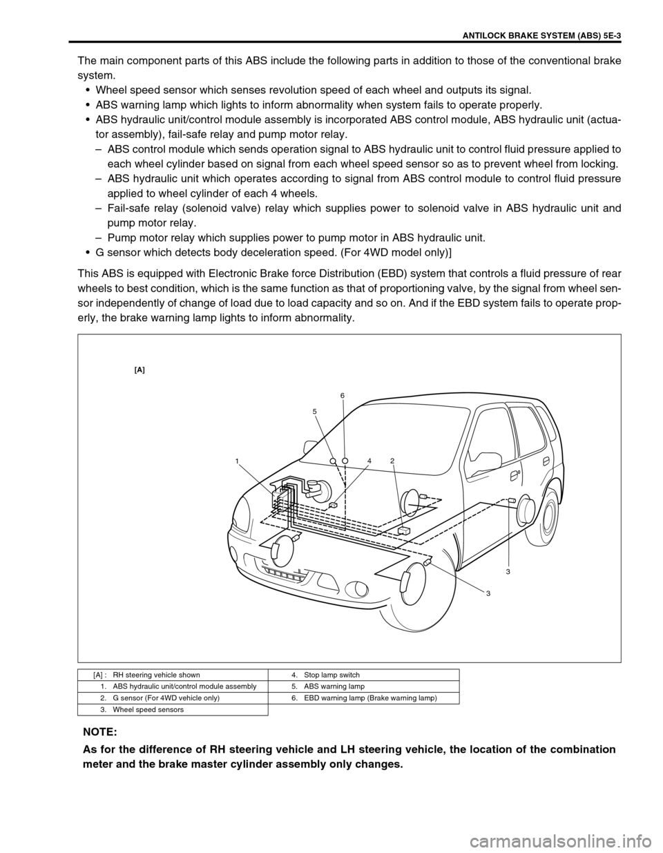
The main component parts of this ABS include the following parts in addition to those of the conventional brake
system.
Wheel speed sensor which senses revolution speed of each wheel and outputs its signal.
ABS warning lamp which lights to inform abnormality when system fails to operate properly.
ABS hydraulic unit/control module assembly is incorporated ABS control module, ABS hydraulic unit (actua-
tor assembly), fail-safe relay and pump motor relay.
–ABS control module which sends operation signal to ABS hydraulic unit to control fluid pressure applied to
each wheel cylinder based on signal from each wheel speed sensor so as to prevent wheel from locking.
–ABS hydraulic unit which operates according to signal from ABS control module to control fluid pressure
applied to wheel cylinder of each 4 wheels.
–Fail-safe relay (solenoid valve) relay which supplies power to solenoid valve in ABS hydraulic unit and
pump motor relay.
–Pump motor relay which supplies power to pump motor in ABS hydraulic unit.
G sensor which detects body deceleration speed. (For 4WD model only)]
This ABS is equipped with Electronic Brake force Distribution (EBD) system that controls a fluid pressure of rear
wheels to best condition, which is the same function as that of proportioning valve, by the signal from wheel sen-
sor independently of change of load due to load capacity and so on. And if the EBD system fails to operate prop-
erly, the brake warning lamp lights to inform abnormality.
[A] : RH steering vehicle shown 4. Stop lamp switch
1. ABS hydraulic unit/control module assembly 5. ABS warning lamp
2. G sensor (For 4WD vehicle only) 6. EBD warning lamp (Brake warning lamp)
3. Wheel speed sensors
156
2 4
33
[A]
NOTE:
As for the difference of RH steering vehicle and LH steering vehicle, the location of the combination
meter and the brake master cylinder assembly only changes.
Page 330 of 698

ANTILOCK BRAKE SYSTEM (ABS) 5E-5
ABS HYDRAULIC UNIT/CONTROL MODULE
ASSEMBLY
ABS control module is a component of ABS hydraulic unit/control
module assembly and has the following functions.
SELF-DIAGNOSIS FUNCTION
ABS control module diagnoses conditions of the system compo-
nent parts (whether or not there is any abnormality) all the time
and indicates the results (warning of abnormality occurrence and
DTC) through the ABS warning lamp as described below.
1) When ignition switch is turned ON, ABS warning lamp lights
for 2 seconds to check its bulb and circuit.
2) When no abnormality has been detected (the system is in
good condition), ABS warning lamp turns OFF after 2 sec-
onds.
3) When an abnormality in the system is detected, ABS warn-
ing lamp lights and the area where that abnormality lies is
stored in the memory of EEPROM in ABS control module.
4) When Diag. switch terminal (2) of diagnosis connector (1)
(monitor connector) is grounded, the abnormal area is output
as DTC. It is indicated by flashing of ABS warning lamp.
(Refer to the table below.)
5) For procedure to clear all DTC’s, refer to “DIAGNOSTIC
TROUBLE CODE CLEARANCE” in this section.
Also ABS control module turns ON EBD warning lamp (brake
warning lamp) depending on the trouble that detected by the
module and EBD warning lamp does not indicate DTC as well as
ABS warning lamp.
FAIL-SAFE FUNCTION
When an abnormality occurs (an abnormal DTC is detected),
ABS control module turns OFF the fail-safe relay which supplies
power to ABS hydraulic unit. Thus, with ABS not operating,
brakes function just like the brake system of the vehicle without
ABS.
SYSTEM CONDITIONABS WARNING LAMP
Diag. switch
terminal is
not groundedDiag. switch
terminal is
grounded
In good
condition
at presentNo trouble in the past OFF DTC 12
Trouble occurred in
the pastOFF History DTC
Abnormal-
ity exists
at presentNo trouble in the past ON Current DTC
Trouble occurred in
the pastONCurrent and
history DTCs
3. Ground terminal
4. Service wire
3 11
2
4