2000 SUZUKI SWIFT wheel bolt torque
[x] Cancel search: wheel bolt torquePage 41 of 698

0B-12 MAINTENANCE AND LUBRICATION
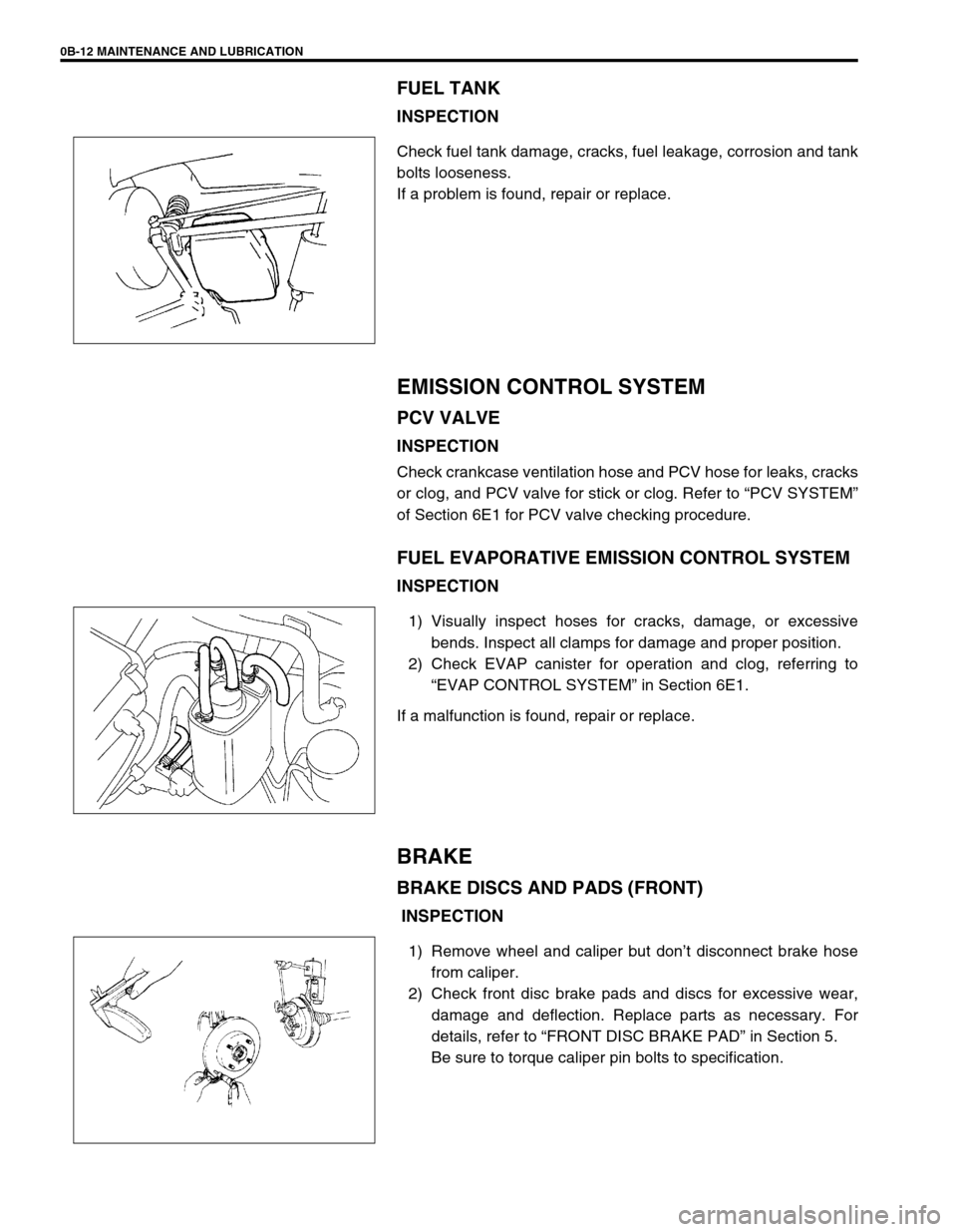
FUEL TANK
INSPECTION
Check fuel tank damage, cracks, fuel leakage, corrosion and tank
bolts looseness.
If a problem is found, repair or replace.
EMISSION CONTROL SYSTEM
PCV VALVE
INSPECTION
Check crankcase ventilation hose and PCV hose for leaks, cracks
or clog, and PCV valve for stick or clog. Refer to “PCV SYSTEM”
of Section 6E1 for PCV valve checking procedure.
FUEL EVAPORATIVE EMISSION CONTROL SYSTEM
INSPECTION
1) Visually inspect hoses for cracks, damage, or excessive
bends. Inspect all clamps for damage and proper position.
2) Check EVAP canister for operation and clog, referring to
“EVAP CONTROL SYSTEM” in Section 6E1.
If a malfunction is found, repair or replace.
BRAKE
BRAKE DISCS AND PADS (FRONT)
INSPECTION
1) Remove wheel and caliper but don’t disconnect brake hose
from caliper.
2) Check front disc brake pads and discs for excessive wear,
damage and deflection. Replace parts as necessary. For
details, refer to “FRONT DISC BRAKE PAD” in Section 5.
Be sure to torque caliper pin bolts to specification.
Page 45 of 698

0B-16 MAINTENANCE AND LUBRICATION
3) Check steering linkage for looseness and damage. Repair or
replace defective parts, if any.
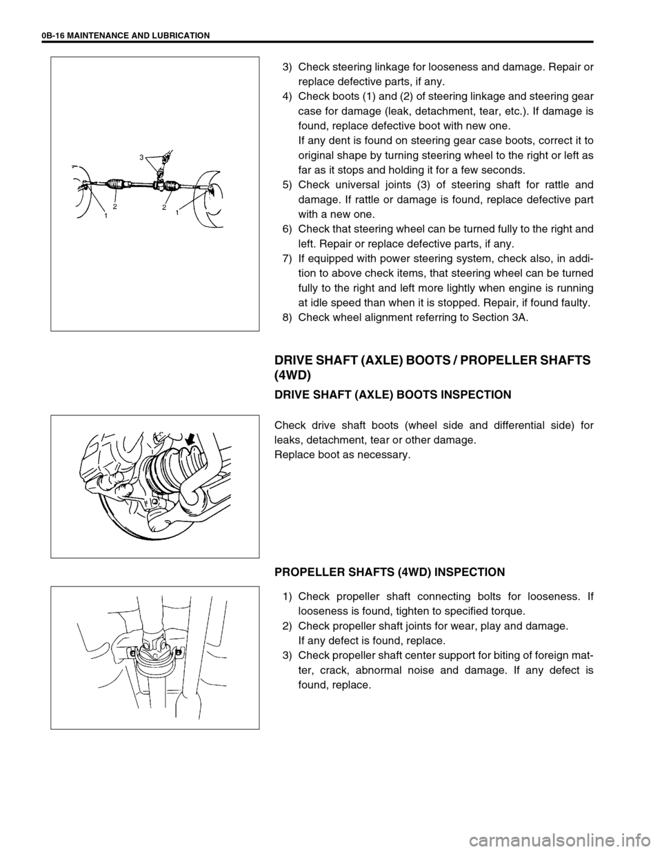
4) Check boots (1) and (2) of steering linkage and steering gear
case for damage (leak, detachment, tear, etc.). If damage is
found, replace defective boot with new one.
If any dent is found on steering gear case boots, correct it to
original shape by turning steering wheel to the right or left as
far as it stops and holding it for a few seconds.
5) Check universal joints (3) of steering shaft for rattle and
damage. If rattle or damage is found, replace defective part
with a new one.
6) Check that steering wheel can be turned fully to the right and
left. Repair or replace defective parts, if any.
7) If equipped with power steering system, check also, in addi-
tion to above check items, that steering wheel can be turned
fully to the right and left more lightly when engine is running
at idle speed than when it is stopped. Repair, if found faulty.
8) Check wheel alignment referring to Section 3A.
DRIVE SHAFT (AXLE) BOOTS / PROPELLER SHAFTS
(4WD)
DRIVE SHAFT (AXLE) BOOTS INSPECTION
Check drive shaft boots (wheel side and differential side) for
leaks, detachment, tear or other damage.
Replace boot as necessary.
PROPELLER SHAFTS (4WD) INSPECTION
1) Check propeller shaft connecting bolts for looseness. If
looseness is found, tighten to specified torque.
2) Check propeller shaft joints for wear, play and damage.
If any defect is found, replace.
3) Check propeller shaft center support for biting of foreign mat-
ter, crack, abnormal noise and damage. If any defect is
found, replace.
Page 112 of 698

STEERING, SUSPENSION, WHEELS AND TIRES 3-3
Hard Steering
Tire not adequately inflated Inflate tires to proper pressure.
Malfunction of power steering system Check and correct.
Bind in tie rod end ball studs or lower ball joints Replace tie rod end or front sus-
pension arm.
Disturbed front end alignment Check and adjust front end align-
ment.
Rack and pinion adjustment Check and adjust rack and pinion
torque.
Bind in steering column Repair or replace.
Too Much Play in
SteeringWheel bearings worn Replace.
Loose steering gear case bolts Tighten.
Rack and pinion adjustments Check and adjust rack and pinion
torque.
Worn steering shaft joints Replace joint.
Worn tie rod ends or tie rod inside ball joints Replace tie rod end or tie rod.
Worn lower ball joints Replace front suspension control
arm.
Poor Returnability
Bind in tie rod end ball studs Replace tie rod end.
Bind in ball joints Replace.
Bind in steering column Repair or replace.
Poorly lubricated rack and pinion Check, repair or lubricate rack and
pinion.
Disturbed front end alignment Check and adjust front end align-
ment.
Rack and pinion adjustment Check and adjust rack and pinion
torque.
Tires not adequately inflated Adjust tire pressure.
Rack and Pinion Noise
(Rattle or Chuckle)Loose steering gear case bolts Tighten.
Worn rack bush Replace.
Rack and pinion adjustment Check and adjust rack and pinion
torque.
Abnormal Noise,
Front EndWorn, sticky or loose tie rod ends, lower ball
joints, tie rod inside ball joints or drive shaft
jointsReplace tie rod end, suspension
arm, tie rod or drive shaft joint.
Damaged struts or mountings Repair or replace.
Worn suspension arm bushings Replace.
Loose stabilizer bar Tighten bolts or nuts, replace
bushes.
Loose wheel nuts Tighten wheel nuts.
Loose suspension bolts or nuts Tighten suspension bolts or nuts.
Broken or otherwise damaged wheel bearings Replace.
Broken suspension springs Replace.
Poorly lubricated or worn strut bearings Replace strut bearing. Condition Possible Cause Correction
Page 113 of 698

3-4 STEERING, SUSPENSION, WHEELS AND TIRES
Wander or Poor
Steering StabilityMismatched or uneven tires Replace or inflate tires to proper
pressure.
Loosen ball joints and tie rod ends Replace suspension arm or tie rod
end.
Faulty struts or mountings Replace strut or repair mounting.
Loose stabilizer bar Tighten or replace stabilizer bar or
bush.
Broken or sagging springs Replace spring.
Rack and pinion adjustment Check and adjust rack and pinion
torque.
Disturbed front end alignment Check and adjust front end align-
ment.
Erratic Steering When
BrakingWorn wheel bearings Replace.
Broken or sagging springs Replace coil spring.
Wheel tires are inflated unequally Inflate tires to proper pressure.
Disturbed front end alignment Check and adjust front end align-
ment.
Brakes not working in unison Check and adjustment brake sys-
tem.
Leaking wheel cylinder or caliper Repair or replace wheel cylinder or
caliper.
Warped discs Replace brake disc.
Badly worn brake linings Replace brake shoe lining.
Drum is out of round in some brakes Replace brake drum.
Defective wheel cylinders Replace or repair wheel cylinder.
Low or Uneven Trim
Height
NOTE:
See NOTE *1.Broken or sagging springs Replace.
Over loaded Check loading.
Incorrect springs Replace.
Ride Too Soft
Faulty struts (shock absorber) Replace strut.
Suspension Bottoms
Overloaded Check loading.
Faulty struts (shock absorber) Replace strut.
Incorrect, broken or sagging springs Replace.
Body Leans or Sways
in CornersLoose stabilizer bar Tighten stabilizer bar bolts or nuts,
or replace bushes.
Faulty struts (shock absorbers) or mountings Replace strut or tighten mounting.
Broken or sagging springs Replace.
Overloaded Check loading.
Cupped Tires
Front struts defective Replace.
Worn wheel bearings Replace.
Excessive tire or wheel run-out Replace tire or wheel disc.
Worn ball joints Replace front suspension arm.
Tire out of balance Adjust tire balance. Condition Possible Cause Correction
Page 128 of 698

MANUAL RACK AND PINION 3B-7
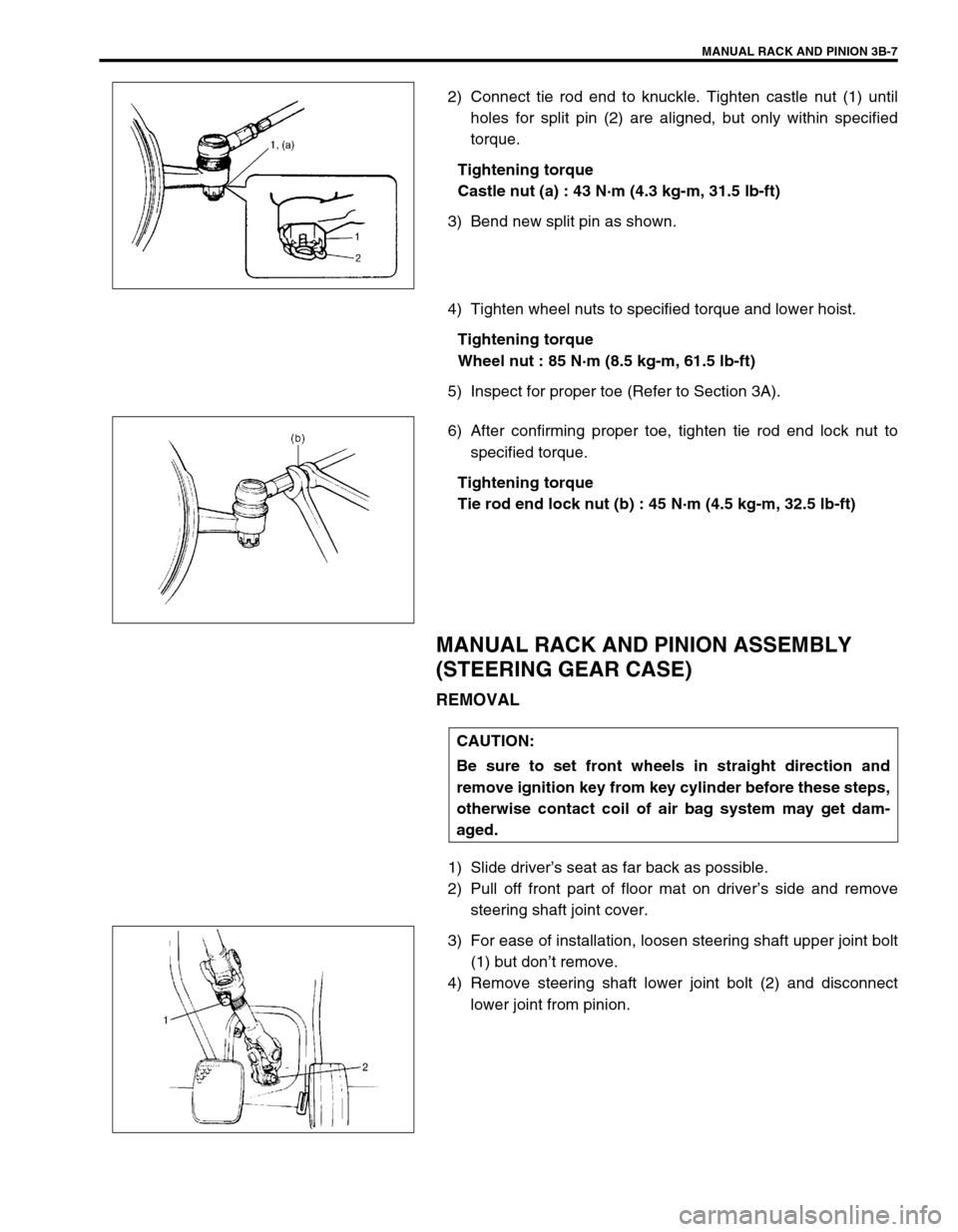
2) Connect tie rod end to knuckle. Tighten castle nut (1) until
holes for split pin (2) are aligned, but only within specified
torque.
Tightening torque
Castle nut (a) : 43 N·m (4.3 kg-m, 31.5 lb-ft)
3) Bend new split pin as shown.
4) Tighten wheel nuts to specified torque and lower hoist.
Tightening torque
Wheel nut : 85 N·m (8.5 kg-m, 61.5 lb-ft)
5) Inspect for proper toe (Refer to Section 3A).
6) After confirming proper toe, tighten tie rod end lock nut to
specified torque.
Tightening torque
Tie rod end lock nut (b) : 45 N·m (4.5 kg-m, 32.5 lb-ft)
MANUAL RACK AND PINION ASSEMBLY
(STEERING GEAR CASE)
REMOVAL
1) Slide driver’s seat as far back as possible.
2) Pull off front part of floor mat on driver’s side and remove
steering shaft joint cover.
3) For ease of installation, loosen steering shaft upper joint bolt
(1) but don’t remove.
4) Remove steering shaft lower joint bolt (2) and disconnect
lower joint from pinion.
CAUTION:
Be sure to set front wheels in straight direction and
remove ignition key from key cylinder before these steps,
otherwise contact coil of air bag system may get dam-
aged.
Page 130 of 698

MANUAL RACK AND PINION 3B-9
INSTALLATION
1) Mount steering gear case (2) to body and tighten gear case
mount bolts (1) to specified torque.
Tightening torque
Gear case mount bolt (a) : 25 N·m (2.5 kg-m, 18.0 lb-ft)
2) Install exhaust No.1 pipe (3).
3) Install both tie rod ends (1) to knuckles (2). Tighten each
castle nut (3) until holes for split pin (4) align but within spec-
ified torque and then bend new split pin as shown.
Tightening torque
Castle nut (b) : 43 N·m (4.3 kg-m, 31.5 lb-ft)
4) Be sure that steering wheel and both brake discs are all
straight ahead driving state and then insert steering lower
joint into steering pinion shaft.
5) Tighten steering shaft joint bolts to specified torque (Lower
side (2) first and then upper side (1)).
Tightening torque
Steering shaft joint bolt (c) : 25 N·m (2.5 kg-m, 18.0 lb-ft)2
1, (a)
1
Page 175 of 698

3C-2 STEERING WHEEL AND COLUMN
GENERAL DESCRIPTION
STEERING COLUMN
This double tube type steering column has following three important features in addition to the steering function
:
The column is energy absorbing, designed to compress in a front-end collision.
The ignition switch and lock are mounted conveniently on this column.
With the column mounted lock, the ignition and steering operations can be locked to inhibit theft of the vehi-
cle.
To insure the energy absorbing action, it is important that only the specified screws, bolts, and nuts be used as
designated and that they are tightened to the specified torque.
When the column assembly is removed from the vehicle, special care must be taken in handling it. Use of a
steering wheel puller other than the one recommended in this manual or a sharp blow on the end of the steering
shaft, leaning on the assembly, or dropping the assembly could shear the plastic shear pins which maintain col-
umn length and position.
STEERING WHEEL AND DRIVER AIR BAG (INFLATOR) MODULE
The driver air bag (inflator) module is one of the supplemental restraint (air bag) system components and is
mounted to the center of the steering wheel. During certain frontal crashes, the air bag system supplements the
restraint of the driver’s and passenger’s seat belts by deploying the air bags.
The air bag (inflator) module should be handled with care to prevent accidental deployment. When servicing, be
sure to observe all WARNINGS and CAUTIONS and “SERVICE PRECAUTIONS” under “ON-VEHICLE SER-
VICE” in Section 10B.
DIAGNOSIS
For maintenance service of the steering wheel and column, refer to Section 0B.
For diagnosis of the steering wheel and column, refer to Section 3.
For diagnosis of the air bag system, refer to Section 10B.
INSPECTION AND REPAIR REQUIRED AFTER ACCIDENT
After an accident, whether the air bag has been deployed or not, be sure to perform checks, inspections and
repairs described under “CHECKING STEERING COLUMN ASSEMBLY AND LOWER SHAFT FOR ACCI-
DENT DAMAGE” as well as “REPAIRS AND INSPECTIONS REQUIRED AFTER ACCIDENT” under “DIAGNO-
SIS” in Section 10B.
Page 176 of 698

STEERING WHEEL AND COLUMN 3C-3
ON-VEHICLE SERVICE
SERVICE PRECAUTIONS
For service precautions, refer to “SERVICE PRECAUTIONS” under “ON-VEHICLE SERVICE” in Section 10B.
SERVICE AND DIAGNOSIS
For diagnosis and servicing, refer to “SERVICE AND DIAGNOSIS” under “SERVICE PRECAUTIONS” in Sec-
tion 10B.
DISABLING AIR BAG SYSTEM
For disabling air bag system, refer to “DISABLING AIR BAG SYSTEM” under “SERVICE PRECAUTIONS” in
Section 10B.
ENABLING AIR BAG SYSTEM
For enabling air bag system, refer to “ENABLING AIR BAG SYSTEM” under “SERVICE PRECAUTIONS” in
Section 10B.
1. Driver air bag (inflator) module 7. Steering column assembly 13. Immobilizer control module (if equipped)
2. Steering wheel 8. Steering lock assembly (ignition switch) 14. Upper and lower joint bolt
: After tightening lower joint bolt, tighten upper joint bolt.
3. Steering wheel nut 9. P/S control module (if equipped) 15. Steering column mounting nut
: After tightening lower nut, tightening upper nut.
4. Contact coil and combination
switch assembly10. Motor for P/S system (if equipped) Tightening torque
5. Steering column upper cover 11. Steering lower shaft
6. Steering column lower cover 12. Steering joint cover