Page 147 of 698

3B1-6 ELECTRICAL POWER STEERING (P/S) SYSTEM
For identify current DTC, clear history DTC referring to “DTC CLEARANCE” in this section. NOTE:
As execution of “DTC CLEARANCE” will clear all malfunction DTCs, be sure to record all DTCs
before servicing.
When 2 or more codes are indicated, the lowest numbered code will appear first.
If a code not listed on “DTC TABLE” is displayed, then the P/S control module is faulty.
DTC C1122 or DTC No.22 (flashing pattern : 22) is indicated when ignition switch is ON and engine
is not running but if DTC No.12 (flashing pattern : 12) is indicated when engine is started, it means
nothing abnormal.
Current DTC and history DTC can be identified by lighting and flashing of “EPS” warning lamp.
“EPS” warning lamp operates as follow depending on the trouble condition.
Current DTC is set.
(Abnormality exists at
present.)History DTC is set only.
(Faulty condition occurred
once in the past but normal
condition is restored at
present.)Current DTC and history
DTC exist.
“EPS” warning lamp after
engine startedRemains ON. Turn OFF. Remains ON.
“EPS” warning lamp when
shorting diagnosis switch ter-
minal and ground terminalDisplays current DTC. Displays history DTC.Displays current DTC and
history DTC.
Page 149 of 698

3B1-8 ELECTRICAL POWER STEERING (P/S) SYSTEM
DTC CHECK
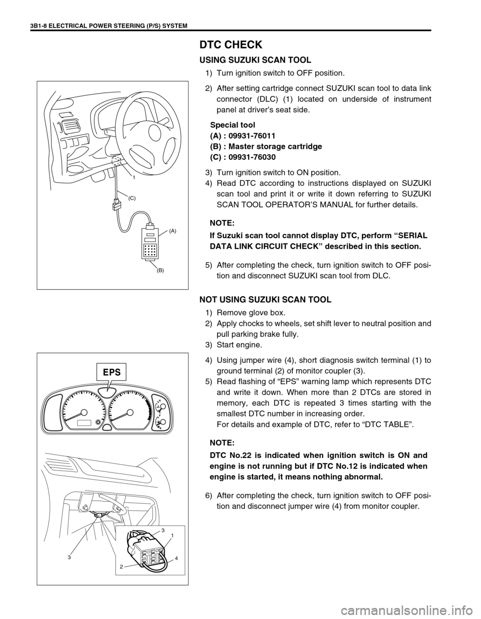
USING SUZUKI SCAN TOOL
1) Turn ignition switch to OFF position.
2) After setting cartridge connect SUZUKI scan tool to data link
connector (DLC) (1) located on underside of instrument
panel at driver’s seat side.
Special tool
(A) : 09931-76011
(B) : Master storage cartridge
(C) : 09931-76030
3) Turn ignition switch to ON position.
4) Read DTC according to instructions displayed on SUZUKI
scan tool and print it or write it down referring to SUZUKI
SCAN TOOL OPERATOR’S MANUAL for further details.
5) After completing the check, turn ignition switch to OFF posi-
tion and disconnect SUZUKI scan tool from DLC.
NOT USING SUZUKI SCAN TOOL
1) Remove glove box.
2) Apply chocks to wheels, set shift lever to neutral position and
pull parking brake fully.
3) Start engine.
4) Using jumper wire (4), short diagnosis switch terminal (1) to
ground terminal (2) of monitor coupler (3).
5) Read flashing of “EPS” warning lamp which represents DTC
and write it down. When more than 2 DTCs are stored in
memory, each DTC is repeated 3 times starting with the
smallest DTC number in increasing order.
For details and example of DTC, refer to “DTC TABLE”.
6) After completing the check, turn ignition switch to OFF posi-
tion and disconnect jumper wire (4) from monitor coupler. NOTE:
If Suzuki scan tool cannot display DTC, perform “SERIAL
DATA LINK CIRCUIT CHECK” described in this section.
(B)(A) (C)1
NOTE:
DTC No.22 is indicated when ignition switch is ON and
engine is not running but if DTC No.12 is indicated when
engine is started, it means nothing abnormal.
3
21
3
4
Page 150 of 698

ELECTRICAL POWER STEERING (P/S) SYSTEM 3B1-9
DTC CLEARANCE
USING SUZUKI SCAN TOOL
1) Turn ignition switch to OFF position.
2) After setting cartridge connect SUZUKI scan tool, connect
scan tool to data link connector (DLC) (1) located on under-
side of instrument panel at driver’s seat side.
Special tool
(A) : 09931-76011
(B) : Master storage cartridge
(C) : 09931-76030
3) Turn ignition switch to ON position.
4) Erase DTC according to instructions displayed on SUZUKI
scan tool referring to “SUZUKI SCAN TOOL OPERATOR’S
MANUAL” for further details.
5) After completing the check, turn ignition switch to OFF posi-
tion and disconnect SUZUKI scan tool from DLC.
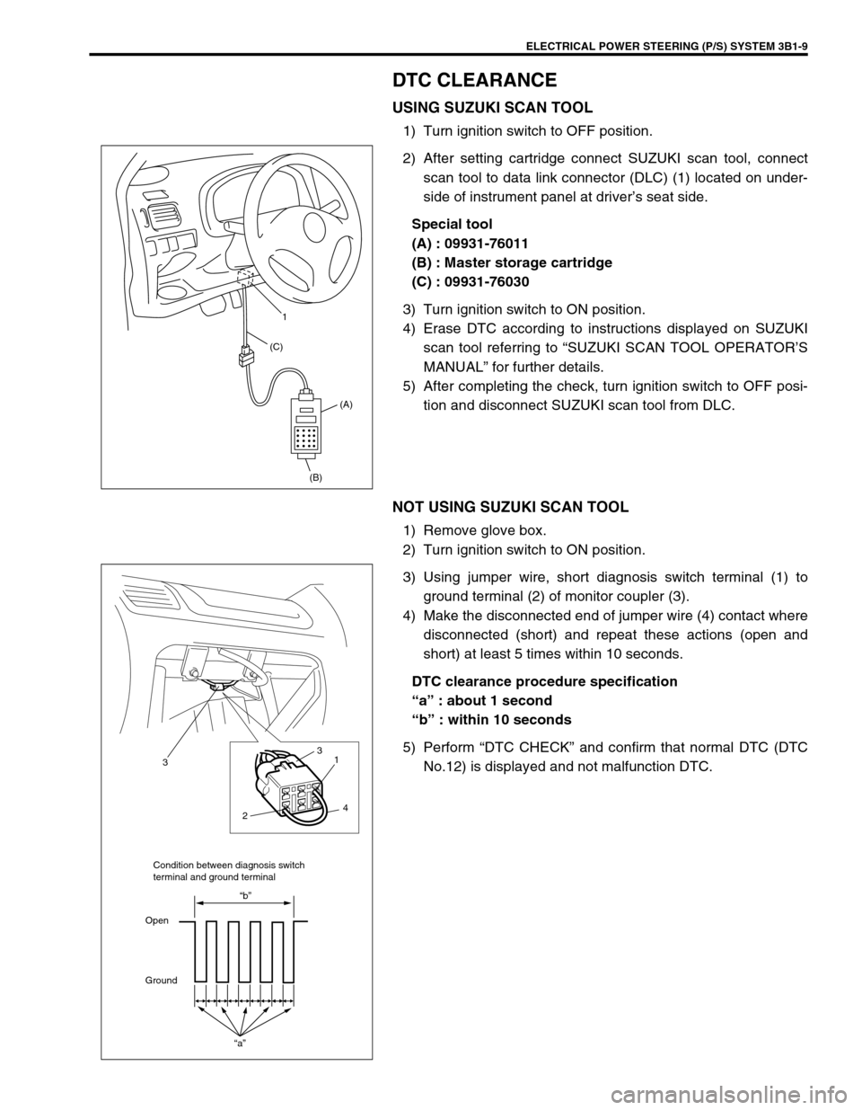
NOT USING SUZUKI SCAN TOOL
1) Remove glove box.
2) Turn ignition switch to ON position.
3) Using jumper wire, short diagnosis switch terminal (1) to
ground terminal (2) of monitor coupler (3).
4) Make the disconnected end of jumper wire (4) contact where
disconnected (short) and repeat these actions (open and
short) at least 5 times within 10 seconds.
DTC clearance procedure specification
“a” : about 1 second
“b” : within 10 seconds
5) Perform “DTC CHECK” and confirm that normal DTC (DTC
No.12) is displayed and not malfunction DTC.
(B)(A) (C)1
21
3
3
4
“a”
“b”
Open
GroundCondition between diagnosis switch
terminal and ground terminal
Page 153 of 698
3B1-12 ELECTRICAL POWER STEERING (P/S) SYSTEM
DTC (displayed
on SUZUKI scan
tool)“EPS” light flashing pattern
DTC (indicated
by “EPS” light
flashing pattern)Model DIAGNOSTIC ITEM DIAGNOSIS
NO DTC 12 NormalThis code appears
when none of the other
codes are identified.
C1111 11
Torque sensor
Diagnose trouble
according to “DIAG-
NOSTIC FLOW
TABLE” corresponding
to each code No. C1113 13
C1114 14
C1115 15
C1116 16
C1121 21
VSS signal C1123 23
C1124 24
C1122 22Engine speed sig-
nal
C1141 41
Motor C1142 42
C1143 43
C1144 44
C1145 45
C1151 51 Clutch
C1152 52
P/S control module C1154 54
C1155 55
C1153 53P/S control module
power supply
Page 336 of 698

ANTILOCK BRAKE SYSTEM (ABS) 5E-11
c) Diagnostic Trouble Code (DTC) Check, Record and Clearance
Perform “DIAGNOSTIC TROUBLE CODE CHECK” procedure in this section, record it and then clear it
referring to “DIAGNOSTIC TROUBLE CODE CLEARANCE” in this section.
If the malfunction DTC which was once displayed and then cleared cannot be detected (indicated) again
when the ignition switch is turned ON, attempt to diagnose the trouble based on the DTC recorded in this
step may mislead the diagnosis or make diagnosing difficult. Proceed to Step 2) to check control module
for proper self-diagnosis function.
If the malfunction DTC which was once displayed and then cleared can be detected (indicated) again when
ignition switch is turned ON, proceed to Step 3).
2) DRIVING TEST
Test drive the vehicle at 40 km/h for more than a minute and check if any trouble symptom (such as abnor-
mal lighting of ABS warning light) exists.
If the malfunction DTC is confirmed again at ignition switch ON, driving test as described in above is not nec-
essary. Proceed to Step 3).
3) DIAGNOSTIC TROUBLE CODE CHECK
Recheck diagnostic trouble code referring to “DTC CHECK” as shown in the following page.
4) DIAGNOSTIC TROUBLE CODE FLOW TABLE
According to Diagnostic flow table for the diagnostic trouble code confirmation in Step 3), locate the cause of
the trouble, namely in a sensor, switch, wire harness, connector, actuator assembly or other part and repair
or replace faulty parts.
5)“DIAGNOSIS” IN “BRAKES” SECTION
Check the parts or system suspected as a possible cause referring to “DIAGNOSIS” in “BRAKES” section
and based on symptoms appearing on the vehicle (symptom obtained through Steps 1)-a, 1)-b and 2) and
repair or replace faulty parts, if any).
6) CHECK FOR INTERMITTENT PROBLEM
Check parts where an intermittent trouble is easy to occur (e.g., wire harness, connector, etc.), referring to
“INTERMITTENT TROUBLE” in “GENERAL INFORMATION” section and related circuit of trouble code
recorded in Step 1)-c.
7) FINAL CONFIRMATION TEST
Confirm that the problem symptom has gone and the ABS is free from any abnormal conditions. If what has
been repaired is related to the malfunction DTC, clear the DTC once and perform test driving and confirm
that no DTC is indicated.
Page 344 of 698

ANTILOCK BRAKE SYSTEM (ABS) 5E-19
DIAGNOSTIC TROUBLE CODE (DTC) CHECK
(USING SUZUKI SCAN TOOL)
1) After setting cartridge for ABS to SUZUKI scan tool, connect
SUZUKI scan tool to data link connector.
Special tool
(A) : 09931-76011 (SUZUKI scan tool)
(B) : Mass storage cartridge
(C) : 09931-76030 (16/14 pin DLC cable)
2) Turn ignition switch ON.
3) Read DTC according to instructions displayed on SUZUKI
scan tool and print it or write it down. Refer to SUZUKI scan
tool operator’s manual for further details.
4) After completing the check, turn ignition switch off and dis-
connect SUZUKI scan tool from DLC.
DIAGNOSTIC TROUBLE CODE (DTC) CLEAR-
ANCE
After repair or replace malfunction part(s), clear all DTCs by per-
forming the following procedure.
1) Turn ignition switch OFF.
2) Using service wire (4), connect diagnosis switch terminal (2)
of diagnosis monitor coupler (1) to ground terminal (3).
3) With connection described in above Step 2) maintained, turn
ignition switch ON.
(A)
(B) (C)
WARNING:
When performing a driving test, select a safe place where
there is neither any traffic nor any traffic accident possi-
bility and be very careful during testing to avoid occur-
rence of an accident.
3 11
2
4
Page 345 of 698
5E-20 ANTILOCK BRAKE SYSTEM (ABS)
4) Repeat disconnecting and reconnecting of service wire
between diagnosis and ground terminals 5 times or more at
about 1sec. interval within 10 seconds.
5) Turn ignition switch OFF and disconnect service wire from
monitor coupler.
6) Perform “DRIVING TEST” (Step 2 of “ABS DIAGNOSTIC
FLOW TABLE” in this section) and “DTC CHECK” and con-
firm that normal DTC (DTC 12) is displayed ; not malfunction
DTC.
DIAGNOSTIC TROUBLE CODE (DTC) TABLE
O : Open
S : Short
T : About 10 seconds
NOTE:
It is also possible to clear DTC by using SUZUKI scan
tool. Refer to Cartridge Manual for procedure to clear
DTC.
CAUTION:
Be sure to perform “ABS DIAGNOSTIC FLOW TABLE” before starting diagnosis.
DTC
(displayed
on SUZUKI
scan tool)DTC
(indicated by
ABS warning
lamp)ABS warning lamp flashing
patternDIAGNOSTIC ITEMS
NO DTC 12 Normal
C1013 13 ABS control module
C1015 15 G sensor circuit
C1021 21 RF
Wheel speed sensor circuit C1025 25 LF
C1031 31 RR
C1035 35 LR
Page 346 of 698
ANTILOCK BRAKE SYSTEM (ABS) 5E-21
C1022 22 RF
Wheel speed sensor circuit
or sensor ring C1026 26 LF
C1032 32 RR
C1036 36 LR
C1041 41
RFInlet solenoid valve circuit
C1042 42 Outlet solenoid valve circuit
C1045 45
LFInlet solenoid valve circuit
C1046 46 Outlet solenoid valve circuit
C1051 51
RRInlet solenoid valve circuit
C1052 52 Outlet solenoid valve circuit
C1055 55
LRInlet solenoid valve circuit
C1056 56 Outlet solenoid valve circuit
C1057 57 Power source
C1061 61 ABS pump motor and/or motor relay circuit
C1063 63 Fail safe-relay
C1071 71 ABS control moduleDTC
(displayed
on SUZUKI
scan tool)DTC
(indicated by
ABS warning
lamp)ABS warning lamp flashing
patternDIAGNOSTIC ITEMS