Page 265 of 698
4A-12 FRONT DRIVE SHAFT
7) Driver in the cage (1) by using a pipe (2).
Drive shaft joint cage installing pipe diameter
“a” : 22.5 mm (0.886 in.) or more
“b” : 30.0 mm (1.181 in.) or less
8) Install circlip (1) by using special tool (A).
Special tool
(A) : 09900-06107
9) Apply grease to entire surface of cage.
Use specified grease in tube included in spare parts.
10) Insert cage into outer race and fit snap ring (1) into groove of
outer race (2).
11) Apply grease to inside of outer race, and fit boot to outer
race. After fitting boot, insert screwdriver into boot on outer
race side and allow air to enter boot so that air pressure in
boot becomes the same as atmospheric pressure. CAUTION:
Install cage directing smaller outside diameter side to
wheel side.
CAUTION:
Position opening of snap ring “c” so that it will not be
lined up with a ball.
Page 285 of 698
5-12 BRAKES
2) Start engine while depressing brake pedal. If pedal travel
increases a little, operation is satisfactory. But no change in
pedal travel indicates malfunction.
CHECK AIR TIGHTNESS UNDER LOAD
1) With engine running, depress brake pedal. Then stop engine
while holding brake pedal depressed.
2) Hold brake pedal depressed for 30 seconds. If pedal height
does not change, condition is good. But it isn’t if pedal rises.
FLUID PRESSURE TEST (IF EQUIPPED WITH
LSPV)
Test procedure for LSPV assembly is as follows.
Before testing, confirm the following.
Fuel tank is filled with fuel fully.
Vehicle is equipped with spare tire, tools, jack and jack han-
dle.
H: Hold
H: Hold
T: 30 seconds
Page 322 of 698

BRAKES 5-49
INSTALLATION
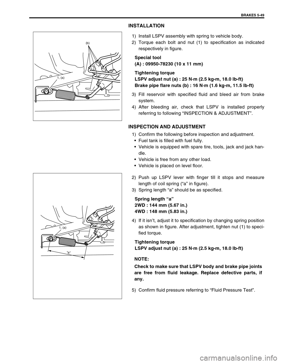
1) Install LSPV assembly with spring to vehicle body.
2) Torque each bolt and nut (1) to specification as indicated
respectively in figure.
Special tool
(A) : 09950-78230 (10 x 11 mm)
Tightening torque
LSPV adjust nut (a) : 25 N·m (2.5 kg-m, 18.0 lb-ft)
Brake pipe flare nuts (b) : 16 N·m (1.6 kg-m, 11.5 lb-ft)
3) Fill reservoir with specified fluid and bleed air from brake
system.
4) After bleeding air, check that LSPV is installed properly
referring to following “INSPECTION & ADJUSTMENT”.
INSPECTION AND ADJUSTMENT
1) Confirm the following before inspection and adjustment.
Fuel tank is filled with fuel fully.
Vehicle is equipped with spare tire, tools, jack and jack han-
dle.
Vehicle is free from any other load.
Vehicle is placed on level floor.
2) Push up LSPV lever with finger till it stops and measure
length of coil spring (“a” in figure).
3) Spring length “a” should be as specified.
Spring length “a”
2WD : 144 mm (5.67 in.)
4WD : 148 mm (5.83 in.)
4) If it isn’t, adjust it to specification by changing spring position
as shown in figure. After adjustment, tighten nut (1) to speci-
fied torque.
Tightening torque
LSPV adjust nut (a) : 25 N·m (2.5 kg-m, 18.0 lb-ft)
5) Confirm fluid pressure referring to “Fluid Pressure Test”.
1, (a)
(b)
NOTE:
Check to make sure that LSPV body and brake pipe joints
are free from fluid leakage. Replace defective parts, if
any.
1, (a)
“a”