2000 SUZUKI SWIFT instrument panel
[x] Cancel search: instrument panelPage 1 of 698

IMPORTANT
WARNING/CAUTION/NOTE
Please read this manual and follow its instructions carefully. To emphasize special information, the words
WARNING, CAUTION
and NOTE
have special meanings. Pay special attention to the messages highlighted by
these signal words.
WARNING:
Indicates a potential hazard that could result in death or injury.
CAUTION:
Indicates a potential hazard that could result in vehicle damage.
NOTE:
Indicates special information to make maintenance easier or instructions clearer.
WARNING:
This service manual is intended for authorized Suzuki dealers and qualified service mechanics only.
Inexperienced mechanics or mechanics without the proper tools and equipment may not be able to
properly perform the services described in this manual.
Improper repair may result in injury to the mechanic and may render the vehicle unsafe for the driver
and passengers.
WARNING:
For vehicles equipped with a Supplemental Restraint (Air Bag) System:
• Service on and around the air bag system components or wiring must be performed only by an
authorized SUZUKI dealer. Refer to “Air Bag System Components and Wiring Location View” under
“General Description” in air bag system section in order to confirm whether you are performing ser-
vice on or near the air bag system components or wiring. Please observe all WARNINGS and “Ser-
vice Precautions” under “On-Vehicle Service” in air bag system section before performing service
on or around the air bag system components or wiring. Failure to follow WARNINGS could result in
unintentional activation of the system or could render the system inoperative. Either of these two
conditions may result in severe injury.
If the air bag system and another vehicle system both need repair, Suzuki recommends that the air
bag system be repaired first, to help avoid unintended air bag system activation.
Do not modify the steering wheel, instrument panel or any other air bag system component (on or
around air bag system components or wiring). Modifications can adversely affect air bag system
performance and lead to injury.
If the vehicle will be exposed to temperatures over 93°C (200°F) (for example, during a paint baking
process), remove the air bag system components (air bag (inflator) modules, SDM and/or seat belt
with pretensioner) beforehand to avoid component damage or unintended activation.
Page 57 of 698

1A-6 HEATER AND VENTILATION
REMOVAL
1) Disconnect negative (–) cable at battery.
2) Drain engine coolant and disconnect heater hoses (1) from
heater unit.
3) Remove heater unit mounting nut (2).
4) Remove instrument panel by referring to “INSTRUMENT
PANEL” in Section 9.
5) Disconnect blower motor and resistor couplers from heater
unit.
6) Remove bolts (1), nuts (2) and screws (3) as shown.
7) Remove cooling unit (4) and heater unit (5) from vehicle.
INSTALLATION
Reverse removal procedure to install heater unit noting the follow-
ing instructions.
When installing each part, be careful not to catch any cable
or wiring harness.
Adjust heater control cable by referring to “HEATER CON-
TROL LEVER ASSEMBLY” in this section.
Fill engine coolant to radiator.
Page 149 of 698

3B1-8 ELECTRICAL POWER STEERING (P/S) SYSTEM
DTC CHECK
USING SUZUKI SCAN TOOL
1) Turn ignition switch to OFF position.
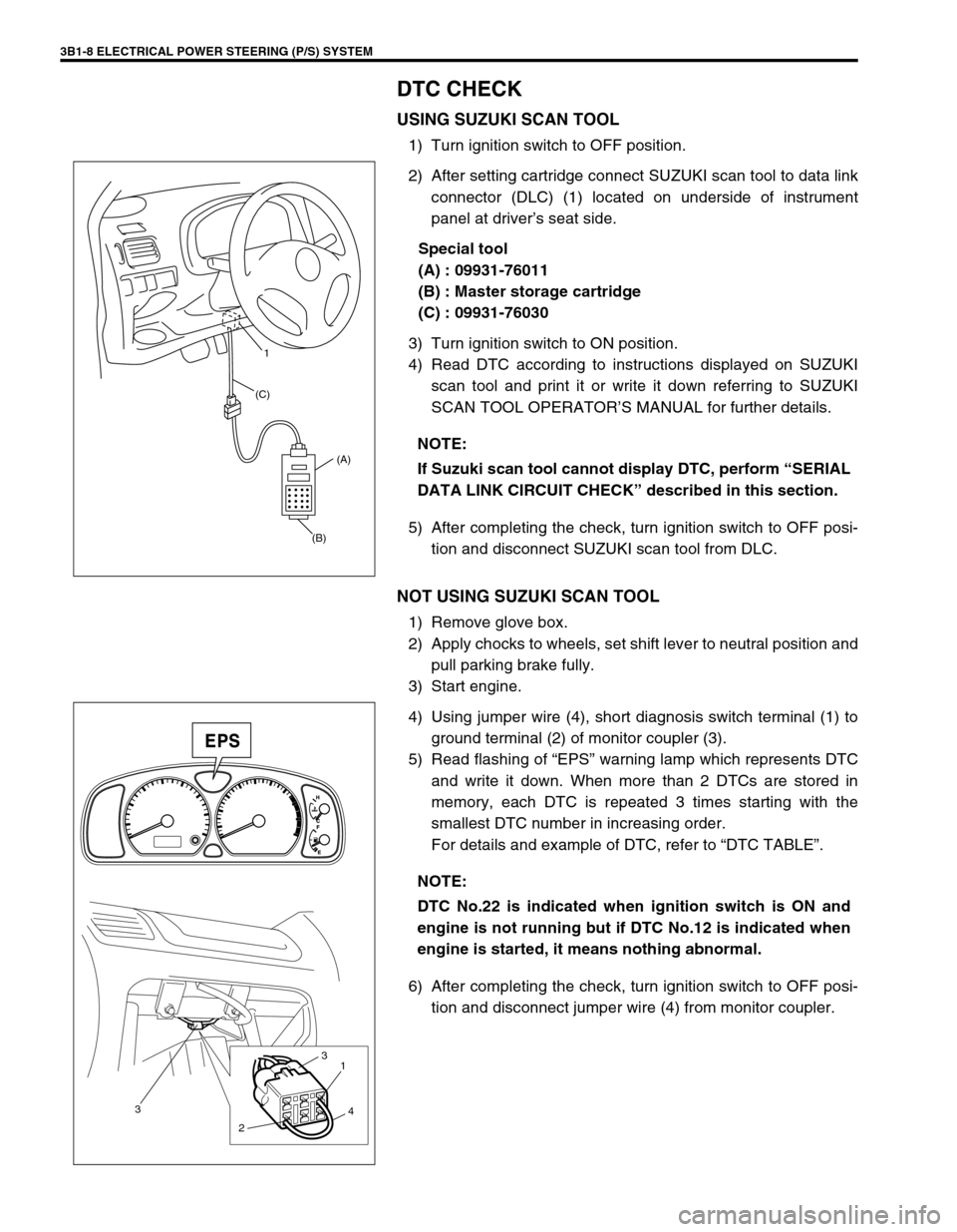
2) After setting cartridge connect SUZUKI scan tool to data link
connector (DLC) (1) located on underside of instrument
panel at driver’s seat side.
Special tool
(A) : 09931-76011
(B) : Master storage cartridge
(C) : 09931-76030
3) Turn ignition switch to ON position.
4) Read DTC according to instructions displayed on SUZUKI
scan tool and print it or write it down referring to SUZUKI
SCAN TOOL OPERATOR’S MANUAL for further details.
5) After completing the check, turn ignition switch to OFF posi-
tion and disconnect SUZUKI scan tool from DLC.
NOT USING SUZUKI SCAN TOOL
1) Remove glove box.
2) Apply chocks to wheels, set shift lever to neutral position and
pull parking brake fully.
3) Start engine.
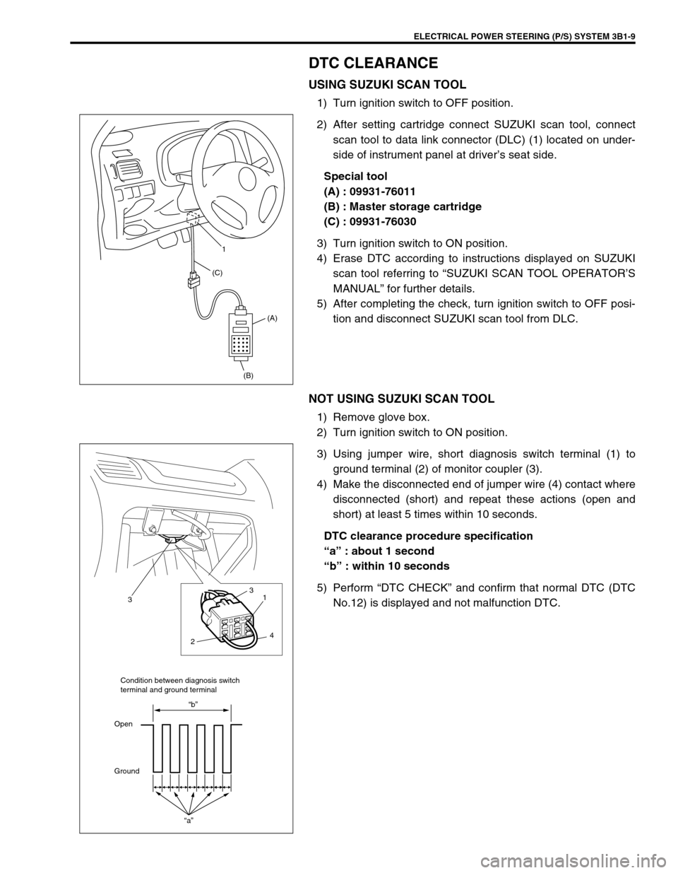
4) Using jumper wire (4), short diagnosis switch terminal (1) to
ground terminal (2) of monitor coupler (3).
5) Read flashing of “EPS” warning lamp which represents DTC
and write it down. When more than 2 DTCs are stored in
memory, each DTC is repeated 3 times starting with the
smallest DTC number in increasing order.
For details and example of DTC, refer to “DTC TABLE”.
6) After completing the check, turn ignition switch to OFF posi-
tion and disconnect jumper wire (4) from monitor coupler. NOTE:
If Suzuki scan tool cannot display DTC, perform “SERIAL
DATA LINK CIRCUIT CHECK” described in this section.
(B)(A) (C)1
NOTE:
DTC No.22 is indicated when ignition switch is ON and
engine is not running but if DTC No.12 is indicated when
engine is started, it means nothing abnormal.
3
21
3
4
Page 150 of 698

ELECTRICAL POWER STEERING (P/S) SYSTEM 3B1-9
DTC CLEARANCE
USING SUZUKI SCAN TOOL
1) Turn ignition switch to OFF position.
2) After setting cartridge connect SUZUKI scan tool, connect
scan tool to data link connector (DLC) (1) located on under-
side of instrument panel at driver’s seat side.
Special tool
(A) : 09931-76011
(B) : Master storage cartridge
(C) : 09931-76030
3) Turn ignition switch to ON position.
4) Erase DTC according to instructions displayed on SUZUKI
scan tool referring to “SUZUKI SCAN TOOL OPERATOR’S
MANUAL” for further details.
5) After completing the check, turn ignition switch to OFF posi-
tion and disconnect SUZUKI scan tool from DLC.
NOT USING SUZUKI SCAN TOOL
1) Remove glove box.
2) Turn ignition switch to ON position.
3) Using jumper wire, short diagnosis switch terminal (1) to
ground terminal (2) of monitor coupler (3).
4) Make the disconnected end of jumper wire (4) contact where
disconnected (short) and repeat these actions (open and
short) at least 5 times within 10 seconds.
DTC clearance procedure specification
“a” : about 1 second
“b” : within 10 seconds
5) Perform “DTC CHECK” and confirm that normal DTC (DTC
No.12) is displayed and not malfunction DTC.
(B)(A) (C)1
21
3
3
4
“a”
“b”
Open
GroundCondition between diagnosis switch
terminal and ground terminal
Page 182 of 698

STEERING WHEEL AND COLUMN 3C-9
5) Remove contact coil and combination switch assembly
screws (1) and disconnect connectors (2) from combination
switch (3).
6) Disconnect horn connector (1) from instrument panel har-
ness.
7) Remove contact coil and combination switch assembly from
steering column.
INSPECTION
Check contact coil harness (1) for any signs of scorching, melting
or other damage.
If it is damaged, replace.
INSTALLATION
1) Check to make sure that vehicle’s front tires are set at
straight-ahead position and then ignition switch is at “LOCK”
position.
2) Connect all connectors disconnected in REMOVAL.
Page 183 of 698

3C-10 STEERING WHEEL AND COLUMN
3) Install contact coil and combination switch assembly (3) to
steering column.
4) Install steering column upper cover (2) and lower cover (3),
and then tighten steering column cover screws (1).
5) Install steering column hole cover (1).
6) Install steering wheel to steering column. Refer to “STEER-
ING WHEEL”.
STEERING COLUMN ASSEMBLY
NOTE:
New contact coil and combination switch assembly is
supplied with contact coil set and held at its center posi-
tion with a lock pin (1) and seal (2). Remove this lock pin
after installing contact coil and combination switch
assembly to steering column.
CAUTION:
When installing lower cover (3) and upper cover (2), be
careful so that contact coil and combination switch lead
wire is not caught between covers.
1
CAUTION:
Once the steering column is removed from the vehicle,
the column is extremely susceptible to damage.
Dropping the column assembly on its end could col-
lapse the steering shaft or loosen the plastic shear
pins which maintain column length.
Leaning on the column assembly could cause it to
bend or deform.
Any of the above damage could impair the column’s col-
lapsible design.
NOTE:
When servicing steering column or any column-mounted
component, remove steering wheel. But when removing
steering column simply to gain access to instrument
panel components, leave steering wheel installed on
steering column.
Page 186 of 698

STEERING WHEEL AND COLUMN 3C-13
11) Disconnect horn connector (1) from instrument panel har-
ness.
12) If equipped with power steering (P/S) system, disconnect
connector (2) from P/S control module (1).
13) Remove steering joint cover.
14) Make alignment marks (1) on joint (2) of steering column and
steering lower shaft (3) for a guide during reinstallation.
15) Remove joint bolt (steering column side) (4).
16) Remove steering column mounting nuts (“A”, “B”).
17) Remove steering column assembly from vehicle.
18) If it is necessary to remove steering lock assembly (ignition
switch), remove it, referring to “STEERING LOCK ASSEM-
BLY (IGNITION SWITCH)” in this section.
CAUTION:
Don’t separate steering column assembly into steering
column and shaft. If column or shaft is defective, replace
as an assembly.
Page 376 of 698

ENGINE GENERAL INFORMATION AND DIAGNOSIS 6-7
ON-BOARD DIAGNOSTIC SYSTEM (VEHICLE
WITH IMMOBILIZER INDICATOR LAMP)
ECM in this vehicle has following functions.
When the ignition switch is turned ON with the engine at a
stop, malfunction indicator lamp (MIL) (1) turns ON to check
the bulb of the malfunction indicator lamp (1).
When ECM detects a malfunction which gives an adverse
effect to vehicle emission while the engine is running, it
makes the malfunction indicator lamp (1) in the meter cluster
of the instrument panel turn ON or flash (flashing only when
detecting a misfire which can cause damage to the catalyst)
and stores the malfunction area in its memory.
(If it detects that continuously 3 driving cycles are normal
after detecting a malfunction, however, it makes MIL (1) turn
OFF although DTC stored in its memory will remain.)
As a condition for detecting a malfunction in some areas in
the system being monitored by ECM and turning ON the
malfunction indicator lamp (1) due to that malfunction, 2 driv-
ing cycle detection logic is adopted to prevent erroneous
detection.
When a malfunction is detected, engine and driving condi-
tions then are stored in ECM memory as freeze frame data.
(For the details, refer to description on Freeze frame data.)
It is possible to communicate by using not only SUZUKI scan
tool (Tech-1) (2) but also generic scan tool. (Diagnostic infor-
mation can be accessed by using a scan tool.)
WARM-UP CYCLE
A warm-up cycle means sufficient vehicle operation such that the
coolant temperature has risen by at least 22°C (40°F) from
engine starting and reaches a minimum temperature of 70°C
(160°F).
DRIVING CYCLE
A “Driving Cycle” consists of engine startup, driving mode where
a malfunction would be detected if present, and engine shutoff.
2 DRIVING CYCLES DETECTION LOGIC
The malfunction detected in the first driving cycle is stored in
ECM memory (in the form of pending DTC and freeze frame data)
but the malfunction indicator lamp does not light at this time. It
lights up at the second detection of same malfunction also in the
next driving cycle.
PENDING DTC
Pending DTC means a DTC detected and stored temporarily at
the first driving cycle of the DTC which is detected in the 2 driving
cycle detection logic.
3. Immobilizer indicator lamp
ODO TRIP AB
3 1
2