2000 SUZUKI SWIFT coolant level
[x] Cancel search: coolant levelPage 37 of 698
0B-8 MAINTENANCE AND LUBRICATION
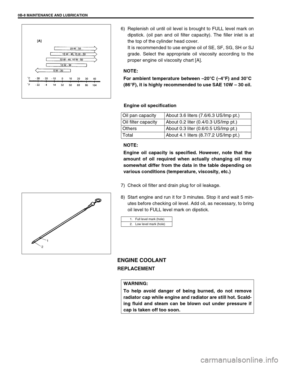
6) Replenish oil until oil level is brought to FULL level mark on
dipstick. (oil pan and oil filter capacity). The filler inlet is at
the top of the cylinder head cover.
It is recommended to use engine oil of SE, SF, SG, SH or SJ
grade. Select the appropriate oil viscosity according to the
proper engine oil viscosity chart [A].
Engine oil specification
7) Check oil filter and drain plug for oil leakage.
8) Start engine and run it for 3 minutes. Stop it and wait 5 min-
utes before checking oil level. Add oil, as necessary, to bring
oil level to FULL level mark on dipstick.
ENGINE COOLANT
REPLACEMENT
NOTE:
For ambient temperature between –20°C (–4°F) and 30°C
(86°F), it is highly recommended to use SAE 10W – 30 oil.
Oil pan capacity About 3.6 liters (7.6/6.3 US/lmp pt.)
Oil filter capacity About 0.2 liter (0.4/0.3 US/lmp pt.)
Others About 0.3 liter (0.6/0.5 US/lmp pt.)
Total About 4.1 liters (8.7/7.2 US/lmp pt.)
NOTE:
Engine oil capacity is specified. However, note that the
amount of oil required when actually changing oil may
somewhat differ from the data in the table depending on
various conditions (temperature, viscosity, etc.)
1. Full level mark (hole)
2. Low level mark (hole)
WARNING:
To help avoid danger of being burned, do not remove
radiator cap while engine and radiator are still hot. Scald-
ing fluid and steam can be blown out under pressure if
cap is taken off too soon.
Page 38 of 698
MAINTENANCE AND LUBRICATION 0B-9
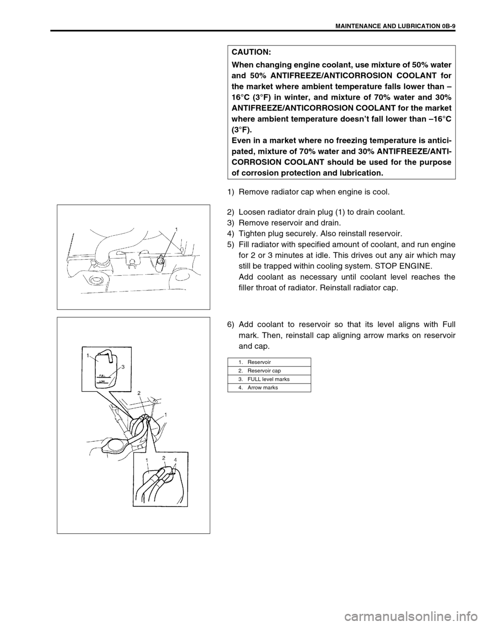
1) Remove radiator cap when engine is cool.
2) Loosen radiator drain plug (1) to drain coolant.
3) Remove reservoir and drain.
4) Tighten plug securely. Also reinstall reservoir.
5) Fill radiator with specified amount of coolant, and run engine
for 2 or 3 minutes at idle. This drives out any air which may
still be trapped within cooling system. STOP ENGINE.
Add coolant as necessary until coolant level reaches the
filler throat of radiator. Reinstall radiator cap.
6) Add coolant to reservoir so that its level aligns with Full
mark. Then, reinstall cap aligning arrow marks on reservoir
and cap. CAUTION:
When changing engine coolant, use mixture of 50% water
and 50% ANTIFREEZE/ANTICORROSION COOLANT for
the market where ambient temperature falls lower than –
16°C (3°F) in winter, and mixture of 70% water and 30%
ANTIFREEZE/ANTICORROSION COOLANT for the market
where ambient temperature doesn’t fall lower than –16°C
(3°F).
Even in a market where no freezing temperature is antici-
pated, mixture of 70% water and 30% ANTIFREEZE/ANTI-
CORROSION COOLANT should be used for the purpose
of corrosion protection and lubrication.
1. Reservoir
2. Reservoir cap
3. FULL level marks
4. Arrow marks
Page 391 of 698
6-22 ENGINE GENERAL INFORMATION AND DIAGNOSIS
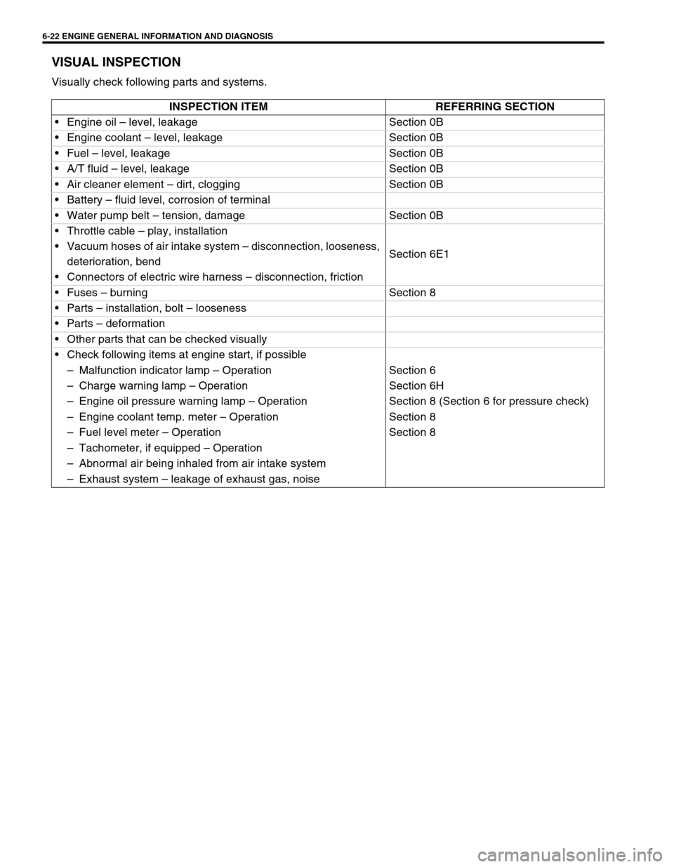
VISUAL INSPECTION
Visually check following parts and systems.
INSPECTION ITEM REFERRING SECTION
Engine oil – level, leakage Section 0B
Engine coolant – level, leakage Section 0B
Fuel – level, leakage Section 0B
A/T fluid – level, leakage Section 0B
Air cleaner element – dirt, clogging Section 0B
Battery – fluid level, corrosion of terminal
Water pump belt – tension, damage Section 0B
Throttle cable – play, installation
Section 6E1 Vacuum hoses of air intake system – disconnection, looseness,
deterioration, bend
Connectors of electric wire harness – disconnection, friction
Fuses – burning Section 8
Parts – installation, bolt – looseness
Parts – deformation
Other parts that can be checked visually
Check following items at engine start, if possible
–Malfunction indicator lamp – Operation Section 6
–Charge warning lamp – Operation Section 6H
–Engine oil pressure warning lamp – Operation Section 8 (Section 6 for pressure check)
–Engine coolant temp. meter – Operation Section 8
–Fuel level meter – Operation Section 8
–Tachometer, if equipped – Operation
–Abnormal air being inhaled from air intake system
–Exhaust system – leakage of exhaust gas, noise
Page 402 of 698

ENGINE GENERAL INFORMATION AND DIAGNOSIS 6-33
SCAN TOOL DATA DEFINITIONS :
FUEL SYSTEM (FUEL SYSTEM STATUS)
Air/fuel ratio feedback loop status displayed as either open or closed loop. Open indicates that ECM ignores
feedback from the exhaust oxygen sensor.
Closed indicates final injection duration is corrected for oxygen sensor feedback.
CALC LOAD (CALCULATED LOAD VALUE, %)
Engine load displayed as a percentage of maximum possible load. Value is calculated mathematically using the
formula : actual (current) intake air volume ÷ maximum possible intake air volume x 100%.
COOLANT TEMP. (ENGINE COOLANT TEMPERATURE, °C, °F)
It is detected by engine coolant temp. sensor
SHORT FT B1 (SHORT TERM FUEL TRIM, %)
Short term fuel trim value represents short term corrections to the air/fuel mixture computation. A value of 0 indi-
cates no correction, a value greater than 0 means an enrichment correction, and a value less than 0 implies an
enleanment correction.
LONG FT B1 (LONG TERM FUEL TRIM, %)
Long term fuel trim Value represents long term corrections to the air/fuel mixture computation. A value of 0 indi-
cates no correction, a value greater than 0 means an enrichment correction, and a value less than 0 implies an
enleanment correction.
MAP (INTAKE MANIFOLD ABSOLUTE PRESSURE, kPa, inHg)
It is detected by manifold absolute pressure sensor and used (among other things) to compute engine load.
ENGINE SPEED (rpm)
It is computed by reference pulses from crankshaft position sensor.
VEHICLE SPEED (km/h, MPH)
It is computed based on pulse signals from vehicle speed sensor.PNP SIGNAL (PARK/NEU-
TRAL POSITION SIGNAL)
A/T onlyIgnition switch
ONSelector lever in “P” or “N”
positionP/N Range
Selector lever in “R”, “D”,
“2” or “L” positionD Range
EGR VALVE At specified idle speed after warming up 0%
∆FUEL TANK LEVEL–0 – 100%
BAROMETRIC PRESS–Display the barometric pres-
sure
FUEL PUMP Within 3 seconds after ignition switch ON or
engine runningON
Engine stop at ignition switch ON. OFF
BRAKE SW Ignition switch
ONBrake pedal is depressing ON
Brake pedal is releasing OFF
BLOWER FAN Ignition switch
ONBlower fan switch ON ON
Blower fan switch OFF OFF
A/C MAG CLUTCH Ignition switch
ONA/C switch ON ON
A/C switch OFF OFF SCAN TOOL DATA VEHICLE CONDITION NORMAL CONDITION/
REFERENCE VALUES
Page 408 of 698
ENGINE GENERAL INFORMATION AND DIAGNOSIS 6-39
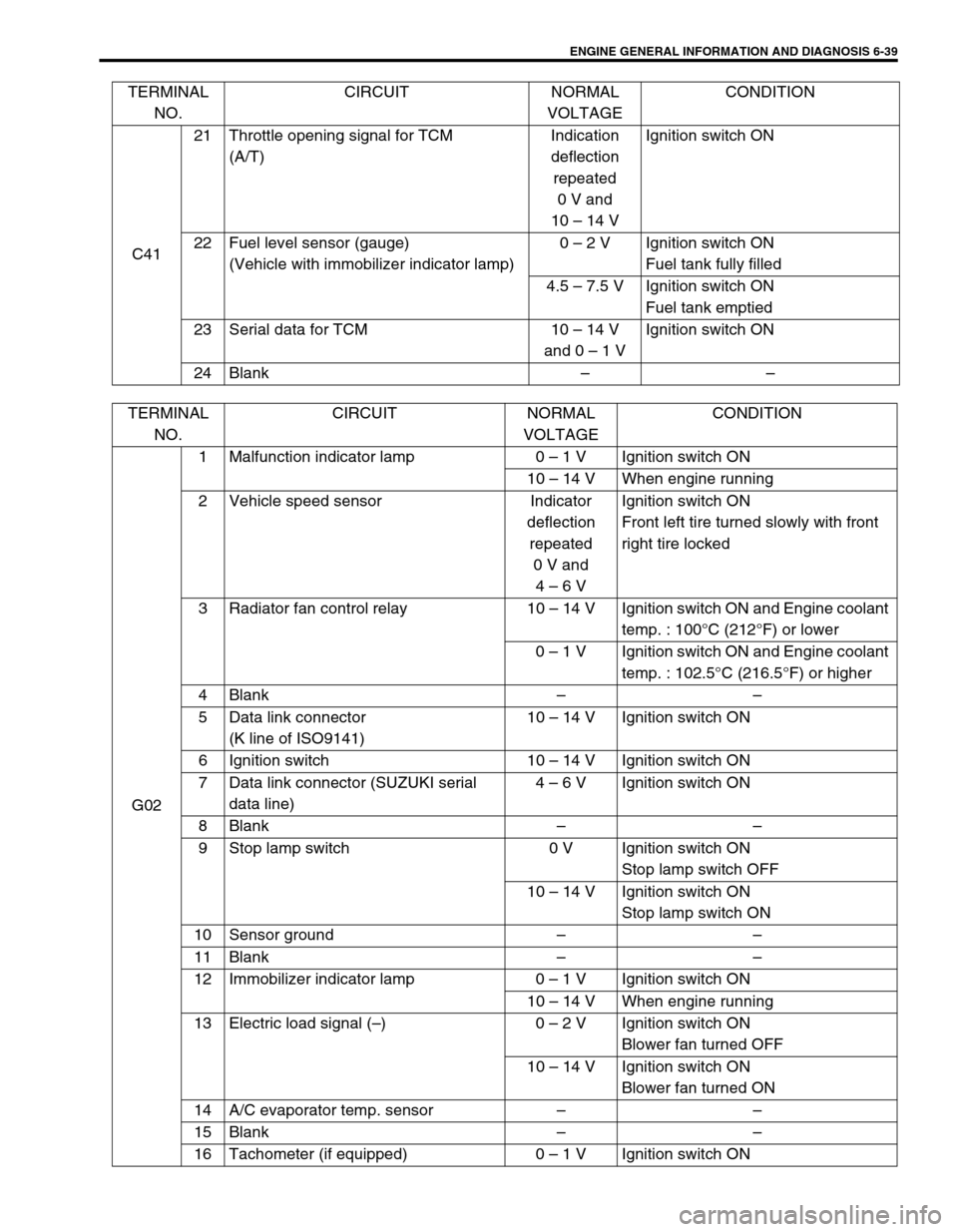
C4121 Throttle opening signal for TCM
(A/T)Indication
deflection
repeated
0 V and
10 – 14 VIgnition switch ON
22 Fuel level sensor (gauge)
(Vehicle with immobilizer indicator lamp)0 – 2 V Ignition switch ON
Fuel tank fully filled
4.5 – 7.5 V Ignition switch ON
Fuel tank emptied
23 Serial data for TCM 10 – 14 V
and 0 – 1 VIgnition switch ON
24 Blank–– TERMINAL
NO.CIRCUIT NORMAL
VOLTAGECONDITION
TERMINAL
NO.CIRCUIT NORMAL
VOLTAGECONDITION
G021 Malfunction indicator lamp 0 – 1 V Ignition switch ON
10 – 14 V When engine running
2 Vehicle speed sensor Indicator
deflection
repeated
0 V and
4 – 6 VIgnition switch ON
Front left tire turned slowly with front
right tire locked
3 Radiator fan control relay 10 – 14 V Ignition switch ON and Engine coolant
temp. : 100°C (212°F) or lower
0 – 1 V Ignition switch ON and Engine coolant
temp. : 102.5°C (216.5°F) or higher
4 Blank––
5 Data link connector
(K line of ISO9141)10 – 14 V Ignition switch ON
6 Ignition switch 10 – 14 V Ignition switch ON
7 Data link connector (SUZUKI serial
data line)4 – 6 V Ignition switch ON
8 Blank––
9 Stop lamp switch 0 V Ignition switch ON
Stop lamp switch OFF
10 – 14 V Ignition switch ON
Stop lamp switch ON
10 Sensor ground––
11 Blank––
12 Immobilizer indicator lamp 0 – 1 V Ignition switch ON
10 – 14 V When engine running
13 Electric load signal (–)0 – 2 V Ignition switch ON
Blower fan turned OFF
10 – 14 V Ignition switch ON
Blower fan turned ON
14 A/C evaporator temp. sensor––
15 Blank––
16 Tachometer (if equipped) 0 – 1 V Ignition switch ON
Page 432 of 698

ENGINE GENERAL INFORMATION AND DIAGNOSIS 6-63
DTC P0121 THROTTLE POSITION CIRCUIT RANGE/PERFORMANCE PROB-
LEM
WIRING DIAGRAM / CIRCUIT DESCRIPTION
DTC CONFIRMATION PROCEDURE
1) Turn ignition switch OFF. Clear DTC with ignition switch ON, check vehicle and environmental condition for :
–Altitude (barometric pressure) : 2400 m, 8000 ft or less (560 mmHg, 75 kPa or more)
–Ambient temp. : –10°C, 14°F or higher
–Intake air temp. : 70°C, 158°F or lower
–Engine coolant temp. : 70 – 110°C, 158 – 230°F
2) Warm up engine to normal operating temperature.
3) Increase vehicle speed to 30 – 40 mph, 50 – 60 km/h in 3rd gear or “D” range and hold throttle valve at that
opening position for 1 min.
4) Stop vehicle.
5) Check DTC in “DTC” mode and pending DTC in “ON BOARD TEST” or “PENDING DTC” mode.
[A] : Case of TYPE A is shown (See NOTE) [B] : Case of TYPE B is shown (See NOTE)
C42-10
C42-22
5V5V
ECM
GRY/RED
GRY/BLU
ORN
C42 (31P) C41 (24P) G02 (17P)1 2 3 4 5 6 7 8 9
10 11 12 13 14 15 16 17 18 19 20 21
22 23 24 25 26 28 27 29 30 315 6
1 2 3 4 5 6 7
11 12
9 10 11 13 12 14 15 16
16 171 2
7 8
13 14 3 4
9 10
15 17 188
19 20 21 22 23 24
C42-16 [B]C41-3 [A]
NOTE:
For TYPE A and TYPE B, refer to NOTE in “ECM VOLTAGE VALUES TABLE” for applicable model.
DTC DETECTING CONDITION POSSIBLE CAUSE
DTC will set when the following conditions are detected.
After engine warmed up.
While vehicle running at specified engine speed.
No change in intake manifold pressure (constant throttle opening)
Difference between actual throttle opening (detected from TP sensor)
and opening calculated by ECM (Obtained on the basis of engine
speed and intake manifold pressure) in larger than specified value.
✱2 driving cycle detection logic, continuous monitoringTP sensor malfunction
High resistance in the circuit
ECM malfunction
WARNING:
When performing a road test, select a place where there is no traffic or possibility of a traffic acci-
dent and be very careful during testing to avoid occurrence of an accident.
Road test should be carried out with 2 persons, a driver and a tester, on a level road.
Page 467 of 698

6-98 ENGINE GENERAL INFORMATION AND DIAGNOSIS
DTC CONFIRMATION PROCEDURE
1) Turn ignition switch OFF.
Clear DTC with ignition switch ON, check vehicle and environmental condition for :
–Altitude (barometric pressure) : 2400 m, 8000 ft or less (560 mmHg, 75 kPa or more)
–Ambient temp. : –10°C, 14°F or higher
–Intake air temp. : 70°C, 158°F or lower
–Engine coolant temp. : 70 – 110°C, 158 – 230°F
2) Start engine and drive vehicle at 35 – 45 mph, 55 – 65 km/h for 8 min. or longer.
While this driving, if “Catalyst Monitoring TEST COMPLETED” is displayed in “READINESS TESTS” mode
and DTC is not displayed in “DTC” mode, confirmation test is completed.
If “TEST NOT COMPLETE” is still being displayed, continue test driving.
3) Decrease vehicle speed at 30 – 40 mph, 50 – 60 km/h, and hold throttle valve at that opening position for 2
min. and confirm that short term fuel trim vary within – 20% – +20% range.
4) Stop vehicle (do not turn ignition switch OFF) and confirm test results according to following “Test Result
Confirmation Flow Table”.
TEST RESULT CONFIRMATION FLOW TABLE
WARNING:
When performing a road test, select a place where there is no traffic or possibility of a traffic acci-
dent and be very careful during testing to avoid occurrence of an accident.
Road test should be carried out with 2 persons, a driver and tester, on a level road.
Step Action Yes No
1 Check DTC in “DTC” mode and pending DTC in
“ON BOARD TEST” or “PENDING DTC” mode.
Is DTC or pending DTC displayed?Proceed to applicable
DTC Diag. Flow Table.Go to Step 2.
2 Set scan tool to “READINESS TESTS” mode
and check if testing has been completed.
Is test completed?No DTC is detected (con-
firmation test is com-
pleted).Repeat DTC confirmation
procedure.
Page 590 of 698
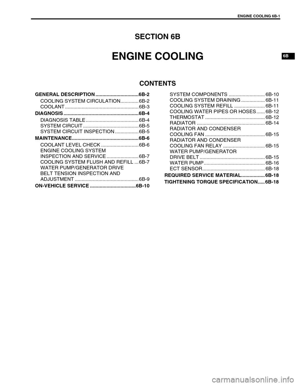
ENGINE COOLING 6B-1
6B
SECTION 6B
ENGINE COOLING
CONTENTS
GENERAL DESCRIPTION ...............................6B-2
COOLING SYSTEM CIRCULATION............. 6B-2
COOLANT ..................................................... 6B-3
DIAGNOSIS ......................................................6B-4
DIAGNOSIS TABLE ...................................... 6B-4
SYSTEM CIRCUIT ........................................ 6B-5
SYSTEM CIRCUIT INSPECTION ................. 6B-5
MAINTENANCE................................................6B-6
COOLANT LEVEL CHECK ........................... 6B-6
ENGINE COOLING SYSTEM
INSPECTION AND SERVICE ....................... 6B-7
COOLING SYSTEM FLUSH AND REFILL ... 6B-7
WATER PUMP/GENERATOR DRIVE
BELT TENSION INSPECTION AND
ADJUSTMENT .............................................. 6B-9
ON-VEHICLE SERVICE .................................6B-10SYSTEM COMPONENTS .......................... 6B-10
COOLING SYSTEM DRAINING ................. 6B-11
COOLING SYSTEM REFILL ...................... 6B-11
COOLING WATER PIPES OR HOSES ...... 6B-12
THERMOSTAT ........................................... 6B-12
RADIATOR ................................................. 6B-14
RADIATOR AND CONDENSER
COOLING FAN ........................................... 6B-15
RADIATOR AND CONDENSER
COOLING FAN RELAY .............................. 6B-15
WATER PUMP/GENERATOR
DRIVE BELT ............................................... 6B-15
WATER PUMP............................................ 6B-16
ECT SENSOR............................................. 6B-18
REQUIRED SERVICE MATERIAL................. 6B-18
TIGHTENING TORQUE SPECIFICATION..... 6B-18