2000 SUZUKI SWIFT coolant level
[x] Cancel search: coolant levelPage 593 of 698
6B-4 ENGINE COOLING
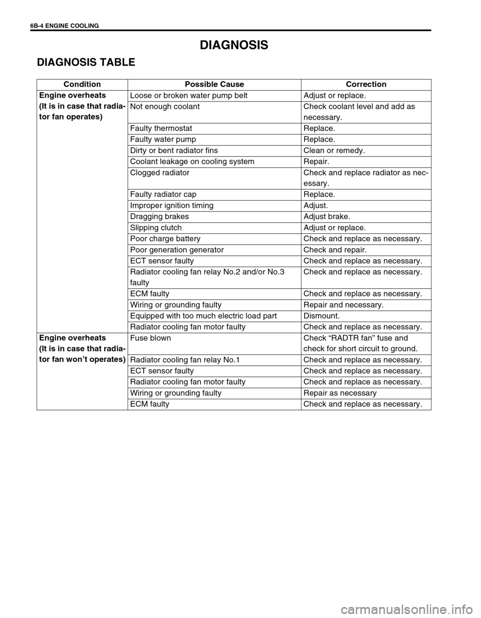
DIAGNOSIS
DIAGNOSIS TABLE
Condition Possible Cause Correction
Engine overheats
(It is in case that radia-
tor fan operates)Loose or broken water pump belt Adjust or replace.
Not enough coolant Check coolant level and add as
necessary.
Faulty thermostat Replace.
Faulty water pump Replace.
Dirty or bent radiator fins Clean or remedy.
Coolant leakage on cooling system Repair.
Clogged radiator Check and replace radiator as nec-
essary.
Faulty radiator cap Replace.
Improper ignition timing Adjust.
Dragging brakes Adjust brake.
Slipping clutch Adjust or replace.
Poor charge battery Check and replace as necessary.
Poor generation generator Check and repair.
ECT sensor faulty Check and replace as necessary.
Radiator cooling fan relay No.2 and/or No.3
faultyCheck and replace as necessary.
ECM faulty Check and replace as necessary.
Wiring or grounding faulty Repair and necessary.
Equipped with too much electric load part Dismount.
Radiator cooling fan motor faulty Check and replace as necessary.
Engine overheats
(It is in case that radia-
tor fan won’t operates)Fuse blown Check “RADTR fan” fuse and
check for short circuit to ground.
Radiator cooling fan relay No.1 Check and replace as necessary.
ECT sensor faulty Check and replace as necessary.
Radiator cooling fan motor faulty Check and replace as necessary.
Wiring or grounding faulty Repair as necessary
ECM faulty Check and replace as necessary.
Page 595 of 698
6B-6 ENGINE COOLING
MAINTENANCE
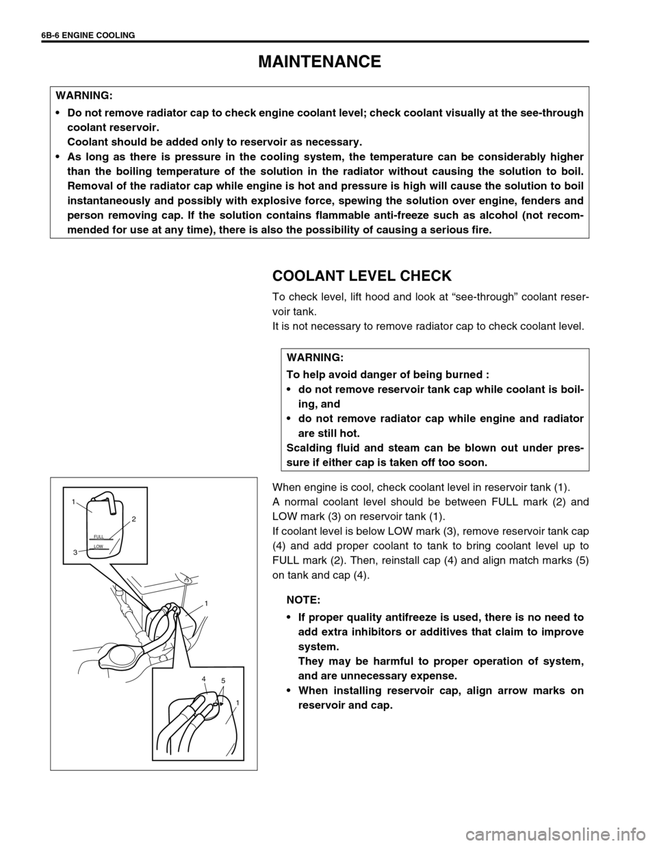
COOLANT LEVEL CHECK
To check level, lift hood and look at “see-through” coolant reser-
voir tank.
It is not necessary to remove radiator cap to check coolant level.
When engine is cool, check coolant level in reservoir tank (1).
A normal coolant level should be between FULL mark (2) and
LOW mark (3) on reservoir tank (1).
If coolant level is below LOW mark (3), remove reservoir tank cap
(4) and add proper coolant to tank to bring coolant level up to
FULL mark (2). Then, reinstall cap (4) and align match marks (5)
on tank and cap (4). WARNING:
Do not remove radiator cap to check engine coolant level; check coolant visually at the see-through
coolant reservoir.
Coolant should be added only to reservoir as necessary.
As long as there is pressure in the cooling system, the temperature can be considerably higher
than the boiling temperature of the solution in the radiator without causing the solution to boil.
Removal of the radiator cap while engine is hot and pressure is high will cause the solution to boil
instantaneously and possibly with explosive force, spewing the solution over engine, fenders and
person removing cap. If the solution contains flammable anti-freeze such as alcohol (not recom-
mended for use at any time), there is also the possibility of causing a serious fire.
WARNING:
To help avoid danger of being burned :
do not remove reservoir tank cap while coolant is boil-
ing, and
do not remove radiator cap while engine and radiator
are still hot.
Scalding fluid and steam can be blown out under pres-
sure if either cap is taken off too soon.
NOTE:
If proper quality antifreeze is used, there is no need to
add extra inhibitors or additives that claim to improve
system.
They may be harmful to proper operation of system,
and are unnecessary expense.
When installing reservoir cap, align arrow marks on
reservoir and cap.
LOW FULL
5 41
1 32 1
Page 596 of 698
ENGINE COOLING 6B-7
ENGINE COOLING SYSTEM INSPECTION
AND SERVICE
1) Check cooling system for leakage or damage.
2) Wash radiator cap and filler neck with clean water by remov-
ing radiator cap when engine is cold.
3) Check coolant for proper level and freeze protection.
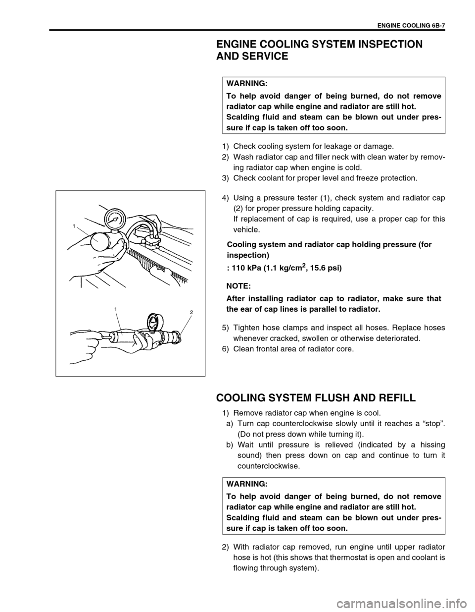
4) Using a pressure tester (1), check system and radiator cap
(2) for proper pressure holding capacity.
If replacement of cap is required, use a proper cap for this
vehicle.
Cooling system and radiator cap holding pressure (for
inspection)
: 110 kPa (1.1 kg/cm
2, 15.6 psi)
5) Tighten hose clamps and inspect all hoses. Replace hoses
whenever cracked, swollen or otherwise deteriorated.
6) Clean frontal area of radiator core.
COOLING SYSTEM FLUSH AND REFILL
1) Remove radiator cap when engine is cool.
a) Turn cap counterclockwise slowly until it reaches a “stop”.
(Do not press down while turning it).
b) Wait until pressure is relieved (indicated by a hissing
sound) then press down on cap and continue to turn it
counterclockwise.
2) With radiator cap removed, run engine until upper radiator
hose is hot (this shows that thermostat is open and coolant is
flowing through system). WARNING:
To help avoid danger of being burned, do not remove
radiator cap while engine and radiator are still hot.
Scalding fluid and steam can be blown out under pres-
sure if cap is taken off too soon.
NOTE:
After installing radiator cap to radiator, make sure that
the ear of cap lines is parallel to radiator.
WARNING:
To help avoid danger of being burned, do not remove
radiator cap while engine and radiator are still hot.
Scalding fluid and steam can be blown out under pres-
sure if cap is taken off too soon.
Page 597 of 698

6B-8 ENGINE COOLING
3) Stop engine and drain coolant.
4) Close drain plug. Add water until system is filled and run
engine until upper radiator hose is hot again.
5) Repeat Steps 3) and 4) several times until drained liquid is
nearly colorless.
6) Drain system and then close radiator drain plug (1) tightly.
7) Remove reservoir tank (1) and remove cap (2) from reservoir
tank (1) and pour out any fluid, scrub and clean inside of
tank with soap and water.
Flush it well with clean water and drain. Reinstall tank.
8) Add coolant that is a mixture of good quality ethylene glycol
antifreeze and water to radiator and reservoir tank. For cool-
ant concentration referring to “COOLANT”.
Fill radiator to the bottom of filler neck and reservoir tank to
FULL level mark (3).
9) Reinstall reservoir tank cap and align match marks (4) on
reservoir tank and its tank cap.
10) Run engine with radiator cap removed, until radiator inlet
hose is hot.
11) With engine idling, add coolant to radiator until level reaches
the bottom of filler neck. Install radiator cap, making sure
that the ear of cap lines is parallel to radiator.
1
LOW FULL
4 1
1 3
2
2 1
Page 600 of 698

ENGINE COOLING 6B-11
COOLING SYSTEM DRAINING
1) Remove radiator cap.
2) Loosen drain plug (1) of radiator to drain coolant.
3) After draining coolant, be sure to tighten drain plug securely.
COOLING SYSTEM REFILL
1) Be sure to tighten drain plug (1) securely.
2) Add coolant that is a mixture of good quality ethylene glycol
antifreeze and water to radiator and reservoir tank (2). For
coolant concentration, referring to “COOLANT”.
Fill radiator to the bottom of filler neck and reservoir tank (2)
to FULL level mark (3).
3) Reinstall reservoir tank cap (4) and align match marks (5) on
reservoir tank (2) and its tank cap (4).
4) Run engine with radiator cap (7) removed, until radiator inlet
hose (6) is hot.
5) With engine idling, add coolant to radiator until level reaches
the bottom of filler neck.
6) Install radiator cap (7) make sure that the ear of radiator cap
(7) lines is parallel to radiator.
1
LOW FULL
5 2
7 6
2 3
4
4
1
Page 623 of 698
6E1-2 ENGINE AND EMISSION CONTROL SYSTEM
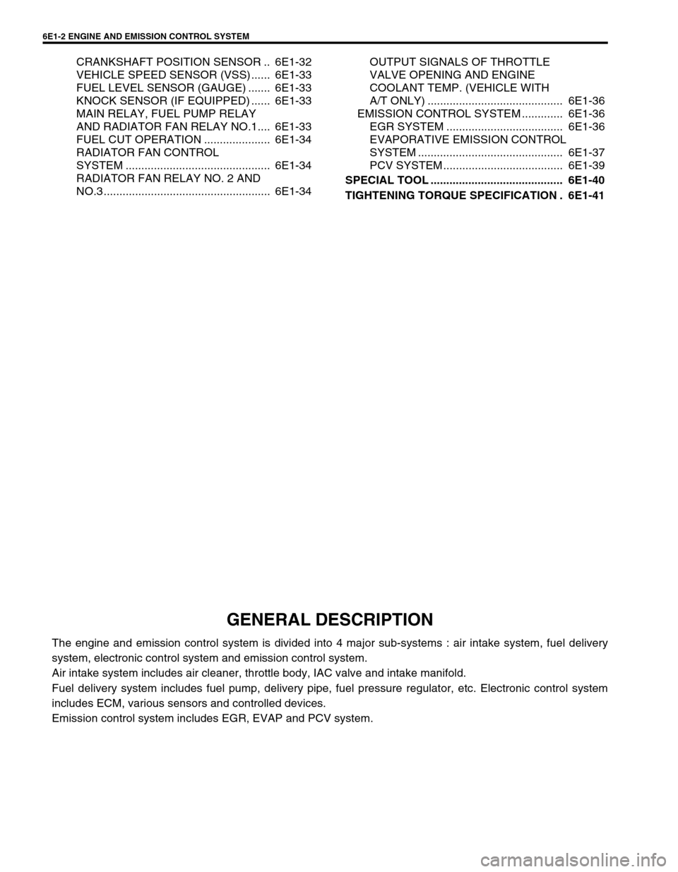
CRANKSHAFT POSITION SENSOR .. 6E1-32
VEHICLE SPEED SENSOR (VSS) ...... 6E1-33
FUEL LEVEL SENSOR (GAUGE) ....... 6E1-33
KNOCK SENSOR (IF EQUIPPED) ...... 6E1-33
MAIN RELAY, FUEL PUMP RELAY
AND RADIATOR FAN RELAY NO.1.... 6E1-33
FUEL CUT OPERATION ..................... 6E1-34
RADIATOR FAN CONTROL
SYSTEM .............................................. 6E1-34
RADIATOR FAN RELAY NO. 2 AND
NO.3 ..................................................... 6E1-34OUTPUT SIGNALS OF THROTTLE
VALVE OPENING AND ENGINE
COOLANT TEMP. (VEHICLE WITH
A/T ONLY) ........................................... 6E1-36
EMISSION CONTROL SYSTEM ............. 6E1-36
EGR SYSTEM ..................................... 6E1-36
EVAPORATIVE EMISSION CONTROL
SYSTEM .............................................. 6E1-37
PCV SYSTEM ...................................... 6E1-39
SPECIAL TOOL .......................................... 6E1-40
TIGHTENING TORQUE SPECIFICATION . 6E1-41
GENERAL DESCRIPTION
The engine and emission control system is divided into 4 major sub-systems : air intake system, fuel delivery
system, electronic control system and emission control system.
Air intake system includes air cleaner, throttle body, IAC valve and intake manifold.
Fuel delivery system includes fuel pump, delivery pipe, fuel pressure regulator, etc. Electronic control system
includes ECM, various sensors and controlled devices.
Emission control system includes EGR, EVAP and PCV system.
Page 628 of 698
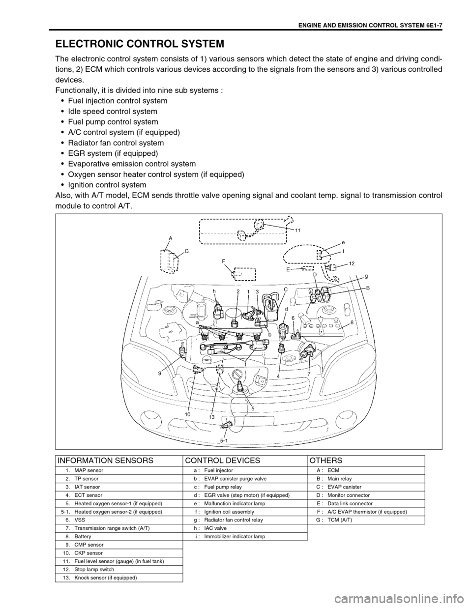
ENGINE AND EMISSION CONTROL SYSTEM 6E1-7
ELECTRONIC CONTROL SYSTEM
The electronic control system consists of 1) various sensors which detect the state of engine and driving condi-
tions, 2) ECM which controls various devices according to the signals from the sensors and 3) various controlled
devices.
Functionally, it is divided into nine sub systems :
Fuel injection control system
Idle speed control system
Fuel pump control system
A/C control system (if equipped)
Radiator fan control system
EGR system (if equipped)
Evaporative emission control system
Oxygen sensor heater control system (if equipped)
Ignition control system
Also, with A/T model, ECM sends throttle valve opening signal and coolant temp. signal to transmission control
module to control A/T.
INFORMATION SENSORS CONTROL DEVICES OTHERS
1. MAP sensor a : Fuel injector A : ECM
2. TP sensor b : EVAP canister purge valve B : Main relay
3. IAT sensor c : Fuel pump relay C : EVAP canister
4. ECT sensor d : EGR valve (step motor) (if equipped) D : Monitor connector
5. Heated oxygen sensor-1 (if equipped) e : Malfunction indicator lamp E : Data link connector
5-1. Heated oxygen sensor-2 (if equipped) f : Ignition coil assembly F : A/C EVAP thermistor (if equipped)
6. VSS g : Radiator fan control relay G : TCM (A/T)
7. Transmission range switch (A/T) h : IAC valve
8. Battery i : Immobilizer indicator lamp
9. CMP sensor
10. CKP sensor
11. Fuel level sensor (gauge) (in fuel tank)
12. Stop lamp switch
13. Knock sensor (if equipped)
Page 634 of 698

ENGINE AND EMISSION CONTROL SYSTEM 6E1-13
ECM TERMINAL ARRANGEMENT TABLE
For TYPE A (Refer to NOTE in page “ECM INPUT/OUTPUT CIRCUIT DIAGRAM” for applicable model.)
CONNEC-
TORTERMINAL WIRE COLOR CIRCUITCONNEC-
TORTERMINAL WIRE COLOR CIRCUIT
C421 BLK/ORN Ground for ECM
C4112––
2 BLK Ground for drive circuit 13–Heated oxygen sensor-2
3 BLK/ORN Ground for drive circuit 14 LT BLU“D”, “2”, “L”-range ID-UP signal
4 BLU/BLK Canister purge valve 15 RED“R”-range signal
5 WHT/BLK Coolant temp. signal output 16 YEL/GRN A/C SW signal
6 GRN/RED IAC valve 17 BRN/YEL EGR valve (stepper motor coil 4)
7 RED/BLU Heater of HO2S-1 18 BLU Radiator fan relay 1
8 BLU/ORN No.4 fuel injector 19 PNK Fuel pump relay
9 BLU/YEL No.1 fuel injector 20––
10 ORN Ground for sensor circuit 21 PPL Throttle opening signal output for A/T
11 RED/YEL CMP sensor 22 YEL/RED Fuel level gauge
12 RED Knock sensor (if equipped) 23 BLK/WHT TCM serial data line
13 WHTHeated oxygen sensor-1
(if equipped)
24––
CO adjusting resistor
(if equipped)
14 LT GRN Coolant temp. sensor
15 LT GRN/BLK Intake air temp. sensor
G021 PPL/WHT Malfunction indicator lamp
16 WHT/GRN Test switch terminal (if equipped) 2 PPL Vehicle speed sensor
17 RED/BLK Electric load (+) 3 PPL/YEL Radiator fan relay 2
18 PNK/GRN A/C switch 4––
19 GRN/WHTIG coil assembly for No.2 and 3 spark
plugs5 BLU Data link connector
20 GRN/YELIG coil assembly for No.1 and 4 spark
plugs6 BLK/WHT Ignition switch signal
21 BLU/WHT No.2 fuel injector 7 YEL Data link connector
22 GRY/RED Power supply for sensor 8––
23 YEL/BLK CKP sensor (+) 9 GRN/WHTStop lamp switch (Brake pedal
switch)
24––10 ORN GND for sensor
25–Ground for sensor shield wire 11––
26 RED/WHT MAP sensor 12 PNKImmobilizer indicator lamp
(if equipped)
27 PPL/WHTDiagnosis switch terminal
(if equipped)13 PNK/BLU Electrical load (-)
28 PNK/BLU Duty output terminal (if equipped) 14 WHT/BLK A/C evaporator temp. sensor
29 BRN Heater of HO2S-2 15––
30 GRN/BLK Heated oxygen sensor-2 16 BRN Tachometer signal
31 BLU/RED No.3 fuel injector 17 WHT/RED Backup power source
C411 PNK/BLK A/C compressor clutch
2 GRN EGR valve (stepper motor coil 1)
3 GRY/BLU Throttle position (TP) sensor
4–Heater of HO2S-2
5 BLK/RED Power source
6 BLK/RED Power source
7 BLK/YEL Engine start signal
8 WHT/RED EGR valve (stepper motor coil 3)
9 GRN/ORN EGR valve (stepper motor coil 2)
10 BRN/WHT Ground for main relay
11––
C42 (31P) C41 (24P) G02 (17P)1 2 3 4 5 6 7 8 9
10 11 12 13 14 15 16 17 18 19 20 21
22 23 24 25 26 28 27 29 30 315 6
1 2 3 4 5 6 7
11 12
9 10 11 13 12 14 15 16
16 171 2
7 8
13 14 3 4
9 10
15 17 188
19 20 21 22 23 24
NOTE:
For abbreviation of wire color, refer to Section 0A.