2000 SUZUKI SWIFT fuel filter location
[x] Cancel search: fuel filter locationPage 30 of 698

MAINTENANCE AND LUBRICATION 0B-1
0A 6F1
0B
0B
6G
1A 6H
1B 6K
37A
3A 7A1
3B1 7B1
3C1 7C1
3D 7D
3E 7E
3F 7F
4A2 8A
4B 8B
8C
58D
5A 8E
5B
5C 9
5E
5E1 10
10A
610B
6-1
6A1
6A2
6A4
6B
6C
6E1
6E2
SECTION 0B
MAINTENANCE AND LUBRICATION
CONTENTS
MAINTENANCE SCHEDULE .......................... 0B-2
MAINTENANCE SCHEDULE UNDER
NORMAL DRIVING CONDITIONS .............. 0B-2
MAINTENANCE RECOMMENDED UNDER
SEVERE DRIVING CONDITIONS ............... 0B-4
MAINTENANCE SERVICE .............................. 0B-5
ENGINE ....................................................... 0B-5
DRIVE BELT ............................................ 0B-5
VALVE LASH (CLEARANCE) .................. 0B-6
ENGINE OIL AND OIL FILTER ................ 0B-6
ENGINE COOLANT ................................. 0B-8
EXHAUST SYSTEM............................... 0B-10
IGNITION SYSTEM ................................... 0B-10
SPARK PLUGS ...................................... 0B-10
FUEL SYSTEM .......................................... 0B-10
AIR CLEANER FILTER .......................... 0B-10
FUEL LINES AND CONNECTIONS....... 0B-11
FUEL FILTER ......................................... 0B-11
FUEL TANK............................................ 0B-12
EMISSION CONTROL SYSTEM ............... 0B-12
PCV VALVE ........................................... 0B-12
FUEL EVAPORATIVE EMISSION
CONTROL SYSTEM .............................. 0B-12BRAKE ....................................................... 0B-12
BRAKE DISCS AND PADS (FRONT) .... 0B-12
BRAKE DRUMS AND SHOES
(REAR) ................................................... 0B-13
BRAKE HOSES AND PIPES ................. 0B-13
BRAKE FLUID........................................ 0B-13
BRAKE LEVER AND CABLE ................. 0B-13
CHASSIS AND BODY ............................... 0B-14
CLUTCH................................................. 0B-14
TIRES / WHEELS .................................. 0B-14
SUSPENSION SYSTEM ........................ 0B-15
STEERING SYSTEM ............................. 0B-15
DRIVE SHAFT (AXLE) BOOTS /
PROPELLER SHAFTS (4WD) ............... 0B-16
MANUAL TRANSMISSION OIL ............. 0B-17
AUTOMATIC TRANSMISSION FLUID .. 0B-17
TRANSFER OIL (4WD) AND REAR
DIFFERENTIAL OIL (4WD) ................... 0B-18
ALL LATCHES, HINGES AND
LOCKS ................................................... 0B-19
FINAL INSPECTION ..................................... 0B-19
RECOMMENDED FLUIDS AND
LUBRICANTS................................................ 0B-21
WARNING:
For vehicles equipped with Supplemental Restraint (Air Bag) System:
Service on and around the air bag system components or wiring must be performed only by an
authorized SUZUKI dealer. Refer to “Air Bag System Components and Wiring Location View” under
“General Description” in air bag system section in order to confirm whether you are performing ser-
vice on or near the air bag system components or wiring. Please observe all WARNINGS and “Ser-
vice Precautions” under “On-Vehicle Service” in air bag system section before performing service
on or around the air bag system components or wiring. Failure to follow WARNINGS could result in
unintentional activation of the system or could render the system inoperative. Either of these two
conditions may result in severe injury.
Technical service work must be started at least 90 seconds after the ignition switch is turned to the
“LOCK” position and the negative cable is disconnected from the battery. Otherwise, the system
may be activated by reserve energy in the Sensing and Diagnostic Module (SDM).
Page 397 of 698

6-28 ENGINE GENERAL INFORMATION AND DIAGNOSIS
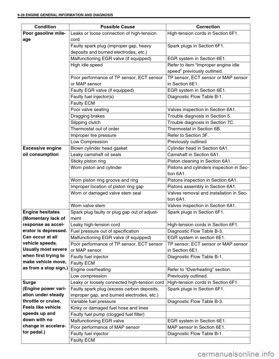
Poor gasoline mile-
age Leaks or loose connection of high-tension
cordHigh-tension cords in Section 6F1.
Faulty spark plug (improper gap, heavy
deposits and burned electrodes, etc.)Spark plugs in Section 6F1.
Malfunctioning EGR valve (if equipped) EGR system in Section 6E1.
High idle speed Refer to item “Improper engine idle
speed” previously outlined.
Poor performance of TP sensor, ECT sensor
or MAP sensorTP sensor, ECT sensor or MAP sensor
in Section 6E1.
Faulty EGR valve (if equipped) EGR system in Section 6E1.
Faulty fuel injector(s) Diagnostic Flow Table B-1.
Faulty ECM
Poor valve seating Valves inspection in Section 6A1.
Dragging brakes Trouble diagnosis in Section 5.
Slipping clutch Trouble diagnosis in Section 7C.
Thermostat out of order Thermostat in Section 6B.
Improper tire pressure Refer to Section 3F.
Low Compression Previously outlined
Excessive engine
oil consumption Blown cylinder head gasket Cylinder head in Section 6A1.
Leaky camshaft oil seals Camshaft in Section 6A1.
Sticky piston ring Piston cleaning in Section 6A1.
Worn piston and cylinder Pistons and cylinders inspection in Sec-
tion 6A1.
Worn piston ring groove and ring Pistons inspection in Section 6A1.
Improper location of piston ring gap Pistons assembly in Section 6A1.
Worn or damaged valve stem seal Valves removal and installation in Sec-
tion 6A1.
Worn valve stem Valves inspection in Section 6A1.
Engine hesitates
(Momentary lack of
response as accel-
erator is depressed.
Can occur at all
vehicle speeds.
Usually most severe
when first trying to
make vehicle move,
as from a stop sign.)Spark plug faulty or plug gap out of adjust-
mentSpark plugs in Section 6F1.
Leaky high-tension cord High-tension cords in Section 6F1.
Fuel pressure out of specification Diagnostic Flow Table B-3.
Malfunctioning EGR valve (if equipped) EGR system in section 6E1.
Poor performance of TP sensor, ECT sensor
or MAP sensorTP sensor, ECT sensor or MAP sensor
in Section 6E1.
Faulty fuel injector Diagnostic Flow Table B-1.
Faulty ECM
Engine overheating Refer to “Overheating” section.
Low compression Previously outlined.
Surge
(Engine power vari-
ation under steady
throttle or cruise.
Feels like vehicle
speeds up and
down with no
change in accelera-
tor pedal.)Leaky or loosely connected high-tension cord High-tension cords in Section 6F1.
Faulty spark plug (excess carbon deposits,
improper gap, and burned electrodes, etc.)Spark plugs in Section 6F1.
Variable fuel pressure Diagnostic Flow Table B-3.
Kinky or damaged fuel hose and lines
Faulty fuel pump (clogged fuel filter)
Malfunctioning EGR valve EGR system in Section 6E1.
Poor performance of MAP sensor MAP sensor in Section 6E1.
Faulty fuel injector Diagnostic Flow Table B-1.
Faulty ECM Condition Possible Cause Correction
Page 608 of 698

ENGINE FUEL 6C-1
6F1
6F2
6G
6C
6K
7A
7A1
7B1
7C1
7D
7E
7F
8A
8B
8C
8D
8E
9
10
10A
10B
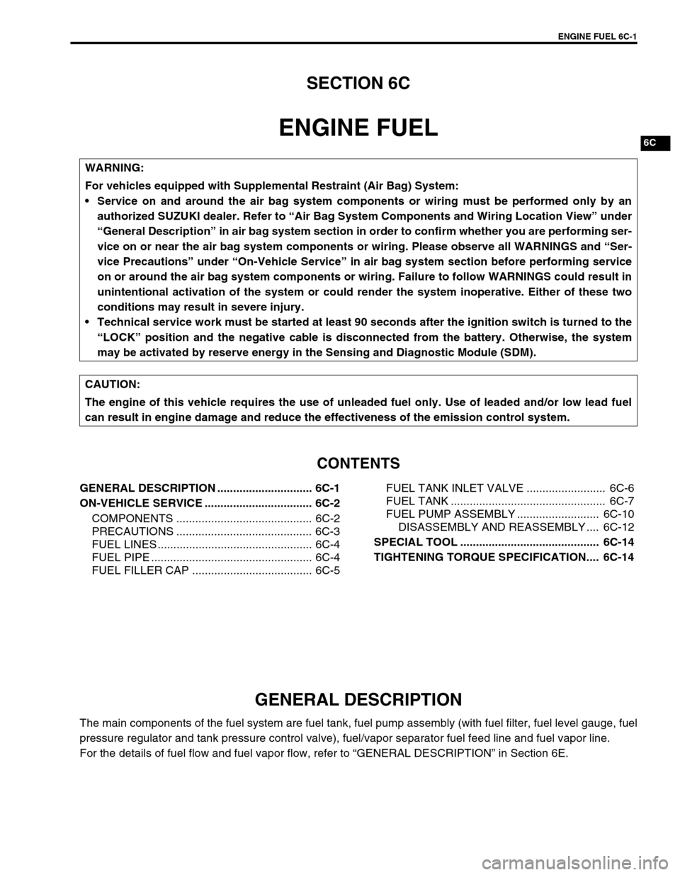
SECTION 6C
ENGINE FUEL
CONTENTS
GENERAL DESCRIPTION .............................. 6C-1
ON-VEHICLE SERVICE .................................. 6C-2
COMPONENTS ........................................... 6C-2
PRECAUTIONS ........................................... 6C-3
FUEL LINES ................................................. 6C-4
FUEL PIPE ................................................... 6C-4
FUEL FILLER CAP ...................................... 6C-5FUEL TANK INLET VALVE ......................... 6C-6
FUEL TANK ................................................. 6C-7
FUEL PUMP ASSEMBLY .......................... 6C-10
DISASSEMBLY AND REASSEMBLY .... 6C-12
SPECIAL TOOL ............................................ 6C-14
TIGHTENING TORQUE SPECIFICATION.... 6C-14
GENERAL DESCRIPTION
The main components of the fuel system are fuel tank, fuel pump assembly (with fuel filter, fuel level gauge, fuel
pressure regulator and tank pressure control valve), fuel/vapor separator fuel feed line and fuel vapor line.
For the details of fuel flow and fuel vapor flow, refer to “GENERAL DESCRIPTION” in Section 6E. WARNING:
For vehicles equipped with Supplemental Restraint (Air Bag) System:
Service on and around the air bag system components or wiring must be performed only by an
authorized SUZUKI dealer. Refer to “Air Bag System Components and Wiring Location View” under
“General Description” in air bag system section in order to confirm whether you are performing ser-
vice on or near the air bag system components or wiring. Please observe all WARNINGS and “Ser-
vice Precautions” under “On-Vehicle Service” in air bag system section before performing service
on or around the air bag system components or wiring. Failure to follow WARNINGS could result in
unintentional activation of the system or could render the system inoperative. Either of these two
conditions may result in severe injury.
Technical service work must be started at least 90 seconds after the ignition switch is turned to the
“LOCK” position and the negative cable is disconnected from the battery. Otherwise, the system
may be activated by reserve energy in the Sensing and Diagnostic Module (SDM).
CAUTION:
The engine of this vehicle requires the use of unleaded fuel only. Use of leaded and/or low lead fuel
can result in engine damage and reduce the effectiveness of the emission control system.