2000 NISSAN PATROL ecm
[x] Cancel search: ecmPage 251 of 1033
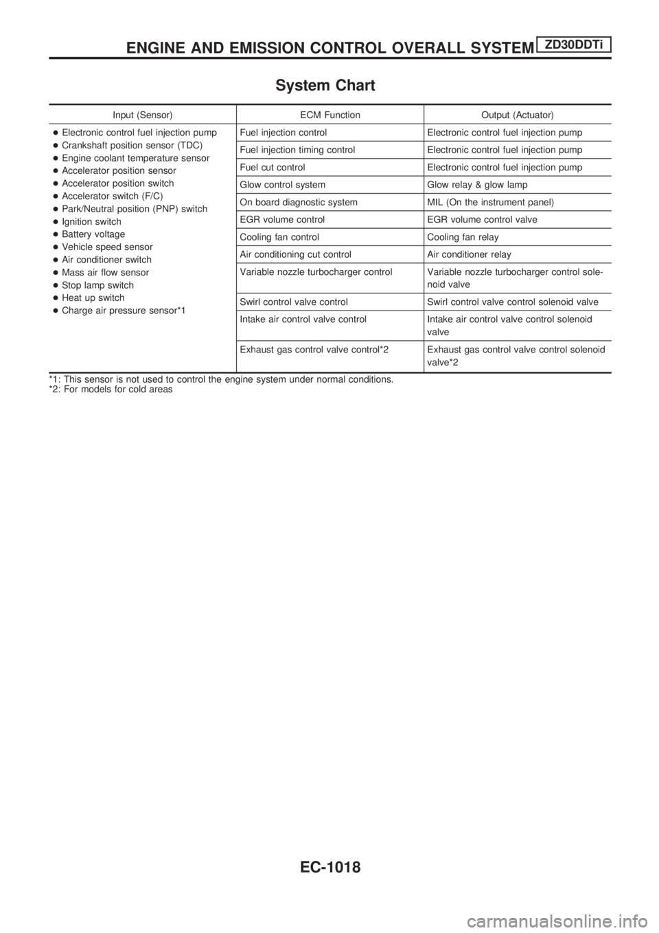
System Chart
Input (Sensor) ECM Function Output (Actuator)
+Electronic control fuel injection pump
+Crankshaft position sensor (TDC)
+Engine coolant temperature sensor
+Accelerator position sensor
+Accelerator position switch
+Accelerator switch (F/C)
+Park/Neutral position (PNP) switch
+Ignition switch
+Battery voltage
+Vehicle speed sensor
+Air conditioner switch
+Mass air flow sensor
+Stop lamp switch
+Heat up switch
+Charge air pressure sensor*1Fuel injection control Electronic control fuel injection pump
Fuel injection timing control Electronic control fuel injection pump
Fuel cut control Electronic control fuel injection pump
Glow control system Glow relay & glow lamp
On board diagnostic system MIL (On the instrument panel)
EGR volume control EGR volume control valve
Cooling fan control Cooling fan relay
Air conditioning cut control Air conditioner relay
Variable nozzle turbocharger control Variable nozzle turbocharger control sole-
noid valve
Swirl control valve control Swirl control valve control solenoid valve
Intake air control valve control Intake air control valve control solenoid
valve
Exhaust gas control valve control*2 Exhaust gas control valve control solenoid
valve*2
*1: This sensor is not used to control the engine system under normal conditions.
*2: For models for cold areas
ENGINE AND EMISSION CONTROL OVERALL SYSTEMZD30DDTi
EC-1018
Page 252 of 1033
Fuel Injection Control System
DESCRIPTION
System description
Three types of fuel injection control are provided to accommodate engine operating conditions; normal
control, idle control and start control. The ECM determines the appropriate fuel injection control. Under each
control, the amount of fuel injected is compensated to improve engine performance.
Pulse signals are exchanged between ECM and electronic control fuel injection pump (control unit is built-
in). The fuel injection pump control unit performs duty control on the spill valve (built into the fuel injection
pump) according to the input signals to compensate the amount of fuel injected to the preset value.
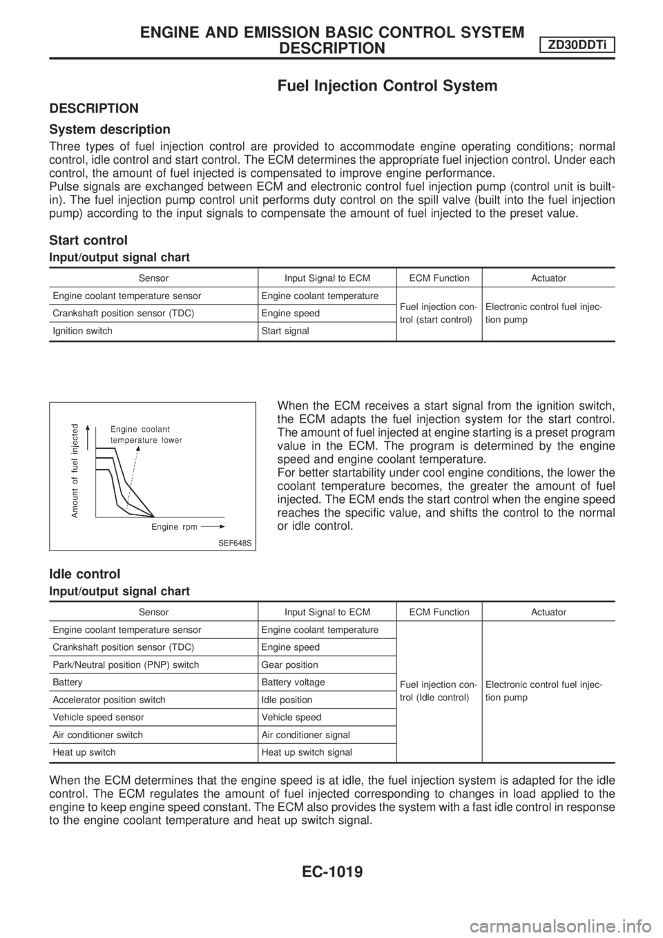
Start control
Input/output signal chart
Sensor Input Signal to ECM ECM Function Actuator
Engine coolant temperature sensor Engine coolant temperature
Fuel injection con-
trol (start control)Electronic control fuel injec-
tion pump Crankshaft position sensor (TDC) Engine speed
Ignition switch Start signal
When the ECM receives a start signal from the ignition switch,
the ECM adapts the fuel injection system for the start control.
The amount of fuel injected at engine starting is a preset program
value in the ECM. The program is determined by the engine
speed and engine coolant temperature.
For better startability under cool engine conditions, the lower the
coolant temperature becomes, the greater the amount of fuel
injected. The ECM ends the start control when the engine speed
reaches the specific value, and shifts the control to the normal
or idle control.
Idle control
Input/output signal chart
Sensor Input Signal to ECM ECM Function Actuator
Engine coolant temperature sensor Engine coolant temperature
Fuel injection con-
trol (Idle control)Electronic control fuel injec-
tion pump Crankshaft position sensor (TDC) Engine speed
Park/Neutral position (PNP) switch Gear position
Battery Battery voltage
Accelerator position switch Idle position
Vehicle speed sensor Vehicle speed
Air conditioner switch Air conditioner signal
Heat up switch Heat up switch signal
When the ECM determines that the engine speed is at idle, the fuel injection system is adapted for the idle
control. The ECM regulates the amount of fuel injected corresponding to changes in load applied to the
engine to keep engine speed constant. The ECM also provides the system with a fast idle control in response
to the engine coolant temperature and heat up switch signal.
SEF648S
ENGINE AND EMISSION BASIC CONTROL SYSTEM
DESCRIPTIONZD30DDTi
EC-1019
Page 253 of 1033
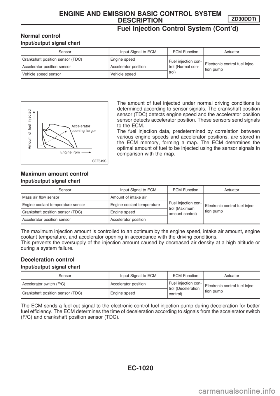
Normal control
Input/output signal chart
Sensor Input Signal to ECM ECM Function Actuator
Crankshaft position sensor (TDC) Engine speed
Fuel injection con-
trol (Normal con-
trol)Electronic control fuel injec-
tion pump Accelerator position sensor Accelerator position
Vehicle speed sensor Vehicle speed
The amount of fuel injected under normal driving conditions is
determined according to sensor signals. The crankshaft position
sensor (TDC) detects engine speed and the accelerator position
sensor detects accelerator position. These sensors send signals
to the ECM.
The fuel injection data, predetermined by correlation between
various engine speeds and accelerator positions, are stored in
the ECM memory, forming a map. The ECM determines the
optimal amount of fuel to be injected using the sensor signals in
comparison with the map.
Maximum amount control
Input/output signal chart
Sensor Input Signal to ECM ECM Function Actuator
Mass air flow sensor Amount of intake air
Fuel injection con-
trol (Maximum
amount control)Electronic control fuel injec-
tion pump Engine coolant temperature sensor Engine coolant temperature
Crankshaft position sensor (TDC) Engine speed
Accelerator position sensor Accelerator position
The maximum injection amount is controlled to an optimum by the engine speed, intake air amount, engine
coolant temperature, and accelerator opening in accordance with the driving conditions.
This prevents the oversupply of the injection amount caused by decreased air density at a high altitude or
during a system failure.
Deceleration control
Input/output signal chart
Sensor Input Signal to ECM ECM Function Actuator
Accelerator switch (F/C) Accelerator positionFuel injection con-
trol (Deceleration
control)Electronic control fuel injec-
tion pump
Crankshaft position sensor (TDC) Engine speed
The ECM sends a fuel cut signal to the electronic control fuel injection pump during deceleration for better
fuel efficiency. The ECM determines the time of deceleration according to signals from the accelerator switch
(F/C) and crankshaft position sensor (TDC).
SEF649S
ENGINE AND EMISSION BASIC CONTROL SYSTEM
DESCRIPTIONZD30DDTi
Fuel Injection Control System (Cont'd)
EC-1020
Page 254 of 1033
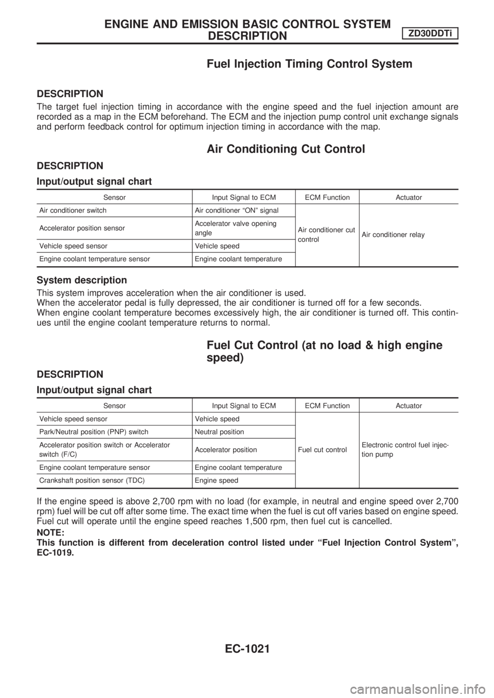
Fuel Injection Timing Control System
DESCRIPTION
The target fuel injection timing in accordance with the engine speed and the fuel injection amount are
recorded as a map in the ECM beforehand. The ECM and the injection pump control unit exchange signals
and perform feedback control for optimum injection timing in accordance with the map.
Air Conditioning Cut Control
DESCRIPTION
Input/output signal chart
Sensor Input Signal to ECM ECM Function Actuator
Air conditioner switch Air conditioner ªONº signal
Air conditioner cut
controlAir conditioner relay Accelerator position sensorAccelerator valve opening
angle
Vehicle speed sensor Vehicle speed
Engine coolant temperature sensor Engine coolant temperature
System description
This system improves acceleration when the air conditioner is used.
When the accelerator pedal is fully depressed, the air conditioner is turned off for a few seconds.
When engine coolant temperature becomes excessively high, the air conditioner is turned off. This contin-
ues until the engine coolant temperature returns to normal.
Fuel Cut Control (at no load & high engine
speed)
DESCRIPTION
Input/output signal chart
Sensor Input Signal to ECM ECM Function Actuator
Vehicle speed sensor Vehicle speed
Fuel cut controlElectronic control fuel injec-
tion pump Park/Neutral position (PNP) switch Neutral position
Accelerator position switch or Accelerator
switch (F/C)Accelerator position
Engine coolant temperature sensor Engine coolant temperature
Crankshaft position sensor (TDC) Engine speed
If the engine speed is above 2,700 rpm with no load (for example, in neutral and engine speed over 2,700
rpm) fuel will be cut off after some time. The exact time when the fuel is cut off varies based on engine speed.
Fuel cut will operate until the engine speed reaches 1,500 rpm, then fuel cut is cancelled.
NOTE:
This function is different from deceleration control listed under ªFuel Injection Control Systemº,
EC-1019.
ENGINE AND EMISSION BASIC CONTROL SYSTEM
DESCRIPTIONZD30DDTi
EC-1021
Page 265 of 1033
DTC and MI Detection Logic
When a malfunction is detected, the malfunction (DTC) is stored in the ECM memory.
The MI will light up each time the ECM detects malfunction. For diagnostic items causing the MI to light up,
refer to ªTROUBLE DIAGNOSIS Ð INDEXº, EC-1006.
Diagnostic Trouble Code (DTC)
HOW TO READ DTC
The DTC can be read by the following methods.
Without CONSULT-II
ECM displays the DTC by a set of four digit numbers with MI illumination in the diagnostic test mode II
(Self-diagnostic results). Example: 0102, 0407, 1004, etc.
With CONSULT-II
CONSULT-II displays the DTC in ªSELF-DIAG RESULTSº mode. Examples: ªCRANK POS SEN (TDC)º, etc.
+Output of the trouble code means that the indicated circuit has a malfunction. However, in the
Mode II it does not indicate whether the malfunction is still occurring or occurred in the past and
returned to normal.
CONSULT-II can identify them. Therefore, using CONSULT-II (if available) is recommended.
HOW TO ERASE DTC
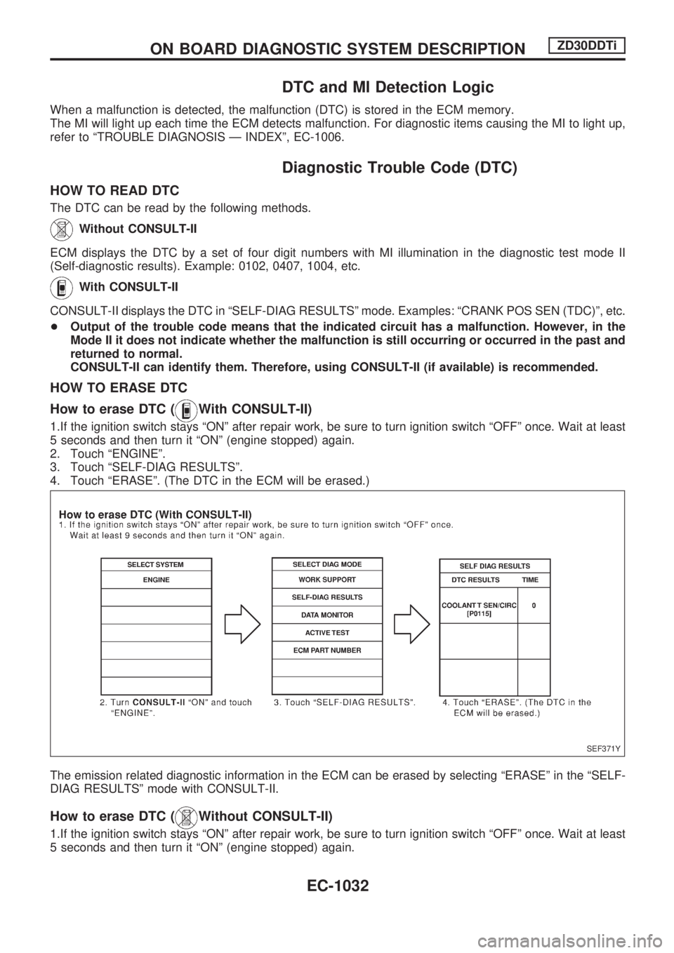
How to erase DTC (
With CONSULT-II)
1.If the ignition switch stays ªONº after repair work, be sure to turn ignition switch ªOFFº once. Wait at least
5 seconds and then turn it ªONº (engine stopped) again.
2. Touch ªENGINEº.
3. Touch ªSELF-DIAG RESULTSº.
4. Touch ªERASEº. (The DTC in the ECM will be erased.)
The emission related diagnostic information in the ECM can be erased by selecting ªERASEº in the ªSELF-
DIAG RESULTSº mode with CONSULT-II.
How to erase DTC (Without CONSULT-II)
1.If the ignition switch stays ªONº after repair work, be sure to turn ignition switch ªOFFº once. Wait at least
5 seconds and then turn it ªONº (engine stopped) again.
SEF371Y
ON BOARD DIAGNOSTIC SYSTEM DESCRIPTIONZD30DDTi
EC-1032
Page 266 of 1033
2. Change the diagnostic test mode from Mode II to Mode I by using the data link connector. (See
EC-1035.)
The emission related diagnostic information in the ECM can be erased by changing the diagnostic test mode.
+If the battery is disconnected, the emission-related diagnostic information will be lost after
approx. 24 hours.
+Erasing the emission-related diagnostic information using CONSULT-II is easier and quicker than
switching the diagnostic test mode using the data link connector.
NATS (Nissan Anti-Theft System)
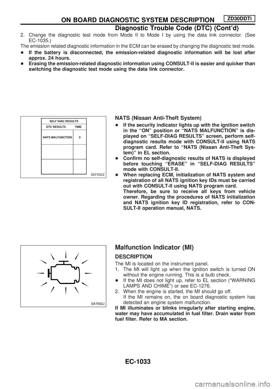
+If the security indicator lights up with the ignition switch
in the ªONº position or ªNATS MALFUNCTIONº is dis-
played on ªSELF-DIAG RESULTSº screen, perform self-
diagnostic results mode with CONSULT-II using NATS
program card. Refer to ªNATS (Nissan Anti-Theft Sys-
tem)º in EL section.
+Confirm no self-diagnostic results of NATS is displayed
before touching ªERASEº in ªSELF-DIAG RESULTSº
mode with CONSULT-II.
+When replacing ECM, initialization of NATS system and
registration of all NATS ignition key IDs must be carried
out with CONSULT-II using NATS program card.
Therefore, be sure to receive all keys from vehicle
owner. Regarding the procedures of NATS initialization
and NATS ignition key ID registration, refer to CON-
SULT-II operation manual, NATS.
Malfunction Indicator (MI)
DESCRIPTION
The MI is located on the instrument panel.
1. The MI will light up when the ignition switch is turned ON
without the engine running. This is a bulb check.
+If the MI does not light up, refer to EL section (ªWARNING
LAMPS AND CHIMEº) or see EC-1276.
2. When the engine is started, the MI should go off.
If the MI remains on, the on board diagnostic system has
detected an engine system malfunction.
If MI illuminates or blinks irregularly after starting engine,
water may have accumulated in fuel filter. Drain water from
fuel filter. Refer to MA section.
SEF252Z
SAT652J
ON BOARD DIAGNOSTIC SYSTEM DESCRIPTIONZD30DDTi
Diagnostic Trouble Code (DTC) (Cont'd)
EC-1033
Page 267 of 1033
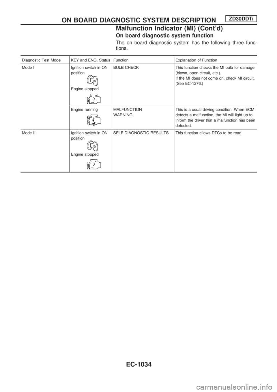
On board diagnostic system function
The on board diagnostic system has the following three func-
tions.
Diagnostic Test Mode KEY and ENG. Status Function Explanation of Function
Mode I Ignition switch in ON
position
Engine stopped
BULB CHECK This function checks the MI bulb for damage
(blown, open circuit, etc.).
If the MI does not come on, check MI circuit.
(See EC-1276.)
Engine running
MALFUNCTION
WARNINGThis is a usual driving condition. When ECM
detects a malfunction, the MI will light up to
inform the driver that a malfunction has been
detected.
Mode II Ignition switch in ON
position
Engine stopped
SELF-DIAGNOSTIC RESULTS This function allows DTCs to be read.
ON BOARD DIAGNOSTIC SYSTEM DESCRIPTIONZD30DDTi
Malfunction Indicator (MI) (Cont'd)
EC-1034
Page 269 of 1033
Diagnostic test mode I Ð Bulb check
In this mode, the MI on the instrument panel should stay ON. If it remains OFF, check the bulb. Refer to EL
section, ªWARNING LAMPS AND CHIMEº or see EC-1276.
Diagnostic test mode I Ð Malfunction warning
MI Condition
ON When the malfunction is detected or the ECM's CPU is malfunctioning.
OFF No malfunction.
Diagnostic test mode II Ð Self-diagnostic results
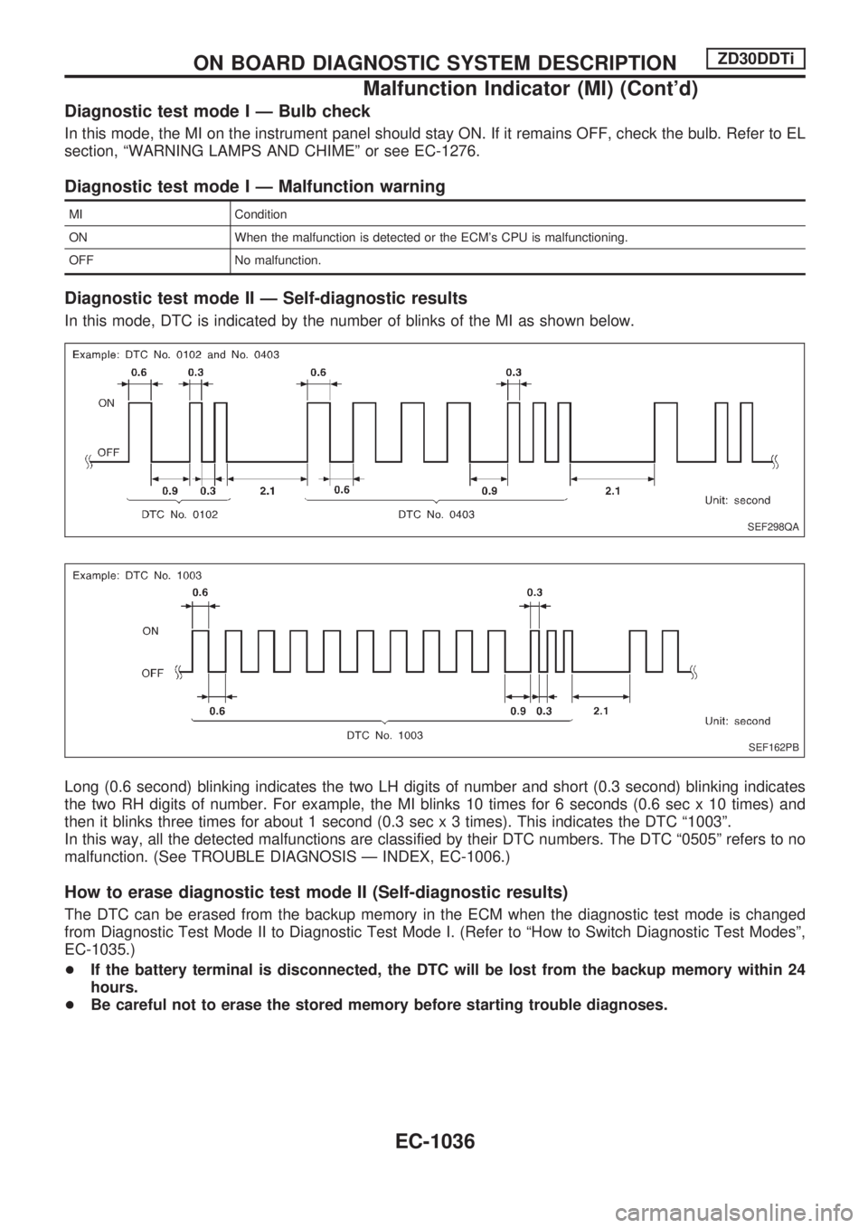
In this mode, DTC is indicated by the number of blinks of the MI as shown below.
Long (0.6 second) blinking indicates the two LH digits of number and short (0.3 second) blinking indicates
the two RH digits of number. For example, the MI blinks 10 times for 6 seconds (0.6 sec x 10 times) and
then it blinks three times for about 1 second (0.3 sec x 3 times). This indicates the DTC ª1003º.
In this way, all the detected malfunctions are classified by their DTC numbers. The DTC ª0505º refers to no
malfunction. (See TROUBLE DIAGNOSIS Ð INDEX, EC-1006.)
How to erase diagnostic test mode II (Self-diagnostic results)
The DTC can be erased from the backup memory in the ECM when the diagnostic test mode is changed
from Diagnostic Test Mode II to Diagnostic Test Mode I. (Refer to ªHow to Switch Diagnostic Test Modesº,
EC-1035.)
+If the battery terminal is disconnected, the DTC will be lost from the backup memory within 24
hours.
+Be careful not to erase the stored memory before starting trouble diagnoses.
SEF298QA
SEF162PB
ON BOARD DIAGNOSTIC SYSTEM DESCRIPTIONZD30DDTi
Malfunction Indicator (MI) (Cont'd)
EC-1036