Page 315 of 1033
7 CHECK ECM POWER SUPPLY CIRCUIT-III
1. Disconnect ECM relay.
SEF225Z
2. Check voltage between relay terminals 1, 3 and ground with CONSULT-II or tester.
SEF289Z
OK or NG
OKcGO TO 9.
NGcGO TO 8.
8 DETECT MALFUNCTIONING PART
Check the following.
+Harness connectors E104, M86 or E127, M21
+20A fuse
+Harness for open or short between ECM relay and battery
cRepair open circuit or short to ground or short to power in harness or connectors.
9 CHECK OUTPUT SIGNAL CIRCUIT FOR OPEN AND SHORT
1. Disconnect ECM harness connector.
2. Check harness continuity between ECM terminal 4 and ECM relay terminal 2. Refer to Wiring Diagram.
Continuity should exist.
3. Also check harness for short to ground and short to power.
OK or NG
OKcGO TO 11.
NGcGO TO 10.
TROUBLE DIAGNOSIS FOR POWER SUPPLYZD30DDTi
Main Power Supply and Ground Circuit
(Cont'd)
EC-1082
Page 316 of 1033

10 DETECT MALFUNCTIONING PART
Check the following.
+Harness connectors M52, F7
+Harness for open or short between ECM and ECM relay
cRepair open circuit or short to ground or short to power in harness or connectors.
11 CHECK ECM POWER SUPPLY CIRCUIT-IV
1. Check harness continuity between ECM terminals 56, 61, 116 and ECM relay terminal 5. Refer to Wiring Diagram.
Continuity should exist.
2. Also check harness for short to ground and short to power.
OK or NG
OKcGO TO 13.
NGcGO TO 12.
12 DETECT MALFUNCTIONING PART
Check the following.
+Harness connectors M50, F5
+Harness for open or short between ECM and ECM relay
cRepair open circuit or short to ground or short to power in harness or connectors.
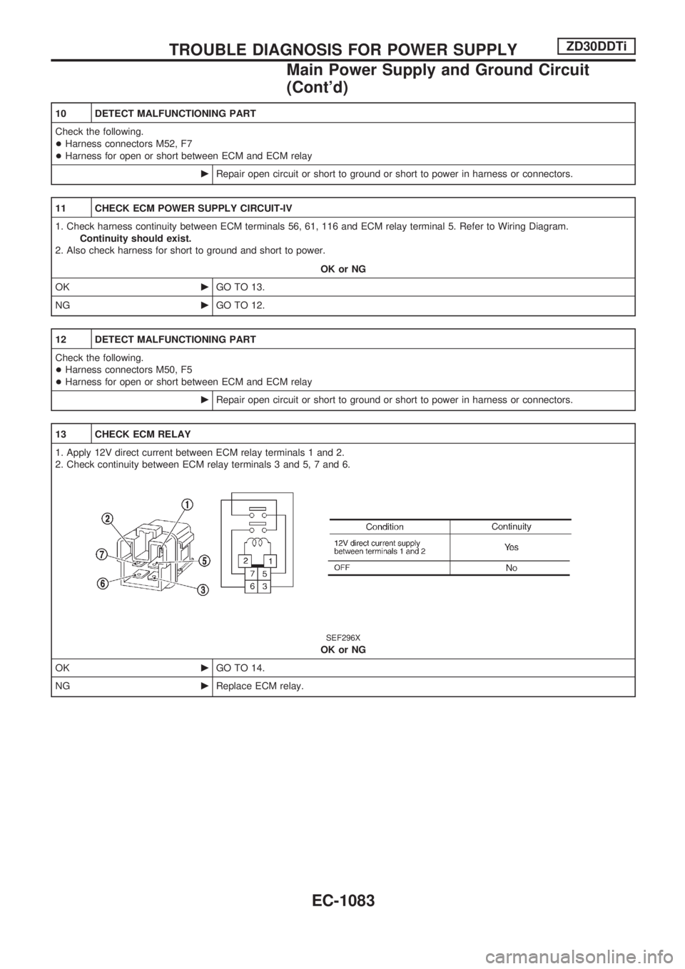
13 CHECK ECM RELAY
1. Apply 12V direct current between ECM relay terminals 1 and 2.
2. Check continuity between ECM relay terminals 3 and 5, 7 and 6.
SEF296X
OK or NG
OKcGO TO 14.
NGcReplace ECM relay.
TROUBLE DIAGNOSIS FOR POWER SUPPLYZD30DDTi
Main Power Supply and Ground Circuit
(Cont'd)
EC-1083
Page 317 of 1033
14 CHECK ECM POWER SUPPLY CIRCUIT-V
1. Reconnect all harness connectors disconnected.
2. Turn ignition switch ªONº.
3. Check voltage between ECM terminal 102 and ground with CONSULT-II or tester.
SEF290Z
OK or NG
OKcGO TO 16.
NGcGO TO 15.
15 DETECT MALFUNCTIONING PART
Check the following.
+Harness connectors M52, F7
+Fuse block (J/B) connector M2
+10A fuse
+Harness for open or short between ECM and fuse
cRepair open circuit or short to ground or short to power in harness or connectors.
16 CHECK ECM POWER SUPPLY CIRCUIT-VI
1. Turn ignition switch ªOFFº.
2. Disconnect ECM relay.
SEF225Z
3. Disconnect ECM harness connector.
4. Check harness continuity between ECM terminals 56, 61, 116 and ECM relay terminal 5. Refer to Wiring Diagram.
Continuity should exist.
5. Also check harness for short to ground and short to power.
OK or NG
OKcGO TO 18.
NGcGO TO 17.
TROUBLE DIAGNOSIS FOR POWER SUPPLYZD30DDTi
Main Power Supply and Ground Circuit
(Cont'd)
EC-1084
Page 318 of 1033
17 DETECT MALFUNCTIONING PART
Check the following.
+Harness connectors M50, F5
+Harness for open or short between ECM and ECM relay
cRepair open circuit or short to ground or short to power in harness or connectors.
18 CHECK ECM GROUND CIRCUIT FOR OPEN AND SHORT
1. Check harness continuity between ECM terminals 39, 43, 106, 112, 118 and engine ground. Refer to Wiring Diagram.
Continuity should exist.
2. Also check harness for short to ground and short to power.
OK or NG
OKcGO TO 20.
NGcGO TO 19.
19 DETECT MALFUNCTIONING PART
Check the following.
+Joint connector-3
+Harness for open or short between ECM and engine ground
cRepair open circuit or short to ground or short to power in harness or connectors.
20 CHECK INTERMITTENT INCIDENT
Refer to ªTROUBLE DIAGNOSIS FOR INTERMITTENT INCIDENTº, EC-1076.
cINSPECTION END
TROUBLE DIAGNOSIS FOR POWER SUPPLYZD30DDTi
Main Power Supply and Ground Circuit
(Cont'd)
EC-1085
Page 319 of 1033

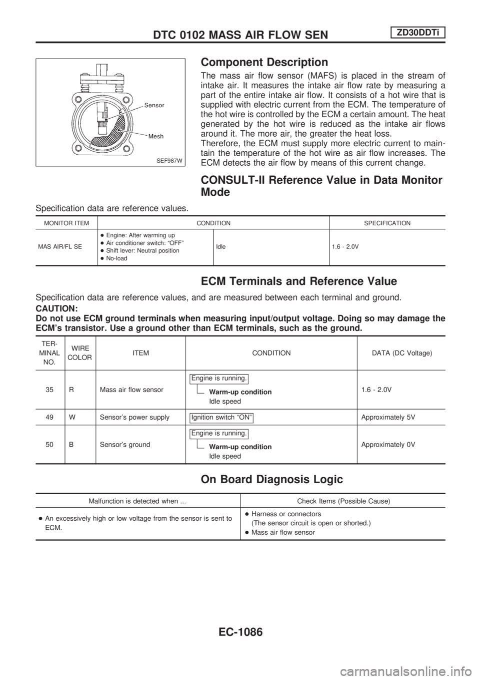
Component Description
The mass air flow sensor (MAFS) is placed in the stream of
intake air. It measures the intake air flow rate by measuring a
part of the entire intake air flow. It consists of a hot wire that is
supplied with electric current from the ECM. The temperature of
the hot wire is controlled by the ECM a certain amount. The heat
generated by the hot wire is reduced as the intake air flows
around it. The more air, the greater the heat loss.
Therefore, the ECM must supply more electric current to main-
tain the temperature of the hot wire as air flow increases. The
ECM detects the air flow by means of this current change.
CONSULT-II Reference Value in Data Monitor
Mode
Specification data are reference values.
MONITOR ITEM CONDITION SPECIFICATION
MAS AIR/FL SE+Engine: After warming up
+Air conditioner switch: ªOFFº
+Shift lever: Neutral position
+No-loadIdle 1.6 - 2.0V
ECM Terminals and Reference Value
Specification data are reference values, and are measured between each terminal and ground.
CAUTION:
Do not use ECM ground terminals when measuring input/output voltage. Doing so may damage the
ECM's transistor. Use a ground other than ECM terminals, such as the ground.
TER-
MINAL
NO.WIRE
COLORITEM CONDITION DATA (DC Voltage)
35 R Mass air flow sensorEngine is running.
Warm-up condition
Idle speed1.6 - 2.0V
49 W Sensor's power supply Ignition switch ªONº
Approximately 5V
50 B Sensor's groundEngine is running.
Warm-up condition
Idle speedApproximately 0V
On Board Diagnosis Logic
Malfunction is detected when ... Check Items (Possible Cause)
+An excessively high or low voltage from the sensor is sent to
ECM.+Harness or connectors
(The sensor circuit is open or shorted.)
+Mass air flow sensor
SEF987W
DTC 0102 MASS AIR FLOW SENZD30DDTi
EC-1086
Page 320 of 1033
DTC Confirmation Procedure
WITH CONSULT-II
1) Turn ignition switch ªONº, and wait at least 6 seconds.
2) Select ªDATA MONITORº mode with CONSULT-II.
3) Start engine and wait at least 3 seconds.
4) If DTC is detected, go to ªDiagnostic Procedureº, EC-1089.
WITHOUT CONSULT-II
1) Turn ignition switch ªONº, and wait at least 6 seconds.
2) Start engine and wait at least 3 seconds.
3) Turn ignition switch ªOFFº, wait at least 5 seconds and then
turn ªONº.
4) Perform ªDiagnostic Test Mode II (Self-diagnostic results)º
with ECM.
5) If DTC is detected, go to ªDiagnostic Procedureº, EC-1089.
SEF817Y
DTC 0102 MASS AIR FLOW SENZD30DDTi
EC-1087
Page 322 of 1033
Diagnostic Procedure
1 CHECK MAFS POWER SUPPLY CIRCUIT
1. Turn ignition switch ªOFFº.
2. Disconnect mass air flow sensor harness connector.
SEF226Z
3. Turn ignition switch ªONº.
4. Check voltage between mass air flow sensor terminals 2, 4 and gund with CONSULT-II or tester.
SEF297X
OK or NG
OKcGO TO 3.
NGcGO TO 2.
2 DETECT MALFUNCTIONING PART
Check the following.
+Harness connectors E230, F12
+Harness connectors M50, F5
+Harness for open or short between mass air flow sensor and ECM
+Harness for open or short between mass air flow sensor and ECM relay
cRepair open circuit or short to ground or short to power in harness or connector.
DTC 0102 MASS AIR FLOW SENZD30DDTi
EC-1089
Page 323 of 1033

3 CHECK MAFS GROUND CIRCUIT FOR OPEN AND SHORT
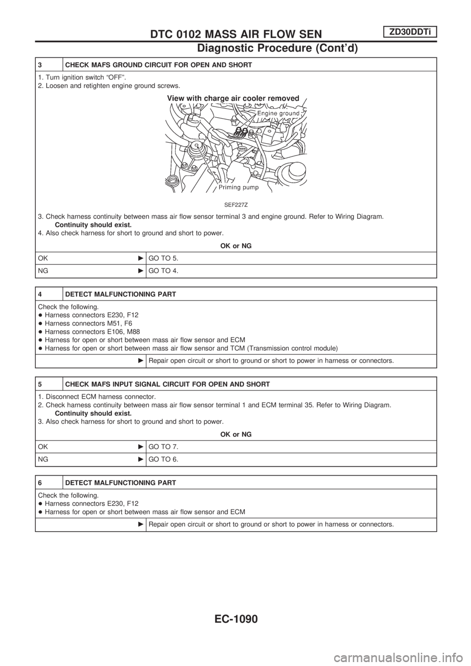
1. Turn ignition switch ªOFFº.
2. Loosen and retighten engine ground screws.
SEF227Z
3. Check harness continuity between mass air flow sensor terminal 3 and engine ground. Refer to Wiring Diagram.
Continuity should exist.
4. Also check harness for short to ground and short to power.
OK or NG
OKcGO TO 5.
NGcGO TO 4.
4 DETECT MALFUNCTIONING PART
Check the following.
+Harness connectors E230, F12
+Harness connectors M51, F6
+Harness connectors E106, M88
+Harness for open or short between mass air flow sensor and ECM
+Harness for open or short between mass air flow sensor and TCM (Transmission control module)
cRepair open circuit or short to ground or short to power in harness or connectors.
5 CHECK MAFS INPUT SIGNAL CIRCUIT FOR OPEN AND SHORT
1. Disconnect ECM harness connector.
2. Check harness continuity between mass air flow sensor terminal 1 and ECM terminal 35. Refer to Wiring Diagram.
Continuity should exist.
3. Also check harness for short to ground and short to power.
OK or NG
OKcGO TO 7.
NGcGO TO 6.
6 DETECT MALFUNCTIONING PART
Check the following.
+Harness connectors E230, F12
+Harness for open or short between mass air flow sensor and ECM
cRepair open circuit or short to ground or short to power in harness or connectors.
DTC 0102 MASS AIR FLOW SENZD30DDTi
Diagnostic Procedure (Cont'd)
EC-1090