Page 117 of 1033
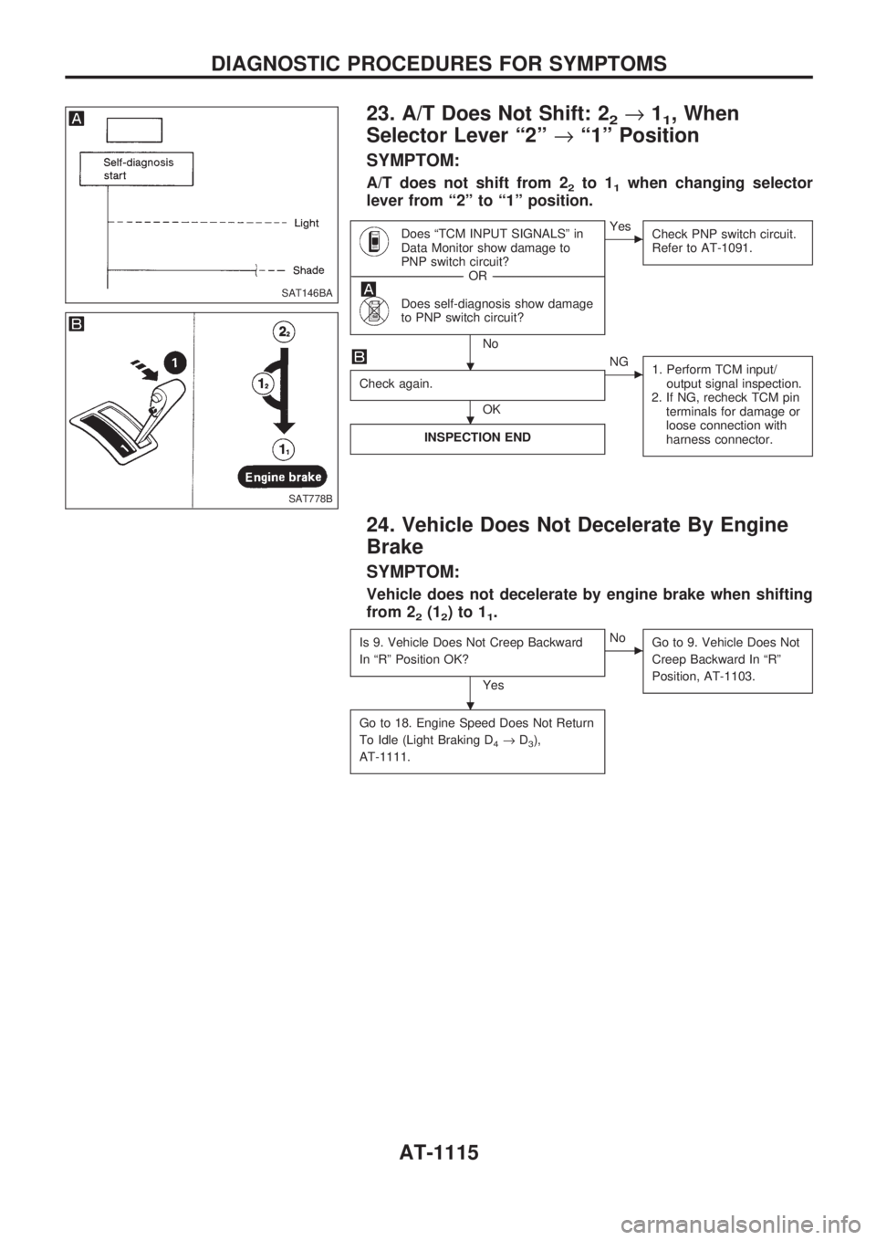
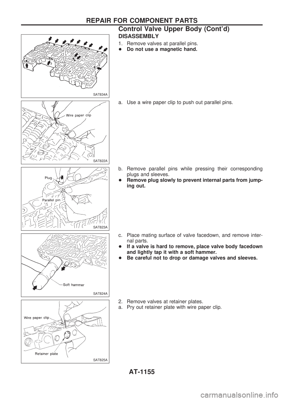
23. A/T Does Not Shift: 22®11, When
Selector Lever ª2º®ª1º Position
SYMPTOM:
A/T does not shift from 22to 11when changing selector
lever from ª2º to ª1º position.
Does ªTCM INPUT SIGNALSº in
Data Monitor show damage to
PNP switch circuit?
------------------------------------------------------------------------------------------------------------------------------------OR------------------------------------------------------------------------------------------------------------------------------------
Does self-diagnosis show damage
to PNP switch circuit?
No
cYes
Check PNP switch circuit.
Refer to AT-1091.
Check again.
OK
cNG
1. Perform TCM input/
output signal inspection.
2. If NG, recheck TCM pin
terminals for damage or
loose connection with
harness connector.
INSPECTION END
24. Vehicle Does Not Decelerate By Engine
Brake
SYMPTOM:
Vehicle does not decelerate by engine brake when shifting
from 2
2(12)to11.
Is 9. Vehicle Does Not Creep Backward
In ªRº Position OK?
Yes
cNo
Go to 9. Vehicle Does Not
Creep Backward In ªRº
Position, AT-1103.
Go to 18. Engine Speed Does Not Return
To Idle (Light Braking D
4®D3),
AT-1111.
SAT146BA
SAT778B
.
.
.
DIAGNOSTIC PROCEDURES FOR SYMPTOMS
AT-1115
Page 130 of 1033
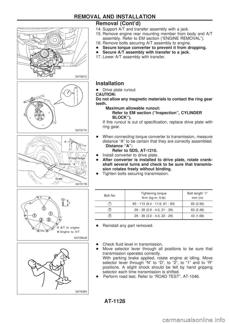
14. Support A/T and transfer assembly with a jack.
15. Remove engine rear mounting member from body and A/T
assembly. Refer to EM section (ªENGINE REMOVALº).
16. Remove bolts securing A/T assembly to engine.
+Secure torque converter to prevent it from dropping.
+Secure A/T assembly with transfer to a jack.
17. Lower A/T assembly with transfer.
Installation
+Drive plate runout
CAUTION:
Do not allow any magnetic materials to contact the ring gear
teeth.
Maximum allowable runout:
Refer to EM section (ªInspectionº, CYLINDER
BLOCKº).
If this runout is out of specification, replace drive plate with
ring gear.
+When connecting torque converter to transmission, measure
distance ªAº to be certain that they are correctly assembled.
Distance ªAº:
Refer to SDS, AT-1210.
+Install converter to drive plate.
+After converter is installed to drive plate, rotate crank-
shaft several turns and check to be sure that transmis-
sion rotates freely without binding.
+Tighten bolts securing transmission.
Bolt No.Tightening torque
Nzm (kg-m, ft-lb)Bolt length ª!º
mm (in)
V183 - 113 (8.4 - 11.6, 61 - 83) 65 (2.56)
V229 - 39 (2.9 - 4.0, 21 - 28) 63 (2.48)
V329 - 39 (3.0 - 4.0, 22 - 29) 43 (1.69)
+Reinstall any part removed.
+Check fluid level in transmission.
+Move selector lever through all positions to be sure that
transmission operates correctly.
With parking brake applied, rotate engine at idling. Move
selector lever through ªNº to ªDº, to ª2º, to ª1º and to ªRº
positions. A slight shock should be felt by hand gripping
selector each time transmission is shifted.
+Perform road test. Refer to ªROAD TESTº, AT-1046.
SAT801C
SAT977H
SAT017B
SAT266JB
SAT638A
REMOVAL AND INSTALLATION
Removal (Cont'd)
AT-1128
Page 157 of 1033
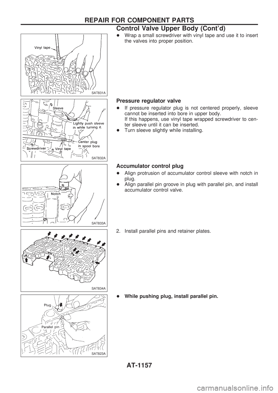
DISASSEMBLY
1. Remove valves at parallel pins.
+Do not use a magnetic hand.
a. Use a wire paper clip to push out parallel pins.
b. Remove parallel pins while pressing their corresponding
plugs and sleeves.
+Remove plug slowly to prevent internal parts from jump-
ing out.
c. Place mating surface of valve facedown, and remove inter-
nal parts.
+If a valve is hard to remove, place valve body facedown
and lightly tap it with a soft hammer.
+Be careful not to drop or damage valves and sleeves.
2. Remove valves at retainer plates.
a. Pry out retainer plate with wire paper clip.
SAT834A
SAT822A
SAT823A
SAT824A
SAT825A
REPAIR FOR COMPONENT PARTS
Control Valve Upper Body (Cont'd)
AT-1155
Page 158 of 1033
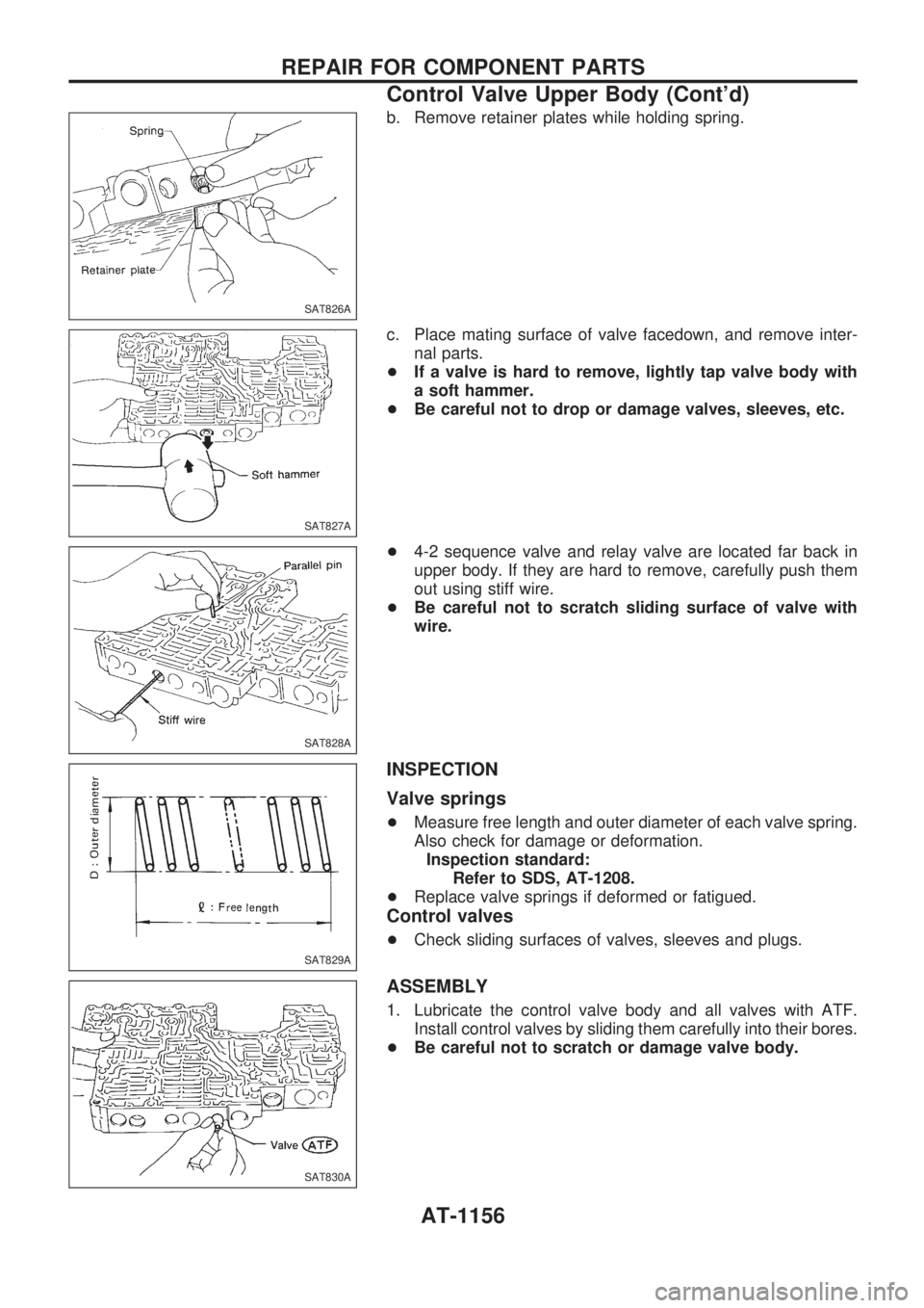
b. Remove retainer plates while holding spring.
c. Place mating surface of valve facedown, and remove inter-
nal parts.
+If a valve is hard to remove, lightly tap valve body with
a soft hammer.
+Be careful not to drop or damage valves, sleeves, etc.
+4-2 sequence valve and relay valve are located far back in
upper body. If they are hard to remove, carefully push them
out using stiff wire.
+Be careful not to scratch sliding surface of valve with
wire.
INSPECTION
Valve springs
+Measure free length and outer diameter of each valve spring.
Also check for damage or deformation.
Inspection standard:
Refer to SDS, AT-1208.
+Replace valve springs if deformed or fatigued.
Control valves
+Check sliding surfaces of valves, sleeves and plugs.
ASSEMBLY
1. Lubricate the control valve body and all valves with ATF.
Install control valves by sliding them carefully into their bores.
+Be careful not to scratch or damage valve body.
SAT826A
SAT827A
SAT828A
SAT829A
SAT830A
REPAIR FOR COMPONENT PARTS
Control Valve Upper Body (Cont'd)
AT-1156
Page 159 of 1033
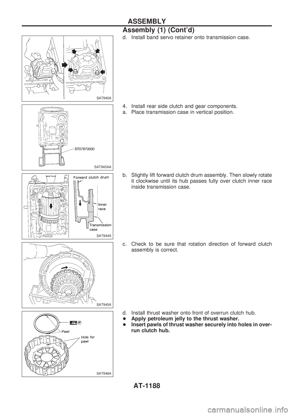
+Wrap a small screwdriver with vinyl tape and use it to insert
the valves into proper position.
Pressure regulator valve
+If pressure regulator plug is not centered properly, sleeve
cannot be inserted into bore in upper body.
If this happens, use vinyl tape wrapped screwdriver to cen-
ter sleeve until it can be inserted.
+Turn sleeve slightly while installing.
Accumulator control plug
+Align protrusion of accumulator control sleeve with notch in
plug.
+Align parallel pin groove in plug with parallel pin, and install
accumulator control valve.
2. Install parallel pins and retainer plates.
+While pushing plug, install parallel pin.
SAT831A
SAT832A
SAT833A
SAT834A
SAT823A
REPAIR FOR COMPONENT PARTS
Control Valve Upper Body (Cont'd)
AT-1157
Page 190 of 1033
d. Install band servo retainer onto transmission case.
4. Install rear side clutch and gear components.
a. Place transmission case in vertical position.
b. Slightly lift forward clutch drum assembly. Then slowly rotate
it clockwise until its hub passes fully over clutch inner race
inside transmission case.
c. Check to be sure that rotation direction of forward clutch
assembly is correct.
d. Install thrust washer onto front of overrun clutch hub.
+Apply petroleum jelly to the thrust washer.
+Insert pawls of thrust washer securely into holes in over-
run clutch hub.
SAT940A
SAT943AA
SAT944A
SAT945A
SAT946A
ASSEMBLY
Assembly (1) (Cont'd)
AT-1188
Page 197 of 1033
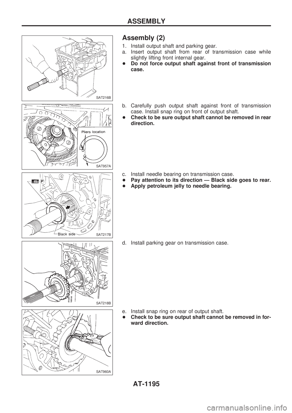
Assembly (2)
1. Install output shaft and parking gear.
a. Insert output shaft from rear of transmission case while
slightly lifting front internal gear.
+Do not force output shaft against front of transmission
case.
b. Carefully push output shaft against front of transmission
case. Install snap ring on front of output shaft.
+Check to be sure output shaft cannot be removed in rear
direction.
c. Install needle bearing on transmission case.
+Pay attention to its direction Ð Black side goes to rear.
+Apply petroleum jelly to needle bearing.
d. Install parking gear on transmission case.
e. Install snap ring on rear of output shaft.
+Check to be sure output shaft cannot be removed in for-
ward direction.
SAT216B
SAT957A
SAT217B
SAT218B
SAT960A
ASSEMBLY
AT-1195
Page 220 of 1033
Self-diagnosis
FUNCTION
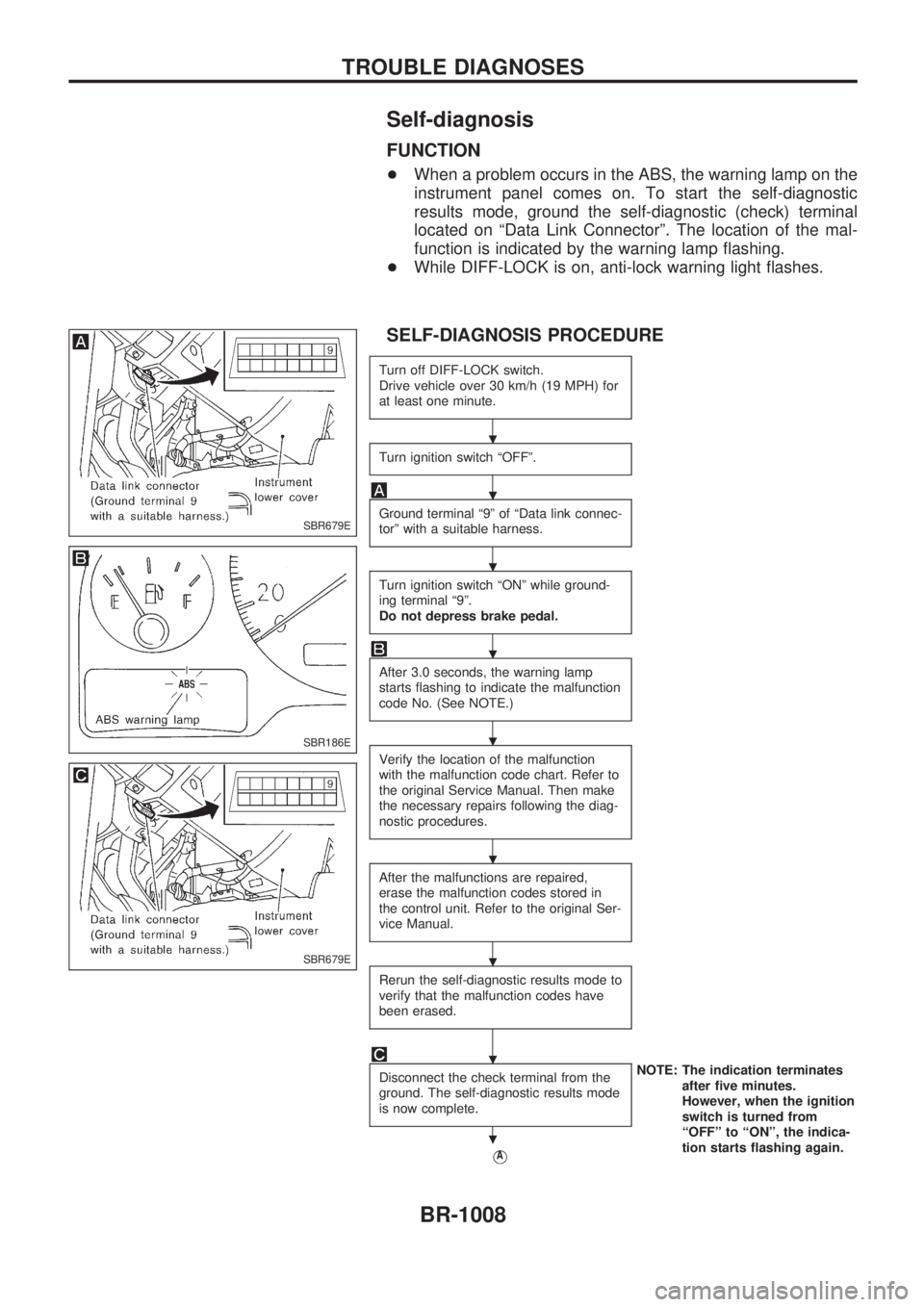
+When a problem occurs in the ABS, the warning lamp on the
instrument panel comes on. To start the self-diagnostic
results mode, ground the self-diagnostic (check) terminal
located on ªData Link Connectorº. The location of the mal-
function is indicated by the warning lamp flashing.
+While DIFF-LOCK is on, anti-lock warning light flashes.
SELF-DIAGNOSIS PROCEDURE
Turn off DIFF-LOCK switch.
Drive vehicle over 30 km/h (19 MPH) for
at least one minute.
Turn ignition switch ªOFFº.
Ground terminal ª9º of ªData link connec-
torº with a suitable harness.
Turn ignition switch ªONº while ground-
ing terminal ª9º.
Do not depress brake pedal.
After 3.0 seconds, the warning lamp
starts flashing to indicate the malfunction
code No. (See NOTE.)
Verify the location of the malfunction
with the malfunction code chart. Refer to
the original Service Manual. Then make
the necessary repairs following the diag-
nostic procedures.
After the malfunctions are repaired,
erase the malfunction codes stored in
the control unit. Refer to the original Ser-
vice Manual.
Rerun the self-diagnostic results mode to
verify that the malfunction codes have
been erased.
Disconnect the check terminal from the
ground. The self-diagnostic results mode
is now complete.NOTE: The indication terminates
after five minutes.
However, when the ignition
switch is turned from
ªOFFº to ªONº, the indica-
tion starts flashing again.
VA
SBR679E
SBR186E
SBR679E
.
.
.
.
.
.
.
.
.
TROUBLE DIAGNOSES
BR-1008