Page 358 of 1033
Description
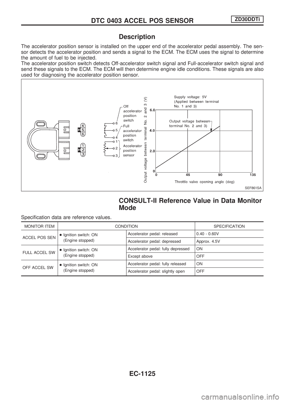
The accelerator position sensor is installed on the upper end of the accelerator pedal assembly. The sen-
sor detects the accelerator position and sends a signal to the ECM. The ECM uses the signal to determine
the amount of fuel to be injected.
The accelerator position switch detects Off-accelerator switch signal and Full-accelerator switch signal and
send these signals to the ECM. The ECM will then determine engine idle conditions. These signals are also
used for diagnosing the accelerator position sensor.
CONSULT-II Reference Value in Data Monitor
Mode
Specification data are reference values.
MONITOR ITEM CONDITION SPECIFICATION
ACCEL POS SEN+Ignition switch: ON
(Engine stopped)Accelerator pedal: released 0.40 - 0.60V
Accelerator pedal: depressed Approx. 4.5V
FULL ACCEL SW+Ignition switch: ON
(Engine stopped)Accelerator pedal: fully depressed ON
Except above OFF
OFF ACCEL SW+Ignition switch: ON
(Engine stopped)Accelerator pedal: fully released ON
Accelerator pedal: slightly open OFF
SEF861SA
DTC 0403 ACCEL POS SENSORZD30DDTi
EC-1125
Page 511 of 1033
ELECTRICAL SYSTEM
SECTION
EL
When you read wiring diagrams:
+Read GI section, ªHOW TO READ WIRING DIAGRAMSº.
When you perform trouble diagnoses, read GI section, ªHOW TO FOLLOW FLOW
CHART IN TROUBLE DIAGNOSESº and ªHOW TO PERFORM EFFICIENT DIAGNOSIS
FOR AN ELECTRICAL INCIDENTº.
+Check for any service bulletins before servicing the vehicle.
MODIFICATION NOTICE:
+Power window (driver's side only) with an interruption detection function has been adopted.
+ID code entry procedure of multi-remote control system has been changed.
+NATS (Nissan Anti-Theft System) has been adopted on ZD engine model.
CONTENTS
PRECAUTIONS AND PREPARATION............... 1003
Supplemental Restraint System (SRS) ªAIR
BAGº and ªSEAT BELT PRE-TENSIONERº ... 1003
POWER SUPPLY ROUTING............................... 1004
Schematic ........................................................ 1004
Wiring Diagram Ð POWER Ð ........................ 1005
GROUND DISTRIBUTION/LHD MODELS.......... 1013
Engine Room Harness..................................... 1013
Engine Control Harness................................... 1016
Main Harness ................................................... 1017
Body Harness .................................................. 1020
Body No. 2 Harness ........................................ 1022
Back Door and Rear Window Defogger
Harness ............................................................ 1023
GROUND DISTRIBUTION/RHD MODELS......... 1024
Engine Room Harness..................................... 1024
Engine Control Harness................................... 1027
Main Harness ................................................... 1028
Body Harness .................................................. 1031
Body No. 2 Harness ........................................ 1033
Back Door and Rear Window Defogger
Harness ............................................................ 1034
BATTERY............................................................. 1035
Service Data and Specifications (SDS) ........... 1035
STARTING SYSTEM........................................... 1036
Wiring Diagram Ð START Ð/M/T Models...... 1036
Wiring Diagram Ð START Ð/A/T Models ...... 1037
Construction ..................................................... 1038Service Data and Specifications (SDS) ........... 1039
CHARGING SYSTEM.......................................... 1040
Wiring Diagram Ð CHARGE ........................... 1040
Construction ..................................................... 1041
Service Data and Specifications (SDS) ........... 1041
COMBINATION SWITCH.................................... 1042
Check ............................................................... 1042
STEERING SWITCH............................................ 1043
Check ............................................................... 1043
HEADLAMP Ð Daytime Light System Ð........ 1044
Wiring Diagram Ð DTRL Ð ............................ 1044
PARKING, LICENSE AND TAIL LAMPS........... 1046
Wiring Diagram Ð TAIL/L Ð/LHD Models ...... 1046
Wiring Diagram Ð TAIL/L Ð/RHD Models ..... 1048
STOP LAMP........................................................ 1050
Wiring Diagram Ð STOP/L Ð......................... 1050
BACK-UP LAMP.................................................. 1051
Wiring Diagram Ð BACK/L Ð/RHD Models ... 1051
FRONT FOG LAMP............................................. 1052
Wiring Diagram Ð F/FOG Ð .......................... 1052
REAR FOG LAMP............................................... 1053
Wiring Diagram Ð R/FOG Ð .......................... 1053
CORNERING LAMP............................................ 1054
Wiring Diagram Ð CORNER Ð/LHD Models . 1054
System Description/RHD Models .................... 1055
Wiring Diagram Ð CORNER Ð/RHD Models1056
Trouble Diagnoses/RHD Models ..................... 1057
EL
Page 554 of 1033
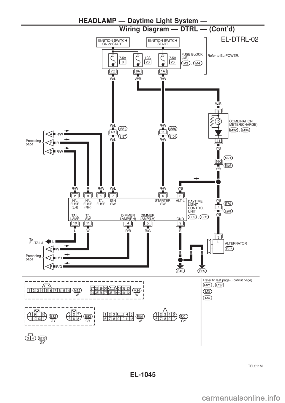
Wiring Diagram Ð DTRL Ð
TEL675B
HEADLAMP Ð Daytime Light System Ð
EL-1044
Page 555 of 1033
TEL211M
HEADLAMP Ð Daytime Light System Ð
Wiring Diagram Ð DTRL Ð (Cont'd)
EL-1045
Page 565 of 1033
System Description/RHD Models
The cornering lamp operation is controlled by the lighting switch which is built into the combination switch
and cornering lamp relay unit.
Power is supplied at all times
+to lighting switch terminal
V11
+through 10A fuse [No.15, located in the fuse block (J/B)].
Lighting operation by lighting switch
When lighting switch is in 1ST (or 2ND) position, power is supplied
+to cornering lamp relay unit terminal
V3
+through lighting switch terminalV12.
With the ignition switch in the ON or START position, power is supplied to cornering lamp relay unit termi-
nal
V2
+through 7.5A fuse [No.11, located in the fuse block (J/B)].
RH turn
When the turn signal lever is moved to the RH position, ground is supplied
+to cornering lamp relay unit terminal
V6
+through turn signal lamp switch terminalsV2andV1
+through body groundsE25andE40.
Power is supplied
+from terminal
V5of the cornering lamp relay unit
+to front combination lamp RH terminal
V3.
Ground is supplied to terminal
V4of front combination lamp RH through body groundsE25andE40.
The RH cornering lamp illuminates until the turn signal lever returns to NEUTRAL position.
LH turn
When the turn signal lever is moved to the LH position, ground is supplied
+to cornering lamp relay unit terminal
V8
+through turn signal lamp switch terminalsV3andV1
+through body groundsE25andE40.
Power is supplied
+from terminal
V10of the cornering lamp relay unit
+to front combination lamp LH terminal
V3.
Ground is supplied to terminal
V4of front combination lamp LH through body groundsE25andE40.
The LH cornering lamp illuminates until the turn signal lever returns to NEUTRAL position.
CORNERING LAMP
EL-1055
Page 567 of 1033
Trouble Diagnoses/RHD Models
Symptom Possible cause Repair order
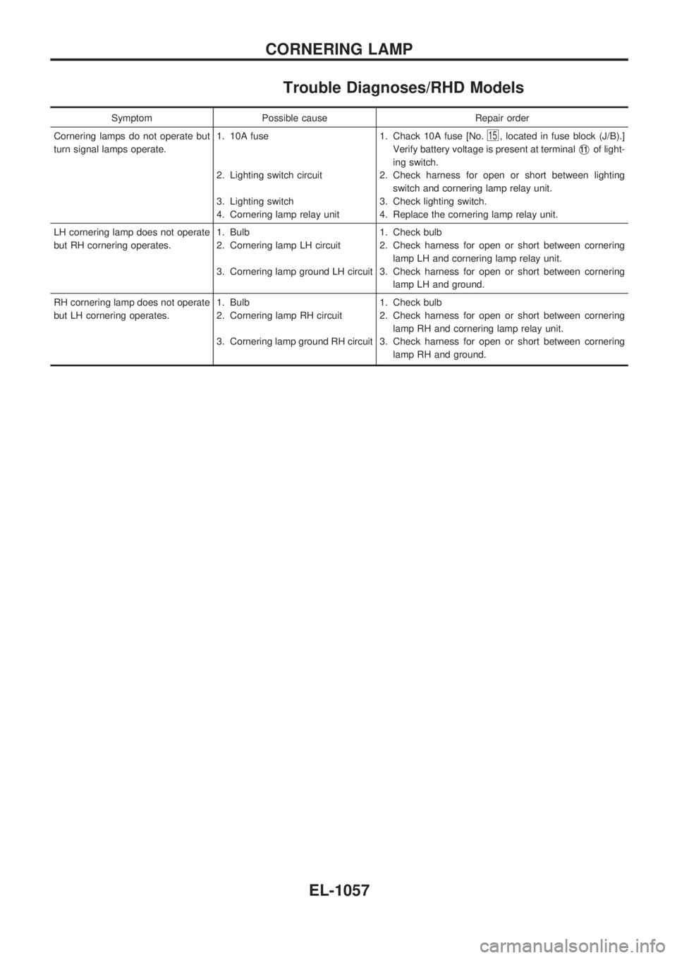
Cornering lamps do not operate but
turn signal lamps operate.1. 10A fuse
2. Lighting switch circuit
3. Lighting switch
4. Cornering lamp relay unit1. Chack 10A fuse [No.
15, located in fuse block (J/B).]
Verify battery voltage is present at terminal
V11of light-
ing switch.
2. Check harness for open or short between lighting
switch and cornering lamp relay unit.
3. Check lighting switch.
4. Replace the cornering lamp relay unit.
LH cornering lamp does not operate
but RH cornering operates.1. Bulb
2. Cornering lamp LH circuit
3. Cornering lamp ground LH circuit1. Check bulb
2. Check harness for open or short between cornering
lamp LH and cornering lamp relay unit.
3. Check harness for open or short between cornering
lamp LH and ground.
RH cornering lamp does not operate
but LH cornering operates.1. Bulb
2. Cornering lamp RH circuit
3. Cornering lamp ground RH circuit1. Check bulb
2. Check harness for open or short between cornering
lamp RH and cornering lamp relay unit.
3. Check harness for open or short between cornering
lamp RH and ground.
CORNERING LAMP
EL-1057
Page 601 of 1033
System Description
The warning chime is combined with the super lock control unit.
Both the ignition key and light warning chime will not sound, when ignition switch in the ON or START posi-
tion (when power supply exists at super lock control unit terminal
V17).
IGNITION KEY WARNING CHIME
With the key in the ignition key cylinder, the ignition switch in the OFF or ACC position, and the driver's door
open and locked, the warning chime will sound. Power is supplied
+from key switch terminal
V1
+to super lock control unit terminalV18.
Ground is supplied
+through driver front door switch terminal
V1
+to super lock control unit terminalV30, and
+through front door lock actuator assembly (driver side) (unlock sensor) terminal
V2
+to super lock control unit terminalV28.
LIGHT WARNING CHIME
With ignition switch in the OFF or ACC position, driver's door open, and lighting switch in 1ST or 2ND
position, warning chime will sound. Power is supplied
+from combination switch terminal
V12
+to super lock control unit terminalV19.
Ground is supplied
+through driver front door switch terminal
V1
+to super lock control unit terminalV30.
WARNING CHIME
EL-1091
Page 604 of 1033
Trouble Diagnoses
SYMPTOM CHART
REFERENCE PAGE EL-1094 EL-1095 EL-1095 EL-1096
SYMPTOM
DIAGNOSTIC PROCEDURE 1
(Lighting switch input signal check)
DIAGNOSTIC PROCEDURE 2
(Key switch input signal check)
DIAGNOSTIC PROCEDURE 3
(Door unlock sensor check)
DIAGNOSTIC PROCEDURE 4
Light warning chime does not acti-
vate.XX
Ignition key warning chime does not
activate.XXX
All warning chimes do not activate.X
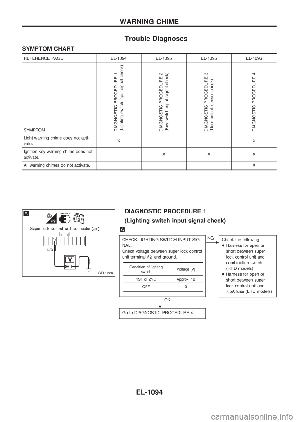
DIAGNOSTIC PROCEDURE 1
(Lighting switch input signal check)
CHECK LIGHTING SWITCH INPUT SIG-
NAL.
Check voltage between super lock control
unit terminal
V19and ground.
OK
cNG
Check the following.
+Harness for open or
short between super
lock control unit and
combination switch
(RHD models)
+Harness for open or
short between super
lock control unit and
7.5A fuse (LHD models)
Go to DIAGNOSTIC PROCEDURE 4.
Condition of lighting
switchVoltage [V]
1ST or 2ND Approx. 12
OFF 0
SEL122X
.
WARNING CHIME
EL-1094