2000 MITSUBISHI MONTERO battery
[x] Cancel search: batteryPage 1217 of 1839

BASIC BRAKE SYSTEM -Troubleshooting35A-9
INSPECTION CHART FOR DIAGNOSIS CODES
Diagnosis
code No.Diagnosis itemsReference page
16*ABS-ECU power supply (Abnormal voltage decrease or increase)35A-9
17, 18ABS-ECU power supply (Open circuit or short circuit)
53Motor relay system (open circuit, short circuit or motor relay coil failure)35A-10
55Pump motor system (Pump motor seized or abnormal ABS-ECU current
detection circuit)35A-11
63ABS-ECU systemReplace ABS-ECU
(Refer to 35B.)
78Accumulator system (Motor has been energized abnormally for long time
or abnormal low-pressure accumulator)35A-12
79Pressure switch system (open circuit or short circuit)35A-13
NOTE
*: Code No. 16 is erased by turning the ignition switch OFF.
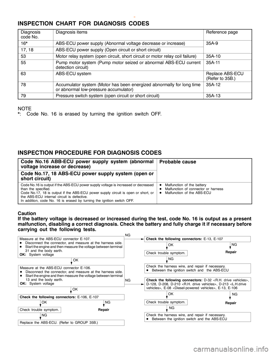
INSPECTION PROCEDURE FOR DIAGNOSIS CODES
Code No.16 ABB-ECU power supply system (abnormal
voltage increase or decrease)Probable cause
Code No.17, 18 ABS-ECU power supply system (open or
short circuit)
Code No.16 is output if the ABS-ECU power supply voltage is increased or decreased
than the specified.
Code No.17, 18 is output if the ABS-ECU power supply circuit isopen orshort, or
the ABS-ECU internal circuit is defective.
In addition, code No. 16 is erased by turning the ignition switch OFF.DMalfunction of the battery
DMalfunction of connector or harness
DMalfunction of the ABS-ECU
Caution
If the battery voltage is decreased or increased during the test, code No. 16 is output as a present
malfunction, disabling a correct diagnosis. Check the battery and fully charge it if necessary before
carrying out the following tests.
NG
NG
OK
NG
Replace the ABS-ECU. (Refer to GROUP 35B.)
OK
Check trouble symptom.
NG
Repair
NG
Check the harness wire, and repair if necessary.
DBetween the ignition switch and the ABS-ECU
OK
Check trouble symptom.
Measure at the ABS-ECU connector E-107.
DDisconnect the connector, and measure at the harness side.
DStart theengine and then measure the voltage between terminal
31 and the body earth.
OK:System voltageNGCheck the following connectors:E-13, E-107
Repair
OK
Check the following connectors:E-106, E-107
NG
Check the harness wire, and repair if necessary.
DBetween the ignition switch and the ABS-ECU
OK
Check trouble symptom.
Measure at the ABS-ECU connector E-106.
DDisconnect the connector, and measure at the harness side.
DStart theengine and then measure the voltage between terminal
13 and the body earth.
OK:System voltageNG
Check the following connectors:D-32
D-128, D-208, D-210
Repair
www.WorkshopManuals.co.uk
Purchased from www.WorkshopManuals.co.uk
Page 1264 of 1839

35B-1
ANTI-SKID
BRAKING SYSTEM
(ABS) <4WD>
CONTENTS
GENERAL INFORMATION 2..................
SERVICE SPECIFICATIONS 4.................
LUBRICANT Refer to GROUP 35A...........
SEALANTS Refer to GROUP 35A............
SPECIAL TOOLS 4..........................
TROUBLESHOOTING 4.......................
ON-VEHICLE SERVICE 27...................
Wheel Speed Sensor Output Voltage
Measurement 27...............................
ABS Valve Relay Continuity Check 28...........
Hydraulic Brake Booster (HBB) - Hydraulic Unit
Check 29......................................
Solenoid Valve Check 30.......................
When the Battery is Flat 31....................
Brake Pedal Check and Adjustment
Refer to GROUP 35A ..........................
Hydraulic Brake Booster (HBB) Operation Check
Refer to GROUP 35A ..........................
Hydraulic Brake Booster (HBB) Check
Refer to GROUP 35A ..........................Motor Relay Continuity Check
Refer to GROUP 35A ..........................
Bleeding Refer to GROUP 35A..................
Brake Fluid Level Sensor Check
Refer to GROUP 35A ..........................
Disc Brake Pad Check and Replacement
Refer to GROUP 35A ..........................
Brake Disc Thickness Check
Refer to GROUP 35A ..........................
Brake Disc Runout Check and Correction
Refer to GROUP 35A ..........................BRAKE PEDAL Refer to GROUP 35A........
HYDRAULIC BRAKE BOOSTER (HBB)
Refer to GROUP 35A ........................
HBB BUZZER Refer to GROUP 35A..........
FRONT DISC BRAKE Refer to GROUP 35A..
REAR DISC BRAKE Refer to GROUP 35A....
ABS-ECU 32................................
WHEEL SPEED SENSOR 33.................
G-SENSOR 36..............................
www.WorkshopManuals.co.uk
Purchased from www.WorkshopManuals.co.uk
Page 1273 of 1839

ABS <4WD> -Troubleshooting35B-10
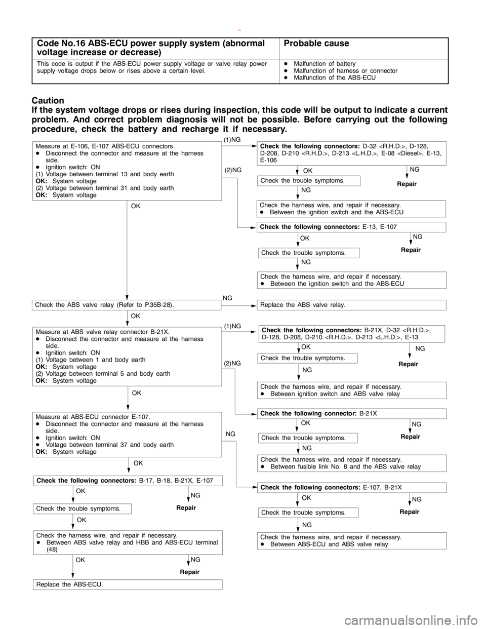
Code No.16 ABS-ECU power supply system (abnormal
voltage increase or decrease)Probable cause
This code is output if the ABS-ECU power supply voltage or valve relay power
supply voltage drops below or rises above a certain level.DMalfunction of battery
DMalfunction of harness or connector
DMalfunction of the ABS-ECU
Caution
If the system voltage drops or rises during inspection, this code will beoutput to indicate a current
problem. And correct problem diagnosis will not be possible. Before carrying out the following
procedure, check the battery and recharge it if necessary.
OKNG
Repair
OK
(1)NGCheck the following connectors:D-32
D-208, D-210
E-106
NG
Check the harness wire, and repair if necessary.
DBetween the ignition switch and the ABS-ECU (2)NG
OK
Check the trouble symptoms.
NG
Repair
NG
Check the harness wire, and repair if necessary.
DBetween the ignition switch and the ABS-ECU
Check the following connectors:E-13, E-107
Measure at E-106, E-107 ABS-ECU connectors.
DDisconnect the connector and measure at the harness
side.
DIgnition switch: ON
(1) Voltage between terminal 13 and body earth
OK:System voltage
(2) Voltage between terminal 31 and body earth
OK:System voltage
NG (1)NG
Check the ABS valve relay (Refer to P.35B-28).NGReplace the ABS valve relay.
OK
Check the harness wire, and repair if necessary.
DBetween ignition switch and ABS valve relay
OK
Repair
OK
Replace the ABS-ECU.
Check the trouble symptoms.
Check the following connectors:B-21X, D-32
D-128, D-208, D-210
NG(2)NG
Check the harness wire, and repair if necessary.
DBetween fusible link No. 8 and the ABS valve relay
OK
NG
Repair
NGCheck the trouble symptoms.
Check the following connector:B-21X
OK
NG
OK
NG
Repair
Check the harness wire, and repair if necessary.
DBetween ABS-ECU and ABS valve relayNG
Check the trouble symptoms.
Check the following connectors:E-107, B-21X
OK
OK
NG
RepairCheck the trouble symptoms.
Check the following connectors:B-17, B-18, B-21X, E-107
NG
Repair
Check the harness wire, and repair if necessary.
DBetween ABS valve relay and HBB and ABS-ECU terminal
(48)
Measure at ABS-ECU connector E-107.
DDisconnect the connector and measure at the harness
side.
DIgnition switch: ON
DVoltage between terminal 37 and body earth
OK:System voltage
Measure at ABS valve relay connector B-21X.
DDisconnect the connector and measure at the harness
side.
DIgnition switch: ON
(1) Voltage between 1 and body earth
OK:System voltage
(2) Voltage between terminal 5 and body earth
OK:System voltage
Check the trouble symptoms.
www.WorkshopManuals.co.uk
Purchased from www.WorkshopManuals.co.uk
Page 1281 of 1839

ABS <4WD> -Troubleshooting35B-18
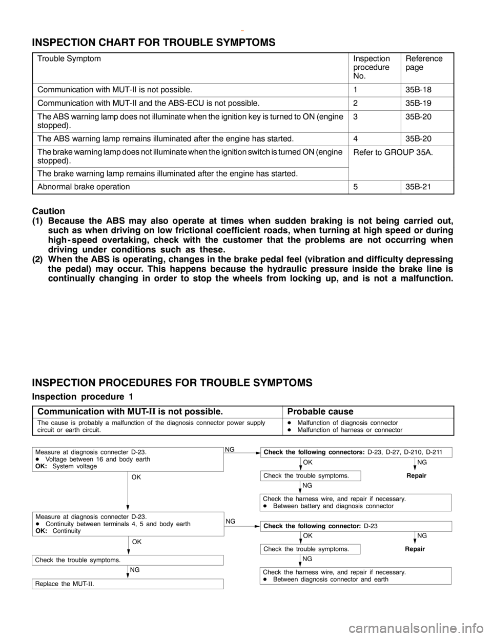
INSPECTION CHART FOR TROUBLE SYMPTOMS
Trouble SymptomInspection
procedure
No.Reference
page
Communication with MUT-II is not possible.135B-18
Communication with MUT-II and the ABS-ECU is not possible.235B-19
The ABS warning lamp does not illuminate when the ignition key is turned to ON (engine
stopped).335B-20
The ABS warning lamp remains illuminated after the engine has started.435B-20
The brake warning lamp does not illuminate when the ignition switch is turned ON (engine
stopped).Refer to GROUP 35A.
The brake warning lamp remains illuminated after the engine has started.
Abnormal brake operation535B-21
Caution
(1) Because the ABS may also operate at times when sudden braking is not being carried out,
such as when driving on low frictional coefficient roads, when turning at high speed or during
high - speed overtaking, check with the customer that the problems are not occurring when
driving under conditions such as these.
(2) When the ABS is operating, changes in the brake pedal feel (vibration and difficulty depressing
the pedal) may occur. This happens because the hydraulic pressure inside the brake line is
continually changing in order to stop the wheels from locking up, and is not a malfunction.
INSPECTION PROCEDURES FOR TROUBLE SYMPTOMS
Inspection procedure 1
Communication with MUT-II
is not possible.
Probable cause
The cause is probably a malfunction of the diagnosis connector power supply
circuit or earth circuit.DMalfunction of diagnosis connector
DMalfunction of harness or connector
NGCheck the following connectors:D-23, D-27, D-210, D-211
NG
Repair
OK
Check the trouble symptoms.
NG
Check the harness wire, and repair if necessary.
DBetween battery and diagnosis connector
OK
NG
NG
Repair
OK
Check the trouble symptoms.
NG
Check the harness wire, and repair if necessary.
DBetween diagnosis connector and earth
OK
NG
Replace the MUT-
II.
Measure at diagnosis connecter D-23.
DVoltage between 16 and body earth
OK:System voltage
Check the following connector:D-23
Measure at diagnosis connecter D-23.
DContinuity between terminals 4, 5 and body earth
OK:Continuity
Check the trouble symptoms.
www.WorkshopManuals.co.uk
Purchased from www.WorkshopManuals.co.uk
Page 1294 of 1839

ABS <4WD> -On-vehicle Service35B-31
WHEN THE BATTERY IS FLAT
If the engine is started using a booster cable when the battery
is completely flat, and the vehicle is then driven without waiting
for the battery to be recharged, the engine may misfire and it
may not be possible to drive the vehicle. This is because the
ABS consumes a large amount of current when carrying out its
initial checks. If this happens, recharge the battery fully.
Caution
The vehicle posture will be unstable during braking, so
do not drive the vehicle with the ABS-ECU connector
disconnected or with the ABS not operating for any other
reason.
www.WorkshopManuals.co.uk
Purchased from www.WorkshopManuals.co.uk
Page 1354 of 1839

42-2
ON-VEHICLE SERVICE 40................
Back Door Fit Adjustment 40............
Back Door Handle Play Check 40.......
BACK DOOR ASSEMBLY 41..............
BACK DOOR TRIM AND WATERPROOF
FILM 43..................................
BACK DOOR HANDLE AND LATCH 44....
KEYLESS ENTRY SYSTEM45 .............
TROUBLESHOOTING 45..................
ON-VEHICLE SERVICE 45.................
How to Replace a Battery of the
Transmitter 45..........................Encrypted Code Registration Method 45..
KEYLESS ENTRY SYSTEM 46............
SUNROOF47 ..............................
SERVICE SPECIFICATION 47.............
TROUBLESHOOTING 47..................
ON-VEHICLE SERVICE 47................
Water Test 47..........................
Sunroof Fit Adjustment 47...............
SUNROOF 48............................
www.WorkshopManuals.co.uk
Purchased from www.WorkshopManuals.co.uk
Page 1452 of 1839

EXTERIOR -Outside Mirror51-2
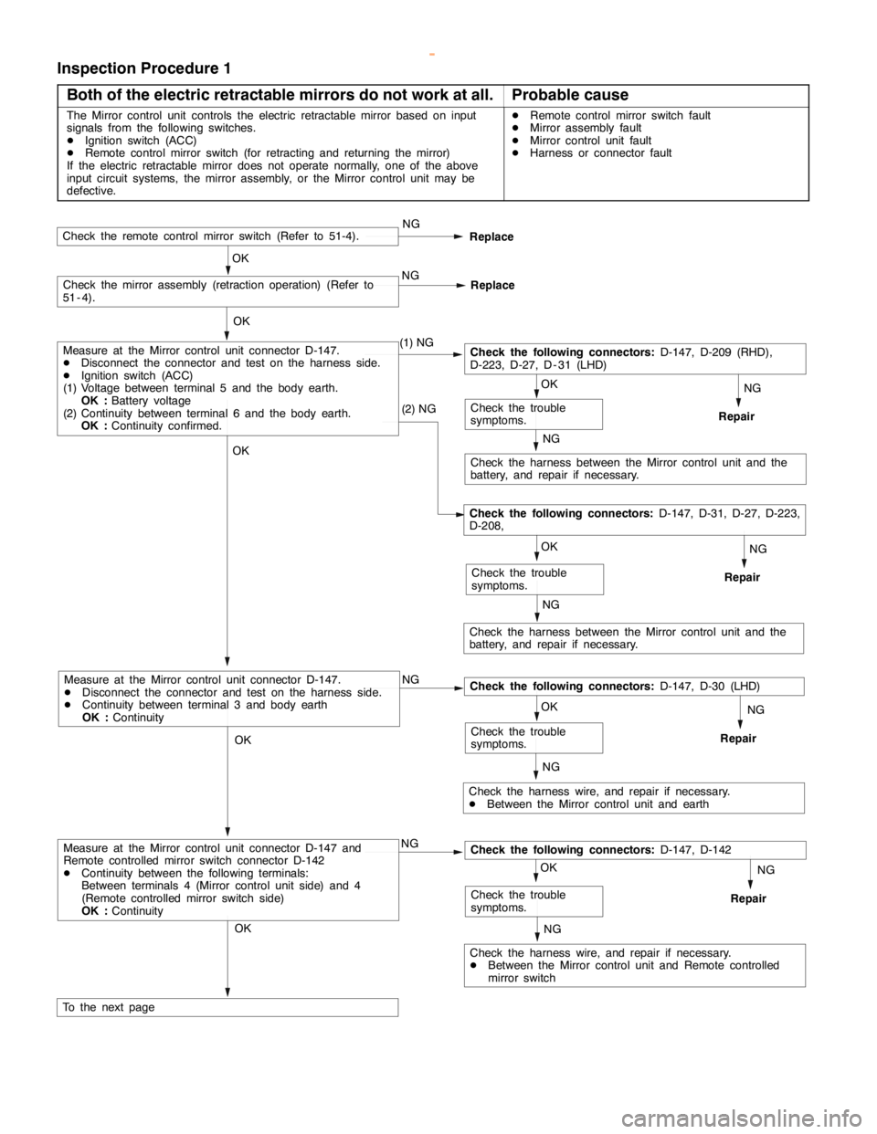
Inspection Procedure 1
Both of the electric retractable mirrors do not work at all.
Probable cause
The Mirror control unit controls the electric retractable mirror based on input
signals from the following switches.
DIgnition switch (ACC)
DRemote control mirror switch (for retracting and returning the mirror)
If the electric retractable mirror does not operate normally, one of the above
input circuit systems, the mirror assembly, or the Mirror control unit may be
defective.DRemote control mirror switch fault
DMirror assembly fault
DMirror control unit fault
DHarness or connector fault
NG
Repair
NG
Check the harness between the Mirror control unit and the
battery, and repair if necessary.
OK
To the next page
OK
Check the trouble
symptoms.
OK
OK
Check the mirror assembly (retraction operation) (Refer to
51 - 4).NG
Replace
Check the remote control mirror switch (Refer to 51-4).NG
Replace
OK
NG
OKNG
Repair
Check the harness wire, and repair if necessary.
DBetween the Mirror control unit and earth
NG
Check the trouble
symptoms.
NG
OK
NG
Check the harness wire, and repair if necessary.
DBetween the Mirror control unit and Remote controlled
mirror switch
NG
Repair OK
Measure at the Mirror control unit connector D-147.
DDisconnect the connector and test on the harness side.
DContinuity between terminal 3 and body earth
OK :Continuity
Check the trouble
symptoms. (1) NG
Measure at the Mirror control unit connector D-147 and
Remote controlled mirror switch connector D-142
DContinuity between the following terminals:
Between terminals 4 (Mirror control unit side) and 4
(Remote controlled mirror switch side)
OK :Continuity
Check the harness between the Mirror control unit and the
battery, and repair if necessary.
Check the trouble
symptoms.
NG
OKNG
Repair
Measure at the Mirror control unit connector D-147.
DDisconnect the connector and test on the harness side.
DIgnition switch (ACC)
(1) Voltage between terminal 5 and the body earth.
OK :Battery voltage
(2) Continuity between terminal 6 and the body earth.
OK :Continuity confirmed.(2) NGCheck the following connectors:D-147, D-209 (RHD),
D-223, D-27, D - 31 (LHD)
Check the following connectors:D-147, D-142
Check the following connectors:D-147, D-30 (LHD)
Check the following connectors:D-147, D-31, D-27, D-223,
D-208,
www.WorkshopManuals.co.uk
Purchased from www.WorkshopManuals.co.uk
Page 1508 of 1839

SRS -Troubleshooting52B-8
Code No.Reference
page Diagnosis item
43*1SRS warning lamp drive circuit systemLamp does not illuminate.52B-14
Lamp does not go out off.52B-14
44*1SRS warning lamp drive circuit system52B-14
45Internal circuit system of non-volatile memory (EEPROM) inside SRS-ECU52B-9
51, 52Driver’s air bag module (squib) system52B-9
54, 55Passenger’s air bag module (squib) system52B-9
71*2,72*2, 75, 76Side air bag module (R.H.) (squib) system52B-15
73, 74Side air bag module (R.H.) (squib) system52B-9
79, 93Side impact sensor (L.H.) communication system52B-16
81*2,82*2, 85, 86Side air bag module (L.H.) (squib) system52B-16
83, 84Side air bag module (L.H.) (squib ignition drive circuit) system52B-9
89, 96Side impact sensor (R.H.) communication system52B-17
91*1Side impact sensor (L.H.) power supply circuit system52B-17
92Analog G-sensor system inside side impact sensor52B-17
94*1Side impact sensor (R.H.) power supply circuit52B-18
95Analog G-sensor system inside side impact sensor (R.H.)52B-17
NOTE
1. *1: If the trouble(s) are extinguished, the SRS warning lamp will go out with diagnosis code history
automatically erased.
2. *2: If the vehicle condition return to normal, the diagnosis code will be automatically erased, and
the SRS warning lamp will return to normal.
3. If the vehicle has a discharged battery, it will store the fault codes 41 or 42. When these diagnosis
codes are displayed, check the battery.
INSPECTION PROCEDURE CLASSIFIED BY DIAGNOSIS CODE
Code No.11, 12 or 13 Front impact sensor systemProbable cause
These diagnosis codes are output if there is abnormal resistance between the
input terminals of the front impact sensors inside the SRS-ECU.
The trouble causes for each diagnosis code No. are as follow.DMalfunction of harness or connector
DMalfunction of front impact sensor
DMalfunction of SRS-ECU
Table 1
Code No.Trouble Symptom
11D
Short circuit in front impact sensor or harness
D
Short circuit in front impact sensor harness leading to the vehicle body ground
D
Short circuit in front impact sensor harness leading to the power supply
12D
Open circuit in either left or right front impact sensor or harness
D
Short circuit in front impact sensor harness leading to the power supply
13D
Open circuit in both left and right front impact sensor or harness
D
Short circuit in front impact sensor harness leading to the power supply
www.WorkshopManuals.co.uk
Purchased from www.WorkshopManuals.co.uk