2000 MITSUBISHI MONTERO battery
[x] Cancel search: batteryPage 1647 of 1839
CHASSIS ELECTRICAL -Radio/Tape Player54A-77
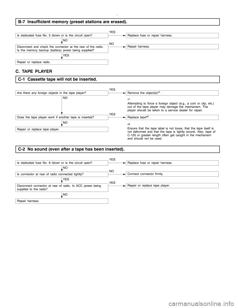
B-7 Insufficient memory (preset stations are erased).
Is dedicated fuse No. 5 blown or is the circuitopen?YESReplace fuse or repair harness.
NO
Disconnect and check the connector at the rear of the radio.
Is the memory backup (battery) powerbeing supplied?NORepair harness.
YES
Repair or replace radio.
C. TAPE PLAYER
C-1 Cassette tape will not be inserted.
Are there any foreign objects in the tape player?YESRemove the object(s)*1.
NO*1
Attempting to force a foreign object (e.g., a coin or clip, etc.)
out of the tape player maydamage the mechanism. The
player should be taken to a service dealer for repair.
Does the tape player work if another tape is inserted?YESReplace tape*2.
NO
Repair or replace tape player.
*2
Ensure that the tape label is not loose, that the tape itself is
not deformed and that the tape is tightly wound. Also, tape of
C-120 or greater length often get caught in the mechanism
and should not be used.
C-2 No sound (even after a tape has been inserted).
Is dedicated fuse No. 6 blown or is the circuitopen?YESReplace fuse or repair harness.
NO
Is connector at rear of radio connected tightly?NOConnect connector firmly.
YES
Disconnect connector at rear of radio. Is ACC powerbeing
supplied to the radio?YESRepair or replace tape player.
NO
Repair harness.
www.WorkshopManuals.co.uk
Purchased from www.WorkshopManuals.co.uk
Page 1679 of 1839
CHASSIS ELECTRICAL -RV MeterCHASSIS ELECTRICAL -RV MeterCHASSIS ELECTRICAL -RV Meter54A-18
Termi-Input/out-
t
Signal sym-
bl
Terminal
lt
Harness problemTrouble symptoms when there is a
hblnal No.
p
put
gy
bolvoltage
(V)Open
circuitshort-cir-
cuit
yp
harness problem
29 - 30––––––
31–EARTH
(TEMP)––––
32–ILL - (illumi-
nation lamp
adjustment
signal)–ExistsExistsUnable to adjust illumination lamp
33InputFUEL
GAUGE0-3ExistsExists–
34 - 36––––––
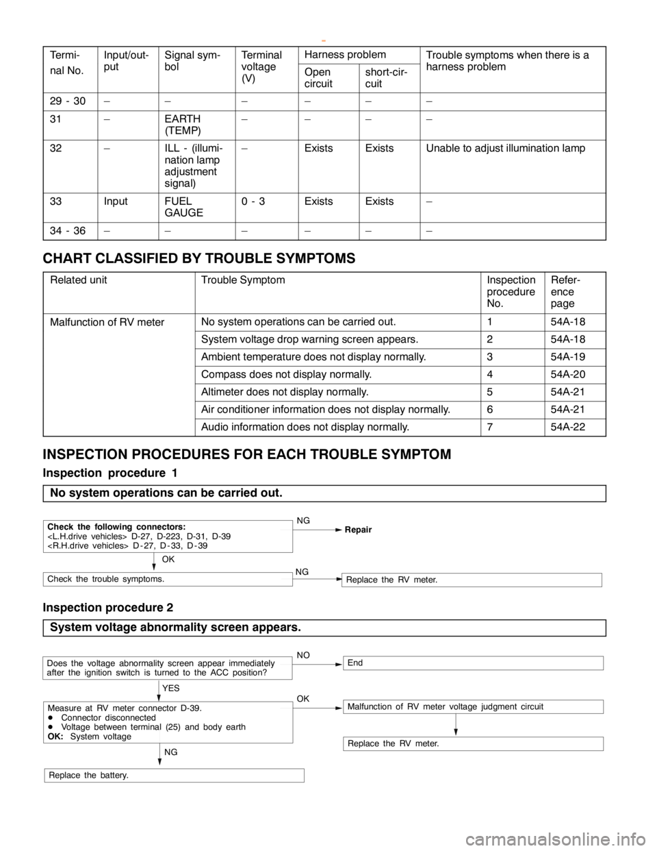
CHART CLASSIFIED BY TROUBLE SYMPTOMS
Related unitTrouble SymptomInspection
procedure
No.Refer-
ence
page
Malfunction of RV meterNo system operations can be carried out.154A-18
System voltage drop warning screen appears.254A-18
Ambient temperature does not display normally.354A-19
Compass does not display normally.454A-20
Altimeter does not display normally.554A-21
Air conditioner information does not display normally.654A-21
Audio information does not display normally.754A-22
INSPECTION PROCEDURES FOR EACH TROUBLE SYMPTOM
Inspection procedure 1
No system operations can be carried out.
NG
OK
Check the following connectors:
Check the trouble symptoms.NGReplace the RV meter.
Inspection procedure 2
System voltage abnormality screen appears.
NOEnd
OK YES
Replace the battery.
Replace the RV meter.
NG
Does the voltage abnormality screen appear immediately
after the ignition switch is turned to the ACC position?
Malfunction of RV meter voltage judgment circuitMeasure at RV meter connector D-39.
DConnector disconnected
DVoltage between terminal (25) and body earth
OK:System voltage
www.WorkshopManuals.co.uk
Purchased from www.WorkshopManuals.co.uk
Page 1691 of 1839

SWS -General InformationSWS -General Information54B-5
HEADLAMP WASHER
If the headlamp washer switch at the steering
column is placed in the ON position when the ignition
switch is in the ACC or ON position and theheadlamp switch is in the ON position, the headlamp
washer drive signal is turned ON for 0.5 second.
IGNITION KEY HOLE ILLUMINATION LAMP
When the ignition switch is turned to LOCK (OFF) or
ACC position with the driver’s door opened, the
ignition key hole illumination lamp is illuminated.
If the door is closed in that state, the lamp goes out
after 30 seconds. Vehicles with keyless entrysystem, it illuminates for 30 seconds after the
ignition key is removed. In either case the lamp goes
out when the ignition switch is turned to ON position.
HEADLAMP
Headlamp Automatic Shutdown Function
If the ignition switch is turned to LOCK (OFF) or
ACC position, when the headlamps are on, the
headlamps will be switched off in three minutes.
If the driver’s door is opened within that three-minute
period, the headlamps will be switched off
automatically. This prevents the battery from
discharged.
In addition, if the headlamps are turned on when
the ignition switch is at LOCK (OFF) or ACC position,
the headlamps will not be switched off.Headlamp Dimmer Switch Automatic Reset
Function
This function allows the dimmer switch to be reset
to the low-beam position whenever the headlamp
switch is turned ON.
Daytime Running Lamp (DRL) Function
If the ignition switch is turned to ON when the
headlamps and tail lamps are off, the headlamps
(low-beam) and tail lamps turn on.
FLASHER TIMER
Turn-signal Lamp
When the ignition switch is turned to ON position
and turn-signal lamp switch is placed in the ON
position for right or left turn signaling, the system
generates turn-signal lamp drive signals (flashing
signals).
The system also notifies of a blown turn-signal lamp
bulb by shortening the flashing intervals of the
corresponding indicator lamp.Hazard Warning Lamp
The system detects a change from ON to OFF
of the hazard lamp input signal and activates the
hazard lamps if they are not in operation or
deactivates the lamps if they are operating (reversal
of state between activation and deactivation).
FRONT FOG LAMP
If the front fog lamp switch is turned ON at the
condition that the headlamp or the tail lamp is turned
ON (including the illumination by the automatic
lighting function), the front fog lamp is turned ON.Whenever the tail lamps are turned on at the next
time, the front fog lamps will always be off regardless
of the switch positions. In addition, if the tail lamp
is switched off by the automatic lighting system,
the front fog lamp will also be switched off. However,
the front fog lamp will be illuminated when the tail
lamp is switched on.
www.WorkshopManuals.co.uk
Purchased from www.WorkshopManuals.co.uk
Page 1703 of 1839
SWS -TroubleshootingSWS -Troubleshooting54B-17
INSPECTION PROCEDURE FOR TROUBLE SYMPTOMS
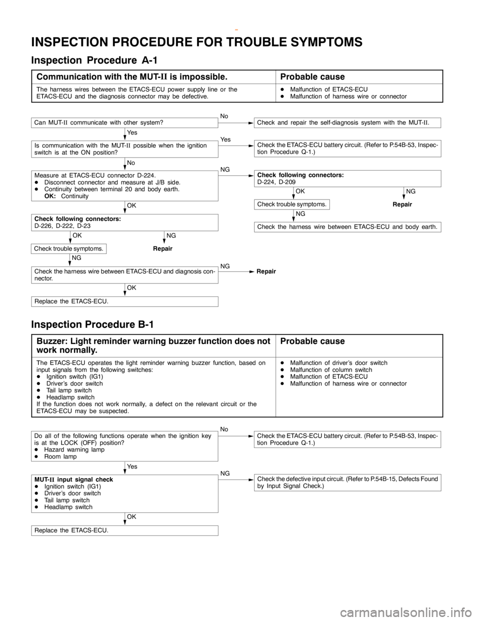
Inspection Procedure A-1
Communication with the MUT-II
is impossible.Probable cause
The harness wires between the ETACS-ECU power supply line or the
ETACS-ECU and the diagnosis connector may be defective.DMalfunction of ETACS-ECU
DMalfunction of harness wire or connector
Ye s
Ye s
Check the ETACS-ECU battery circuit. (Refer to P.54B-53, Inspec-
tion Procedure Q-1.)
No
NG
NG
Repair
NG
Check the harness wire between ETACS-ECU and body earth.
OK
OK
Replace the ETACS-ECU.
NG
Repair
NG
Check the harness wire between ETACS-ECU and diagnosis con-
nector.NG
Repair
OK
Check trouble symptoms.
Check following connectors:
D-226, D-222, D-23
OK
Check trouble symptoms.
Check following connectors:
D-224, D-209Measure at ETACS-ECU connector D-224.
DDisconnect connector and measure at J/B side.
DContinuity between terminal 20 and body earth.
OK:Continuity
Is communication with the MUT-
IIpossible when the ignition
switch is at the ON position?
Can MUT-
IIcommunicate with other system?NoCheck and repair the self-diagnosis system with the MUT-
II.
Inspection Procedure B-1
Buzzer: Light reminder warning buzzer function does not
work normally.Probable cause
The ETACS-ECU operates the light reminder warning buzzer function, based on
input signals from the following switches:
DIgnition switch (IG1)
DDriver’s door switch
DTail lampswitch
DHeadlamp switch
If the function does not work normally, a defect on the relevant circuit or the
ETACS-ECU may be suspected.DMalfunction of driver’s door switch
DMalfunction of column switch
DMalfunction of ETACS-ECU
DMalfunction of harness wire or connector
NoCheck the ETACS-ECU battery circuit. (Refer to P.54B-53, Inspec-
tion Procedure Q-1.)
Ye s
NG
Check the defective input circuit. (Refer to P.54B-15, Defects Found
by Input Signal Check.)
OK
Replace the ETACS-ECU.
Do all of the following functions operate when the ignition key
is at the LOCK (OFF) position?
DHazard warninglamp
DRoom lamp
MUT-
IIinput signal check
DIgnition switch (IG1)
DDriver’s door switch
DTail lampswitch
DHeadlamp switch
www.WorkshopManuals.co.uk
Purchased from www.WorkshopManuals.co.uk
Page 1710 of 1839
SWS -TroubleshootingSWS -Troubleshooting54B-24
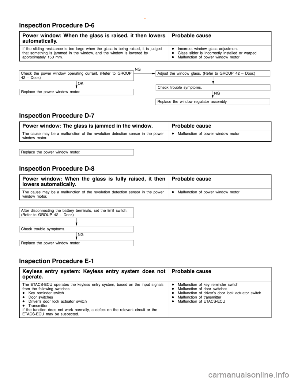
Inspection Procedure D-6
Power window: When the glass is raised, it then lowers
automatically.Probable cause
If the sliding resistance is too large when the glass isbeing raised, it is judged
that something is jammed in the window, and the window is lowered by
approximately 150 mm.DIncorrect window glass adjustment
DGlass slider is incorrectly installed or warped
DMalfunction of power window motor
OK
Replace the power window motor.NG
Replace the window regulator assembly.
Check trouble symptoms.
Check the power window operating currant. (Refer to GROUP
42 – Door.)NGAdjust the window glass. (Refer to GROUP 42 – Door.)
Inspection Procedure D-7
Power window: The glass is jammed in the window.Probable cause
The cause may be a malfunction of the revolution detection sensor in the power
window motor.DMalfunction of power window motor
Replace the power window motor.
Inspection Procedure D-8
Power window: When the glass is fully raised, it then
lowers automatically.Probable cause
The cause may be a malfunction of the revolution detection sensor in the power
window motor.DMalfunction of power window motor
NG
Replace the power window motor.
Check trouble symptoms.
After disconnecting the battery terminals, set the limit switch.
(Refer to GROUP 42 - Door.)
Inspection Procedure E-1
Keyless entry system: Keyless entry system does not
operate.Probable cause
The ETACS-ECU operates the keyless entry system, based on the input signals
from the following switches:
DKey reminder switch
DDoor switches
DDriver’s door lock actuator switch
DTransmitter
If the function does not work normally, a defect on the relevant circuit or the
ETACS-ECU may be suspected.DMalfunction of key reminder switch
DMalfunction of door switches
DMalfunction of driver’s door lock actuator switch
DMalfunction of transmitter
DMalfunction of ETACS-ECU
www.WorkshopManuals.co.uk
Purchased from www.WorkshopManuals.co.uk
Page 1711 of 1839
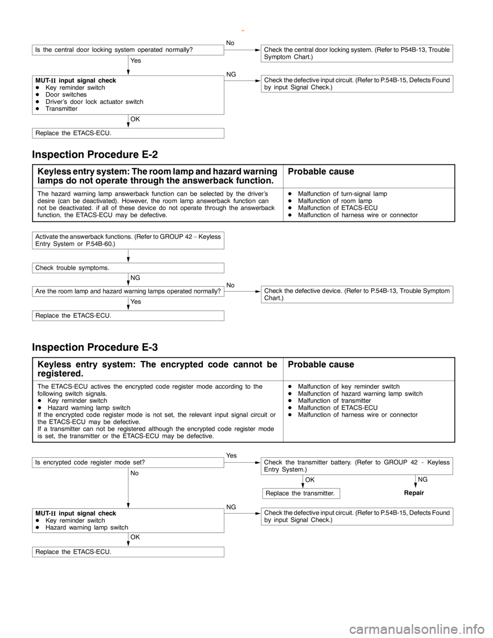
SWS -Troubleshooting54B-25
OK
Replace the ETACS-ECU.
NoCheck the central door locking system. (Refer to P54B-13, Trouble
Symptom Chart.)
Ye s
MUT-
IIinput signal check
DKey reminder switch
DDoor switches
DDriver’s door lock actuator switch
DTransmitterNGCheck the defective input circuit. (Refer to P.54B-15, Defects Found
by input Signal Check.)
Is the central door locking system operated normally?
Inspection Procedure E-2
Keyless entry system: The room lamp and hazard warning
lamps do not operate through the answerback function.Probable cause
The hazard warninglampanswerback function can be selected by the driver’s
desire (can be deactivated). However, the roomlampanswerback function can
not be deactivated. if all of these device do not operate through the answerback
function, the ETACS-ECU may be defective.DMalfunction of turn-signal lamp
DMalfunction of room lamp
DMalfunction of ETACS-ECU
DMalfunction of harness wire or connector
Ye s
Replace the ETACS-ECU.
NG
Are the room lamp andhazard warning lamps operated normally?NoCheck the defective device. (Refer to P.54B-13, Trouble Symptom
Chart.)
Check trouble symptoms.
Activate the answerback functions. (Refer to GROUP 42 – Keyless
Entry System or P.54B-60.)
Inspection Procedure E-3
Keyless entry system: The encrypted code cannot be
registered.Probable cause
The ETACS-ECU actives the encrypted code registermode according to the
following switch signals.
DKey reminder switch
DHazard warninglampswitch
If the encrypted code registermode is notset, the relevant input signal circuit or
the ETACS-ECU may be defective.
If a transmitter can not be registered although the encrypted code registermode
is set, the transmitter or the ETACS-ECU may be defective.DMalfunction of key reminder switch
DMalfunction of hazard warninglampswitch
DMalfunction of transmitter
DMalfunction of ETACS-ECU
DMalfunction of harness wire or connector
OK
Replace the ETACS-ECU.
Ye s
No
NG
Check the defective input circuit. (Refer to P.54B-15, Defects Found
by input Signal Check.)NG
Repair OKReplace the transmitter.
MUT-
IIinput signal check
DKey reminder switch
DHazard warninglampswitch
Is encrypted code registermodeset?Check the transmitter battery. (Refer to GROUP 42 - Keyless
Entry System.)
www.WorkshopManuals.co.uk
Purchased from www.WorkshopManuals.co.uk
Page 1720 of 1839
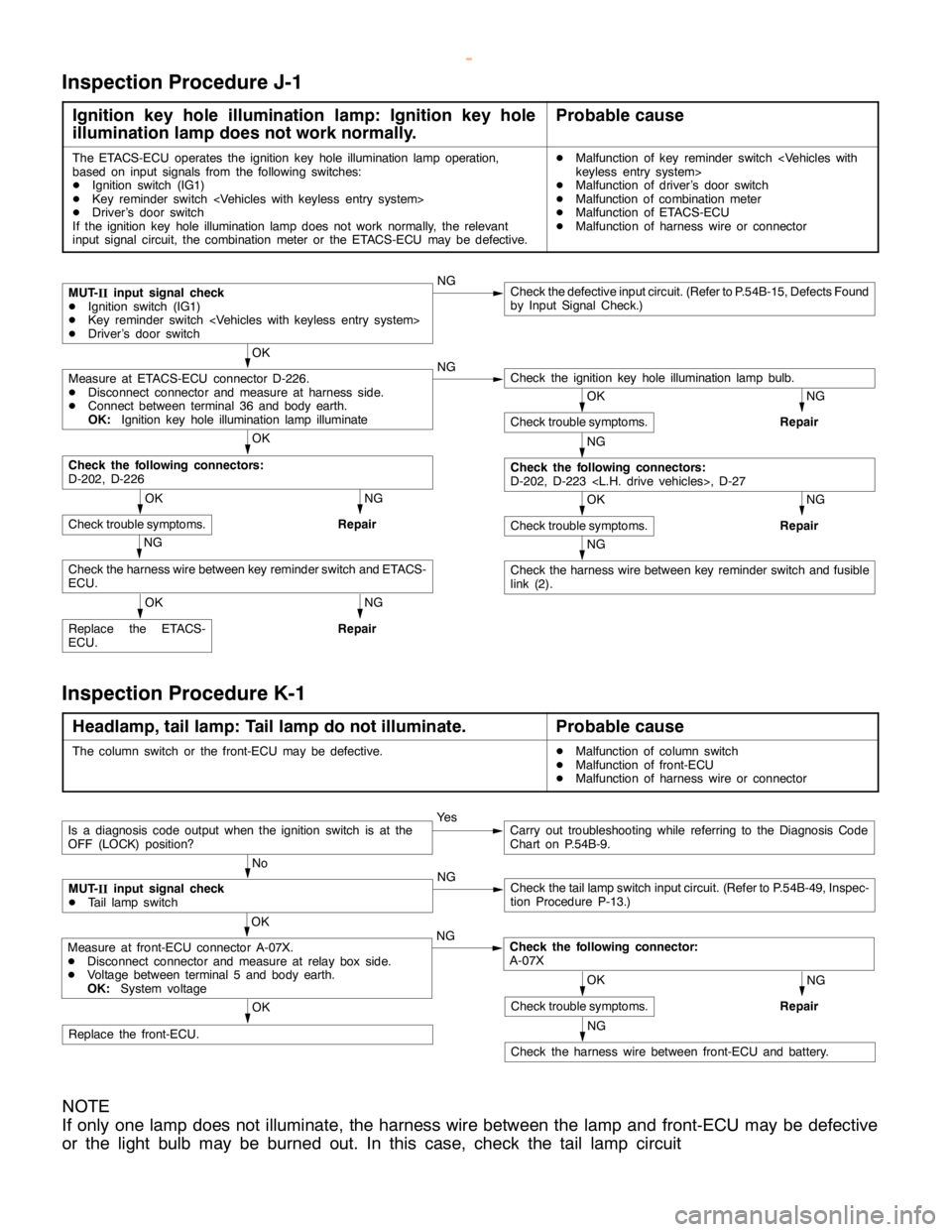
SWS -TroubleshootingSWS -Troubleshooting54B-34
Inspection Procedure J-1
Ignition key hole illumination lamp: Ignition key hole
illumination lamp does not work normally.Probable cause
The ETACS-ECU operates the ignition keyhole illumination lamp operation,
based on input signals from the following switches:
DIgnition switch (IG1)
DKey reminder switch
DDriver’s door switch
If the ignition key hole illumination lampdoes not work normally, the relevant
input signal circuit, the combination meter or the ETACS-ECU may be defective.DMalfunction of key reminder switch
DMalfunction of driver’s door switch
DMalfunction of combination meter
DMalfunction of ETACS-ECU
DMalfunction of harness wire or connector
NGCheck the defective input circuit. (Refer to P.54B-15, Defects Found
by Input Signal Check.)
OK
NG
NG
Repair
OK
NG
Repair
NG
NG
Repair
OK
Replace the ETACS-
ECU.
NG
Repair
NG
Check the harness wire between key reminder switch and fusible
link (2).
OK
Check trouble symptoms.
NG
Check the following connectors:
D-202, D-223
OK
Check trouble symptoms.
Check the harness wire between key reminder switch and ETACS-
ECU.
OK
Check trouble symptoms.
Check the following connectors:
D-202, D-226
Check the ignition keyhole illumination lamp bulb.Measure at ETACS-ECU connector D-226.
DDisconnect connector and measure at harness side.
DConnect between terminal 36 and body earth.
OK:Ignition key hole illumination lamp illuminate
MUT-
IIinput signal check
DIgnition switch (IG1)
DKey reminder switch
DDriver’s door switch
Inspection Procedure K-1
Headlamp, tail lamp: Tail lamp do not illuminate.Probable cause
The column switch or the front-ECU may be defective.DMalfunction of column switch
DMalfunction of front-ECU
DMalfunction of harness wire or connector
OK
Replace the front-ECU.
Ye sCarry out troubleshooting while referring to the Diagnosis Code
Chart on P.54B-9.
No
NG
Check the taillampswitch input circuit. (Refer to P.54B-49, Inspec-
tion Procedure P-13.)
NG
Repair
NG
Check the harness wire between front-ECU and battery.
OK
Check trouble symptoms.
OK
NG
Check the following connector:
A-07XMeasure at front-ECU connector A-07X.
DDisconnect connector and measure at relay box side.
DVoltage between terminal 5 and body earth.
OK:System voltage
MUT-
IIinput signal check
DTail lampswitch
Is a diagnosis code output when the ignition switch is at the
OFF (LOCK) position?
NOTE
If only one lamp does not illuminate, the harness wire between the lamp and front-ECU may be defective
or the light bulb may be burned out. In this case, check the tail lamp circuit
www.WorkshopManuals.co.uk
Purchased from www.WorkshopManuals.co.uk
Page 1721 of 1839
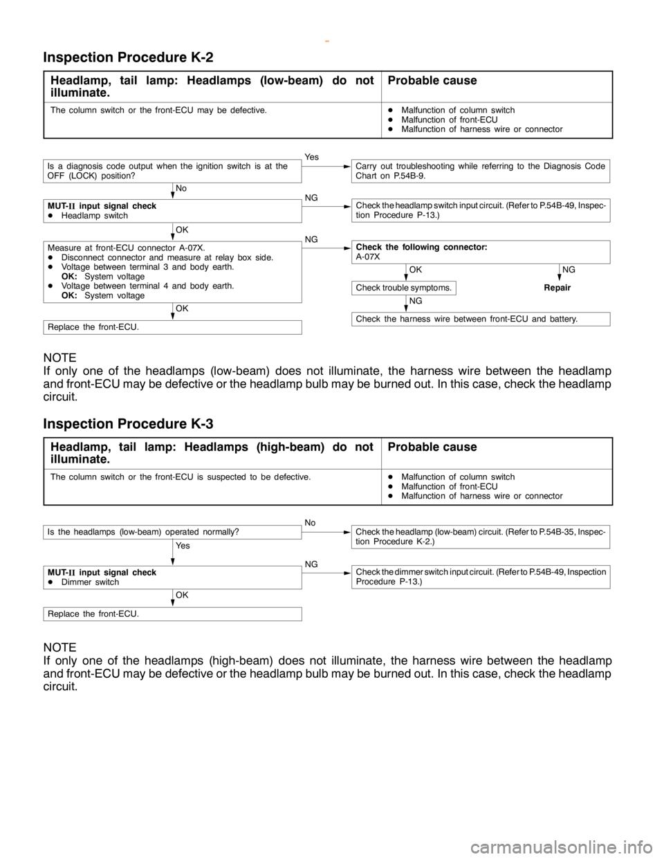
SWS -Troubleshooting54B-35
Inspection Procedure K-2
Headlamp, tail lamp: Headlamps (low-beam) do not
illuminate.Probable cause
The column switch or the front-ECU may be defective.DMalfunction of column switch
DMalfunction of front-ECU
DMalfunction of harness wire or connector
OK
Replace the front-ECU.
No
NG
Check theheadlampswitch input circuit. (Refer to P.54B-49, Inspec-
tion Procedure P-13.)
Ye sCarry out troubleshooting while referring to the Diagnosis Code
Chart on P.54B-9.
NG
Repair
NG
Check the harness wire between front-ECU and battery.
OK
Check trouble symptoms.
OK
NG
Check the following connector:
A-07XMeasure at front-ECU connector A-07X.
DDisconnect connector and measure at relay box side.
DVoltage between terminal 3 and body earth.
OK:System voltage
DVoltage between terminal 4 and body earth.
OK:System voltage
MUT-
IIinput signal check
DHeadlamp switch
Is a diagnosis code output when the ignition switch is at the
OFF (LOCK) position?
NOTE
If only one of the headlamps (low-beam) does not illuminate, the harness wire between the headlamp
and front-ECU may be defective or the headlamp bulb may be burned out. In this case, check the headlamp
circuit.
Inspection Procedure K-3
Headlamp, tail lamp: Headlamps (high-beam) do not
illuminate.Probable cause
The column switch or the front-ECU is suspected to be defective.DMalfunction of column switch
DMalfunction of front-ECU
DMalfunction of harness wire or connector
OK
Replace the front-ECU.
Is the headlamps (low-beam) operated normally?NoCheck theheadlamp (low-beam)circuit. (Refer to P.54B-35, Inspec-
tion Procedure K-2.)
Ye s
MUT-
IIinput signal check
DDimmer switchNGCheck the dimmer switch input circuit. (Refer to P.54B-49, Inspection
Procedure P-13.)
NOTE
If only one of the headlamps (high-beam) does not illuminate, the harness wire between the headlamp
and front-ECU may be defective or the headlamp bulb may be burned out. In this case, check the headlamp
circuit.
www.WorkshopManuals.co.uk
Purchased from www.WorkshopManuals.co.uk