2000 MITSUBISHI MONTERO battery
[x] Cancel search: batteryPage 1568 of 1839

SRS -Seat Belt Pre-tensioner Disposal ProceduresSRS -Seat Belt Pre-tensioner Disposal Procedures52B-16
Caution
1) Before operating the pre-tensioner, see that
no one is in and near the vehicle.
2) The operation of the pre-tensioner makes the
inflator very hot. Before handling the inflator,
wait more than 30 minutes for cooling.
3) If the pre-tensioner fails to operate when the
procedures above are followed, do not go near
the pre-tensioner. Contact your local
distributor.
(7) After operation of the pre-tensioner, discard as
specified in the procedure. (Refer to P.52B-18.)
DEPLOYMENT OUTSIDE THE VEHICLE
Caution
1) This should be carried out in a wide, flat area at least
6 m away from obstacles and other people.
2) Do not operate outside if wind is high. Even in a soft
wind, ignite to windward of the pre-tensioner.
1. Disconnect the negative ( - ) and positive (+) battery cables
from the battery terminals, and then remove the battery
from the vehicle.
Caution
Wait at least 60 seconds after disconnecting the
battery cables before doing any further work. (Refer
to P.52B-4.)
2. Operate pre-tensioner as specified in the service
procedures that follows.
(1) Remove the seat belt pre-tensioner from the vehicle.
(Refer to P.52B-12.)
Caution
The pre-tensioner should be stored on a flat
surface and placed so that the pre-tensioner
operation surfaces are facing upward. Do not
place anything on top of them.
www.WorkshopManuals.co.uk
Purchased from www.WorkshopManuals.co.uk
Page 1572 of 1839

54A-2
CHASSIS
ELECTRICAL
CONTENTS
BATTERY 4
..............................
SERVICE SPECIFICATIONS 4..................
ON-VEHICLE SERVICE 4......................
Electrolyte Level and Specific Gravity Check 4..
Charging 5.................................
Battery Test 5...............................
IGNITION SWITCH AND IMMOBILIZER
SPECIAL TOOLS 6............................
TROUBLESHOOTING 6........................
IGNITION SWITCH AND
IMMOBILIZER-ECU 11.........................
IGNITION SWITCH AND IMMOBILIZER
<4D56> 14...............................
SPECIAL TOOLS 14...........................
TROUBLESHOOTING 14.......................
IGNITION SWITCH AND IMMOBILIZER-ECU
19 ............................................
COMBINATION METER 23................
SERVICE SPECIFICATIONS 23.................
SEALANTS 24................................
SPECIAL TOOLS 24...........................
TROUBLESHOOTING 24.......................
ON-VEHICLE SERVICE 30.....................
Speedometer Check 30......................
Tachometer Check 30........................
Fuel Gauge Unit Check 31....................Engine Coolant Temperature Gauge Unit Check
32 .........................................
COMBINATION METER 33.....................
HEADLAMP ASSEMBLY 36...............
SERVICE SPECIFICATIONS 36.................
SPECIAL TOOLS 36...........................
TROUBLESHOOTING 36.......................
ON-VEHICLE SERVICE 36.....................
Headlamp Aiming Adjustment 36..............
Luminance Measurement 38..................
Headlamp Bulb Replacement 39...............
HEADLAMP ASSEMBLY 40....................
FOG LAMPS 41..........................
SERVICE SPECIFICATIONS 41.................
SPECIAL TOOLS 41...........................
TROUBLESHOOTING 41.......................
ON-VEHICLE SERVICE 41.....................
Fog Lamp Aiming Check 41...................
FOG LAMPS 44...............................
SIDE TURN-SIGNAL LAMPS 45...........
SPECIAL TOOLS 45...........................
SIDE TURN-SIGNAL LAMPS 46................
ROOM LAMP 46.........................
TROUBLESHOOTING 46.......................
CONTINUED ON NEXT PAGE
www.WorkshopManuals.co.uk
Purchased from www.WorkshopManuals.co.uk
Page 1575 of 1839

CHASSIS ELECTRICAL-Battery54A-5
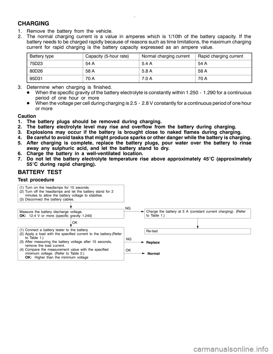
CHARGING
1. Remove the battery from the vehicle.
2. The normal charging current is a value in amperes which is 1/10th of the battery capacity. If the
battery needs to be charged rapidly because of reasons such as time limitations, the maximum charging
current for rapid charging is the battery capacity expressed as an ampere value.
Battery typeCapacity (5-hour rate)Normal charging currentRapid charging current
75D2354 A5.4 A54 A
80D2658 A5.8 A58 A
95D3170 A7.0 A70 A
3. Determine when charging is finished.
DWhen the specific gravity of the battery electrolyte is constantly within 1.250 - 1.290 for a continuous
period of one hour or more
DWhen the voltage per cell during charging is 2.5 - 2.8 V constantly for a continuous period of one hour
or more
Caution
1. The battery plugs should be removed during charging.
2. The battery electrolyte level may rise and overflow from the battery during charging.
3. Explosions may occur if the battery is brought close to naked flames during charging.
4. Be careful to avoid tasks that might produce sparks or other danger while the battery is charging.
5. After charging is complete, replace the battery plugs, pour water over the battery to rinse
away any sulphuric acid, and let the battery stand to dry.
6. Charge the battery in a well-ventilated location.
7. Do not let the battery electrolyte temperature rise above approximately 45
°C (approximately
55
°C during rapid charging).
BATTERY TEST
Test procedure
OK
NG
Replace
Re-test
OK
Normal
(1) Connect a battery tester to the battery.
(2) Apply aloadwith the specified current to the battery.(Refer
to Table 1.)
(3) After measuring the battery voltage after 15 seconds,
remove the loadcurrent.
(4) Compare the measurement value with the specified
minimum voltage.(Refer to Table 2.)
OK:Higher than the minimum voltage
Measure the battery discharge voltage.
OK:12.4 V or more (specific gravity 1.240)NGCharge the battery at 5 A (constant current charging). (Refer
to Table 1.)
(1) Turn on the headlamps for 15 seconds.
(2) Turn off the headlamps and let the battery stand for 2
minutes to allow the battery voltage to stabilise.
(3) Disconnect the battery cables.
www.WorkshopManuals.co.uk
Purchased from www.WorkshopManuals.co.uk
Page 1579 of 1839

CHASSIS ELECTRICAL-Ignition Switch and Immobilizer
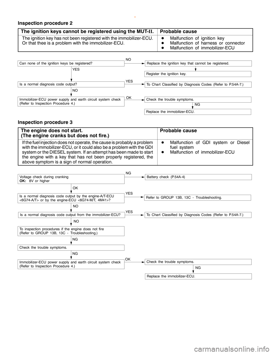
Inspection procedure 2
The ignition keys cannot be registered using the MUT-II.
Probable cause
The ignition key has not been registered with the immobilizer-ECU.
Or that thee is a problem with the immobilizer-ECU.D
Malfunction of ignition key
D
Malfunction of harness or connector
D
Malfunction of immobilizer-ECU
Register the ignition key.
YES
NO YESIs a normal diagnosis code output?
NOCan none of the ignitionkeys beregistered?Replace the ignition key that cannot be registered.
To Chart Classified by Diagnosis Codes (Refer to P.54A-7.)
OKImmobilizer-ECU power supply and earth circuit system check
(Refer to Inspection Procedure 4.)
NG
Replace the immobilizer-ECU.
Check the trouble symptoms.
Inspection procedure 3
The engine does not start.
(The engine cranks but does not fire.)
Probable cause
If the fuel injection does not operate, the cause is probably a problem
with the immobilizer-ECU, or it could also be a problem with the GDI
system or the DIESEL system. If an attempt has been made to start
the engine with a key that has not been properly registered, the
above symptom is a sign of normal operation.D
Malfunction of GDI system or Diesel
fuel system
D
Malfunction of immobilizer-ECU
NGBattery check (P.54A-4)
YES
NO
Refer to GROUP 13B, 13C - Troubleshooting.YES
NO
To Chart Classified by Diagnosis Codes (Refer to P.54A-7.)Is a normal diagnosis code output from the immobilizer-ECU?
OK
Voltage check during cranking
OK:8V or higher
NG
OKImmobilizer-ECU power supply and earth circuit system check
(Refer to Inspection Procedure 4.)
NG
Replace the immobilizer-ECU.
Check the trouble symptoms.
Check the trouble symptoms.
NG
To inspection procedures if the enginedoes not fire
(Refer to GROUP 13B, 13C - Troubleshooting.)
Is a normal diagnosis code output by the engine-A/T-ECU
<6G74-A/T> or by the engine-ECU <6G74-M/T, 4M41>?
www.WorkshopManuals.co.uk
Purchased from www.WorkshopManuals.co.uk
Page 1587 of 1839

CHASSIS ELECTRICAL-Ignition Switch and Immobilizer <4D56>54A-17
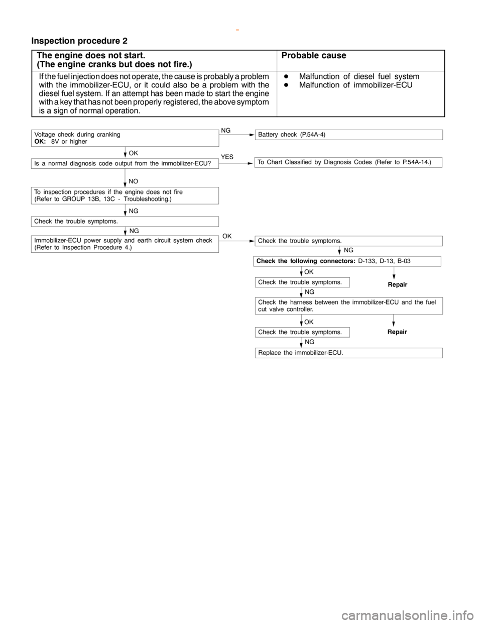
Inspection procedure 2
The engine does not start.
(The engine cranks but does not fire.)
Probable cause
If the fuel injection does not operate, the cause is probably a problem
with the immobilizer-ECU, or it could also be a problem with the
diesel fuel system. If an attempt has been made to start the engine
with a key that has not been properly registered, the above symptom
is a sign of normal operation.D
Malfunction of diesel fuel system
D
Malfunction of immobilizer-ECU
NGBattery check (P.54A-4)
YES
NOTo Chart Classified by Diagnosis Codes (Refer to P.54A-14.)Is a normal diagnosis code output from the immobilizer-ECU?
OK
Voltage check during cranking
OK:8V or higher
NG
Immobilizer-ECU power supply and earth circuit system check
(Refer to Inspection Procedure 4.)
Check the trouble symptoms.
NG
To inspection procedures if the enginedoes not fire
(Refer to GROUP 13B, 13C - Troubleshooting.)
OK
Check the trouble symptoms.
NG
OK
NG
Replace the immobilizer-ECU.
Check the trouble symptoms.
OK
Check the trouble symptoms.
NG
Repair
Check the harness between the immobilizer-ECU and the fuel
cut valve controller.
Repair
Check the following connectors:D-133, D-13, B-03
www.WorkshopManuals.co.uk
Purchased from www.WorkshopManuals.co.uk
Page 1593 of 1839

CHASSIS ELECTRICAL-Combination Meter54A-23
COMBINATION METER
SERVICE SPECIFICATIONS
ItemStandard valueLimit
Speedometer indication rangeAt 20 km/h18 - 23–
km/hAt 40 km/h37 - 45–
At 80 km/h75 - 88–
At 120 km/h113 - 132–
At 160 km/h150 - 176–
Speedometer needle swing km/h (when driving at 35 km/h or higher)–±3
Tachometer indication errorWhen engine speed is 700 r/min±120–
r/minWhen engine speed is 2,000 r/minPetrol- 175+225–
Diesel±175–
When engine speed is 3,000 r/minPetrol- 175+300–
Diesel±225–
When engine speed is 4,000 r/minPetrol- 225+375–
Diesel±300–
When engine speed is 4,750 r/min
When engine speed is 5,000 r/min
When engine speed is 6,000 r/min
Fuel gauge unit standardF position3–
resistance valueWE position11 0–
Fuel gauge unit float heightF position11.9–
mmE position195.2–
Engine coolant temperature gauge unit standard resistance valueW104±13.5–
Combination meter internal62 - 11 (IG power supply - earth)1MWor more–
resistance valueW62 - 25 (IG power supply - earth)1MWor more–(Measured at connector D-38
and connector D-40)
62 - 63 (IG power supply - fuel gauge)1MWor more–
62 - 64 (IG power supply - engine coolant
temperature gauge)1MWor more–
63 - 11 (fuel gauge - earth)180–
63 - 25 (fuel gauge - earth)180–
64 - 11 (engine coolant temperature gauge - earth)210–
64 - 25 (engine coolant temperature gauge - earth)210–
67 - 11 (battery power supply - earth)1MWor more–
67 - 25 (battery power supply - earth)1MWor more–
67 - 63 (battery power supply - fuel gauge)1MWor more–
67 - 64 (battery power supply - engine coolant
temperature gauge)1MWor more–
www.WorkshopManuals.co.uk
Purchased from www.WorkshopManuals.co.uk
Page 1624 of 1839

CHASSIS ELECTRICAL -Clock or Center Display54A-54
BEFORE REMOVING THE BATTERY
The Center display has a large amount of data unique to the vehicle in its memory. When the battery
cable is disconnected, that memory is affected as shown in the table below. Accordingly, it is necessary
to make sure that you take notes of important information before disconnecting the battery cable.
FunctionInput function/memoryWhen battery cable is disconnected
Clock set on displayCurrent timeRetains data for approx. 1 hour
Vehicle model setShort (3-door models)/long (5-door
models)Retains data for approx. 1 hour
Brightness set for displayPosition set on displayRetains data for approx. 1 hour
Unit set for trip computerkm or mile, L/100km or mpg or km/L
Average vehicle speed after resetRetains data for approx. 1 hour
Average vehicle speed on displayAverage vehicle speed after resetRetains data for approx. 1 hour
Average fuel consumption on displayAverage fuel consumption after resetRetains data for approx. 1 hour
Cruising range on displayCruising range, fuel economyRetains data for approx. 1 hour
Outside temperature on displayOutside temperature after the ignition
switch is turned to the OFF(LOCK)
position.Retains data for approx. 1 hour
* The outside temperature sensor
is located near the engine.
Therefore, incorrectly high
temperature may be displayed
when the battery cable is
reconnected within one hour.
DIAGNOSIS FUNCTION FOR CENTER DISPLAY
Center display has the following diagnosis function:
FunctionContents
Service functionThere are the following 4 diagnosis modes available
1. Check of vehicle informationThe vehicle, short (3-door models)/long (5-door models) set
2. Check of LCD segmentsThe LCD segments for display available to light on or not
3. Check of sensorsOutside temperature, voltage of fuel gauge unit, system voltage, fuel amount
remains, fuel economy calculated after supply of fuel
4. Check of units connected into
the center displayThe units connected on display
Voltage (%) on terminal for MUT-II
Vehicle speed signal sent by engine-ECU
Oscillating signal
www.WorkshopManuals.co.uk
Purchased from www.WorkshopManuals.co.uk
Page 1632 of 1839

CHASSIS ELECTRICAL -Clock or Center Display54A-62
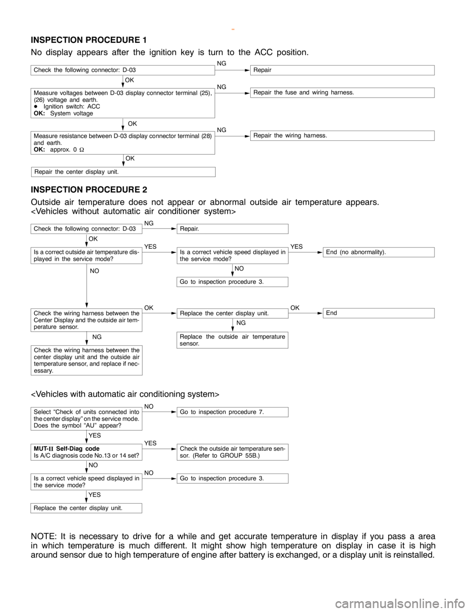
INSPECTION PROCEDURE 1
No display appears after the ignition key is turn to the ACC position.
OK
Measure voltages between D-03 display connector terminal (25),
(26) voltage and earth.
DIgnition switch: ACC
OK:System voltageNGRepair the fuse and wiring harness.
OK
Measure resistance between D-03 display connector terminal (28)
and earth.
OK:approx. 0
WNGRepair the wiring harness.
OK
Repair the center display unit.
Check the following connector: D-03NGRepair
INSPECTION PROCEDURE 2
Outside air temperature does not appear or abnormal outside air temperature appears.
Check the following connector: D-03NGRepair.
NO
Go to inspection procedure 3.
Check the wiring harness between the
Center Display and the outside air tem-
perature sensor.OKReplace the center display unit.OKEnd
NG
Replace the outside air temperature
sensor.NG
Check the wiring harness between the
center display unit and the outside air
temperature sensor, and replace if nec-
essary.
OK
Is a correct outside air temperature dis-
played in the servicemode?YESIs a correct vehicle speed displayed in
the servicemode?YESEnd (no abnormality).
NO
Select “Check of units connected into
the center display” on the service mode.
Does the symbol “AU” appear?NOGo to inspection procedure 7.
YES
Replace the center display unit.
YES
MUT-
IISelf-Diag code
Is A/C diagnosis code No.13 or 14 set?YESCheck the outside air temperature sen-
sor. (Refer to GROUP 55B.)
NO
Is a correct vehicle speed displayed in
the servicemode?NOGo to inspection procedure 3.
NOTE: It is necessary to drive for a while and get accurate temperature in display if you pass a area
in which temperature is much different. It might show high temperature on display in case it is high
around sensor due to high temperature of engine after battery is exchanged, or a display unit is reinstalled.
www.WorkshopManuals.co.uk
Purchased from www.WorkshopManuals.co.uk