2000 MITSUBISHI MONTERO battery
[x] Cancel search: batteryPage 472 of 1839

GDI -General/General Information/Troubleshooting13A-3
GENERAL
OUTLINE OF CHANGES
Due to the changes as shown below, the service procedures regarding the different description from
the previous version have been established.
DOn M/T, the engine-ECU has been changed as diagnosis code P1603 has been added.
DOn A/T, the engine-A/T-ECU has been changed as an on-board diagnosis system has been adopted.
The engine warning lamp control, the diagnosis function, the service data output and the actuator
test are basically the same as for M/T.
DOn A/T, an dual oxygen sensor has been adopted. This sensor is the same as for the previous
M/T.
GENERAL INFORMATION
GENERAL SPECIFICATIONS
ItemsSpecifications
Engine-ECU
E2T79278
Engine-A/T-ECU Identification No.E2T76292
E2T76293
TROUBLESHOOTING
DIAGNOSIS FUNCTION
ENGINE WARNING LAMP (CHECK ENGINE LAMP)
The following item has been added as diagnosis code P1603 has been added. The other items are
the same as before.
Engine warning lamp inspection items
Code No.Diagnosis item
P1603Battery backup line malfunction
INSPECTION CHART FOR DIAGNOSIS CODES
Diagnosis code P1603 has been added. The other codes are the same as for the previous M/T.
Code No.Diagnosis itemReference page
P1603Battery backup line malfunction13A-4
www.WorkshopManuals.co.uk
Purchased from www.WorkshopManuals.co.uk
Page 473 of 1839
GDI -TroubleshootingGDI -Troubleshooting13A-4
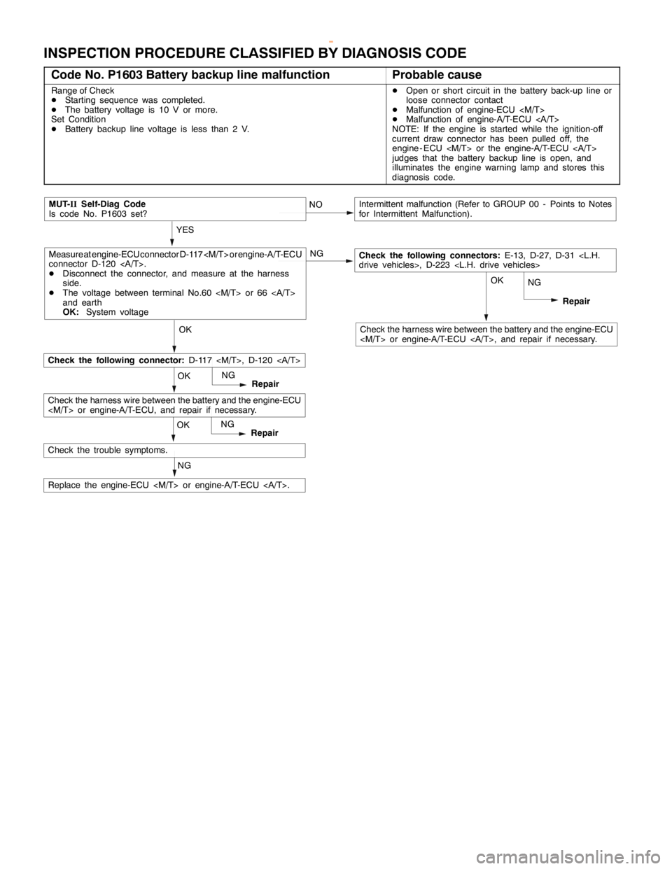
INSPECTION PROCEDURE CLASSIFIED BY DIAGNOSIS CODE
Code No. P1603 Battery backup line malfunctionProbable cause
Range of Check
DStarting sequence was completed.
DThe battery voltage is 10 V or more.
Set Condition
DBattery backup line voltage is less than 2 V.DOpen or short circuit in the battery back-up line or
loose connector contact
DMalfunction of engine-ECU
DMalfunction of engine-A/T-ECU
NOTE: If the engine is started while the ignition-off
current draw connector has been pulled off, the
engine - ECU
judges that the battery backup line is open, and
illuminates the engine warning lamp and stores this
diagnosis code.
NG
Replace the engine-ECU
Check the trouble symptoms.
OKNG
Repair
Check the harness wire between the battery and the engine-ECU
OKNG
Repair
Check the harness wire between the battery and the engine-ECU
OK
NG
Repair
MUT-IISelf-Diag Code
Is code No. P1603 set?
Check the following connector:D-117
Check the following connectors:E-13, D-27, D-31
connector D-120 .
DDisconnect the connector, and measure at the harness
side.
DThe voltage between terminal No.60
and earth
OK:System voltageNG
Intermittent malfunction (Refer to GROUP 00 - Points to Notes
for Intermittent Malfunction).
www.WorkshopManuals.co.uk
Purchased from www.WorkshopManuals.co.uk
Page 517 of 1839
DIESEL FUEL <4M4> -Troubleshooting13C-26
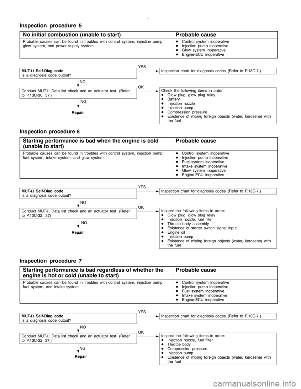
Inspection procedure 5
No initial combustion (unable to start)
Probable cause
Probable causes can be found in troubles with control system, injectionpump,
glow system, and power supply system.DControl system inoperative
DInjection pump inoperative
DGlow system inoperative
DEngine-ECU inoperative
NG
Repair
MUT-
IISelf-Diag code
Is a diagnosis code output?YESInspection chart for diagnosis codes (Refer to P.13C-7.)
NO
Conduct MUT-IIData list check and an actuator test. (Refer
to P.13C-30, 37.)OKCheck the following items in order:
DGlow plug, glowplugrelay
DBattery
DInjection nozzle
DInjection pump
DCompression pressure
DExistence of mixing foreign objects (water, kerosene) with
the fuel
Inspection procedure 6
Starting performance is bad when the engine is cold
(unable to start)
Probable cause
Probable causes can be found in troubles with control system, injectionpump,
fuel system, intake system, and glow system.DControl system inoperative
DInjection pump inoperative
DFuel system inoperative
DIntake system inoperative
DGlow system inoperative
DEngine-ECU inoperative
NG
Repair
MUT-
IISelf-Diag code
Is a diagnosis code output?YESInspection chart for diagnosis codes (Refer to P.13C-7.)
NO
Conduct MUT-IIData list check and an actuator test. (Refer
to P.13C-32, 37)OKInspect the following items in order:
DGlow plug, glowplugrelay
DInjection nozzle, fuel filter
DThrottle body assembly
DExistence of starter switch signal input
DEngine oil
DInjection pump
DExistence of mixing foreign objects (water, kerosene) with
the fuel
Inspection procedure 7
Starting performance is bad regardless of whether the
engine is hot or cold (unable to start)
Probable cause
Probable causes can be found in troubles with control system, injectionpump,
fuel system, and intake system.DControl system inoperative
DInjection pump inoperative
DFuel system inoperative
DIntake system inoperative
DEngine-ECU inoperative
NG
Repair
MUT-
IISelf-Diag code
Is a diagnosis code output?YESInspection chart for diagnosis codes (Refer to P.13C-7.)
NO
Conduct MUT-IIData list check and an actuator test. (Refer
to P.13C-32, 37.)OKInspect the following items in order:
DInjection nozzle, fuel filter
DThrottle body
DCompression pressure
DInjection pump
DExistence of mixing foreign objects (water, kerosene) with
the fuel
www.WorkshopManuals.co.uk
Purchased from www.WorkshopManuals.co.uk
Page 522 of 1839
DIESEL FUEL <4M4> -Troubleshooting13C-31
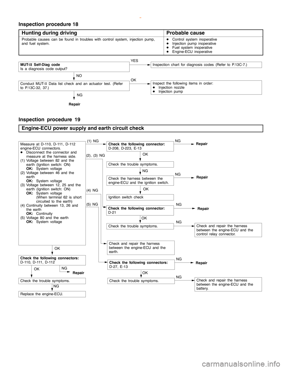
Inspection procedure 18
Hunting during driving
Probable cause
Probable causes can be found in troubles with control system, injectionpump,
and fuel system.DControl system inoperative
DInjection pump inoperative
DFuel system inoperative
DEngine-ECU inoperative
NG
Repair
MUT-
IISelf-Diag code
Is a diagnosis code output?YESInspection chart for diagnosis codes (Refer to P.13C-7.)
NO
Conduct MUT-IIData list check and an actuator test. (Refer
to P.13C-32, 37.)OKInspect the following items in order:
DInjection nozzle
DInjection pump
Inspection procedure 19
Engine-ECU power supply and earth circuit check
(5) NG
Check the trouble symptoms.
NG
Repair
(2), (3) NGOK
Check the trouble symptoms.
OK
NG
Check the harness between the
engine-ECU and the ignition switch.
Ignition switch check
(4) NG
Check and repair the harness
between the engine-ECU and the
earth.
OK
Check the following connectors:
D-110, D-111, D-112
NG
Replace the engine-ECU.
OK
Check the trouble symptoms.
Check the following connectors:
D-27, E-13Repair NG
NG
RepairCheck the following connector:
D-21
NG
Check and repair the harness
between the engine-ECU and the
control relay connector.
NG
Repair
OK
Check the trouble symptoms.NGCheck and repair the harness
between the engine-ECU and the
battery.
Check the following connector:
D-208, D-223, E-13NG
RepairMeasure at D-110, D-111, D-112
engine-ECU connectors.
DDisconnect the connector and
measure at the harness side.
(1) Voltage between 82 and the
earth (Ignition switch: ON)
OK:
System voltage
(2) Voltage between 46 and the
earth
OK:
System voltage
(3) Voltage between 12, 25 and the
earth (Ignition switch: ON)
OK:
System voltage
(When terminal 62 is short
circuited to theearth)
(4) Continuity between 13, 26 and
the earth
OK
:Continuity
(5) Voltage 80 and the earth
OK:
System voltage(1) NG
OK
www.WorkshopManuals.co.uk
Purchased from www.WorkshopManuals.co.uk
Page 528 of 1839

DIESEL FUEL <4M4> -Troubleshooting13C-37
ACTUATOR TEST TABLE
Item
No.Check itemDrive Con-
tentsInspection
conditionsValue to be determined
as normalCode No.
or inspec-
tion proce-
dure No.Reference
page
02Glow plug relayTurning theIgnition switch:Battery charge is––
relay from
OFF to ON orONenergized to the glow
plug when the glow
from ON to
OFFplug relay is ON.
03A/C compressorTurning theIgnition switch:The A/C compressor––
relayrelay from
OFF to ON orONclutch makes an
audible sound.
from ON to
OFF
11Timing control
valveTurn the
timing control
valve to ONDIgnition
switch: ON
DEngine:
IdlingMakes an audible
soundCode
No.4313C-20
12Turn the
timing control
valve to OFF
Idling
DTimer piston
position
sensor:
Normal
15Glow lampTurn the glow
lamp on or offIgnition switch:
ONThe glow lamp turns
on––
16Warning lampTurn the
warning lamp
on or offIgnition switch:
ONThe warning lamp
turns onProcedure
No.3, 413C-25
22Condenser fan
relayTurning the
relay from
OFF to ON or
from ON to
OFFIgnition switch:
ONThe condenser fan
rotates.––
23Main throttle
solenoid valveTurn the
solenoid
valve from
OFF to ON or
from ON to
OFFDIgnition
switch: ON
DVehicle
speed:
0 km/h
DEngine
speed:
1,000 r/min
or lowerMakes an audible
soundCode
No.4113C-19
24Sub throttle
solenoid valveTurn the
solenoid
valve from
OFF to ON or
from ON to
OFFDIgnition
switch: ON
DVehicle
speed:
0 km/h
DEngine
speed:
1,000 r/min
or lowerMakes an audible
sound––
www.WorkshopManuals.co.uk
Purchased from www.WorkshopManuals.co.uk
Page 595 of 1839

MITSUBISHI SC-Troubleshooting13E-6
INSPECTION CHART FOR DIAGNOSIS CODES
Diagnosis
code No.Diagnosis itemSC warning lampReference page
27*1SC-ECU power supply system (abnormal voltage drop)Flashes13E-6
51*2Vehicle speed sensor wheel speed sensor system (output
signal abnormality)Flashes13E-7
52Vehicle speed sensor system (open circuit or short-circuit)Flashes13E-8
53*2Wheel speed sensor system (open circuit or short-circuit)Flashes13E-8
55*2G sensor systemFlashes13E-9
71Communication line between the engine-ECU or engine-
A/T-ECU and the systemFlashes13E-10
72Engine-ECU or Engine-A/T-ECU systemIlluminates13E-10
74*2Communication line between the A/T-ECU and the system
<4M4-A/T>Flashes13E-11
81*1The SC - ECU is controlling the system too longFlashes13E-11
NOTE
*1: Code No.27 and 81 are erased from the memory if the condition returns to normal.
*2: For code Nos.51, 53, 55 and 74, a diagnosis code will be set in ten seconds after a failure is detected.
INSPECTION PROCEDURE FOR DIAGNOSIS CODE
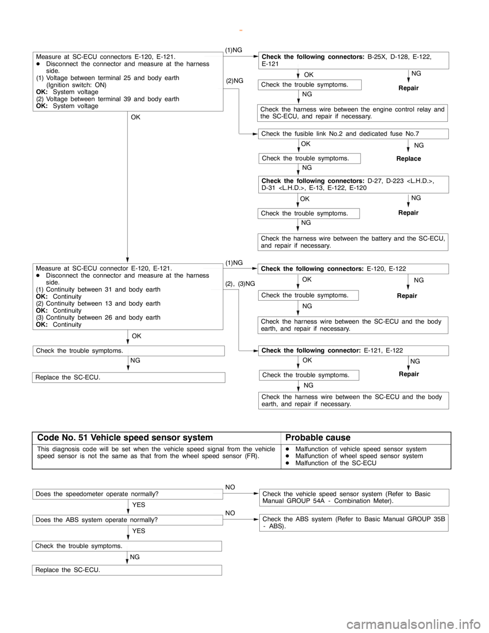
Code No. 27 SC-ECU power supply system (abnormal
voltage drop)Probable cause
This diagnosis code will be set if the SC-ECU power supply voltage drops below
a certain level.DMalfunction of battery
DMalfunction of harness or connector
DMalfunction of the SC-ECU
Caution
If the system voltage drops during inspection, this code will be output to indicate a current problem.
And correct problem diagnosis will not be possible. Before carrying out the following procedure,
check the battery and recharge it if necessary.
www.WorkshopManuals.co.uk
Purchased from www.WorkshopManuals.co.uk
Page 596 of 1839
MITSUBISHI SC-Troubleshooting MITSUBISHI SC-Troubleshooting13E-7
OK
NG
Repair
OK
Check the trouble symptoms.
NG
OKNG
Repair
OK
(1)NGCheck the following connectors:
B-25X, D-128, E-122,
E-121
NG
Check the harness wire between the engine control relay and
the SC-ECU, and repair if necessary. (2)NG
OK
Check the trouble symptoms.
NG
Replace
NG
Check the harness wire between the battery and the SC-ECU,
and repair if necessary.
Check the following connectors:
D-27, D-223
D-31
Measure at SC-ECU connectors E-120, E-121.
DDisconnect the connector and measure at the harness
side.
(1) Voltage between terminal 25 and body earth
(Ignition switch: ON)
OK:
System voltage
(2) Voltage between terminal 39 and body earth
OK:
System voltage
NG (1)NG
Check the harness wire between the SC-ECU and the body
earth, and repair if necessary.
Repair
NG
Replace the SC-ECU.
Check the trouble symptoms.
Check the following connectors:
E-120, E-122
NG
(2), (3)NG
Check the harness wire between the SC-ECU and the body
earth, and repair if necessary.
OK
NG
Repair
NGCheck the trouble symptoms.
Check the following connector:
E-121, E-122
OK
Check the trouble symptoms.
Measure at SC-ECU connector E-120, E-121.
DDisconnect the connector and measure at the harness
side.
(1) Continuity between 31 and body earth
OK:
Continuity
(2) Continuity between 13 and body earth
OK:
Continuity
(3) Continuity between 26 and body earth
OK:
Continuity
Check the trouble symptoms.
Check the fusible link No.2 and dedicated fuse No.7
Code No. 51 Vehicle speed sensor systemProbable cause
This diagnosis code will be set when the vehicle speed signal from the vehicle
speed sensor is not the same as that from the wheel speed sensor (FR).DMalfunction of vehicle speed sensor system
DMalfunction of wheel speed sensor system
DMalfunction of the SC-ECU
NG
Check the trouble symptoms.
Replace the SC-ECU.YES
NOCheck the vehicle speed sensor system (Refer to Basic
Manual GROUP 54A - Combination Meter).Does the speedometer operate normally?
YES
NOCheck the ABS system (Refer to Basic Manual GROUP 35B
- ABS).Does the ABS system operate normally?
www.WorkshopManuals.co.uk
Purchased from www.WorkshopManuals.co.uk
Page 601 of 1839
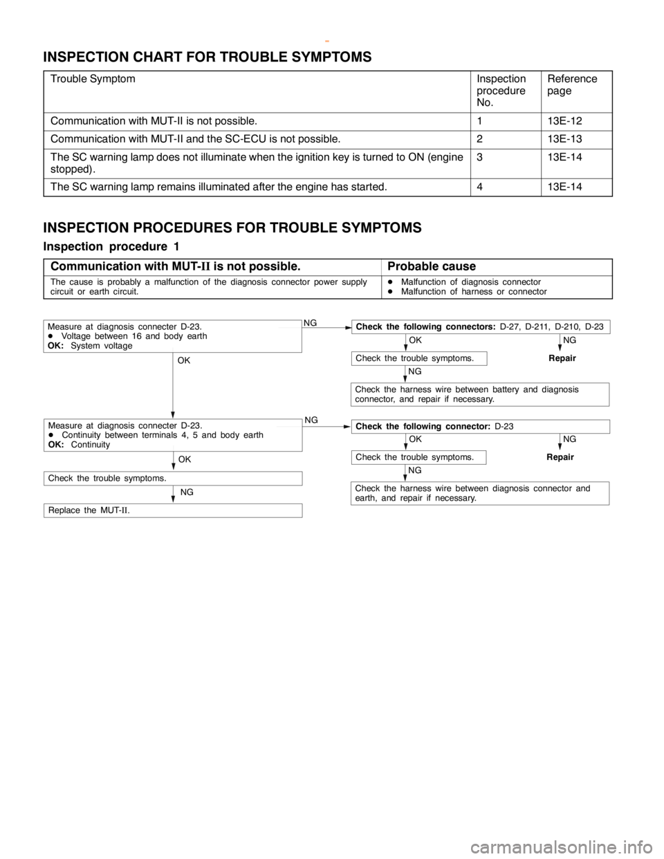
MITSUBISHI SC-Troubleshooting13E-12
INSPECTION CHART FOR TROUBLE SYMPTOMS
Trouble SymptomInspection
procedure
No.Reference
page
Communication with MUT-II is not possible.113E-12
Communication with MUT-II and the SC-ECU is not possible.213E-13
The SC warning lamp does not illuminate when the ignition key is turned to ON (engine
stopped).313E-14
The SC warning lamp remains illuminated after the engine has started.413E-14
INSPECTION PROCEDURES FOR TROUBLE SYMPTOMS
Inspection procedure 1
Communication with MUT-
IIis not possible.
Probable cause
The cause is probably a malfunction of the diagnosis connector power supply
circuit or earth circuit.DMalfunction of diagnosis connector
DMalfunction of harness or connector
NGCheck the following connectors:
D-27, D-211, D-210, D-23
NG
Repair
OK
Check the trouble symptoms.
NG
Check the harness wire between battery and diagnosis
connector, and repair if necessary.
OK
NG
NG
Repair
OK
Check the trouble symptoms.
NG
Check the harness wire between diagnosis connector and
earth, and repair if necessary.
OK
NG
Replace the MUT-
II.
Measure at diagnosis connecter D-23.
DVoltage between 16 and body earth
OK:
System voltage
Check the following connector:
D-23Measure at diagnosis connecter D-23.
DContinuity between terminals 4, 5 and body earth
OK:
Continuity
Check the trouble symptoms.
www.WorkshopManuals.co.uk
Purchased from www.WorkshopManuals.co.uk