2000 MITSUBISHI MONTERO ESP
[x] Cancel search: ESPPage 944 of 1839

Page 957 of 1839

Page 964 of 1839

Page 984 of 1839

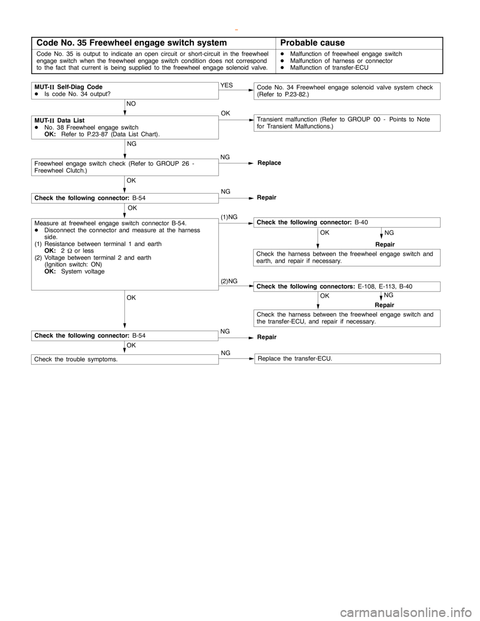
AUTOMATIC TRANSMISSION -Troublehshooting
Code No. 35 Freewheel engage switch systemProbable cause
Code No. 35 is output to indicate anopencircuit or short-circuit in the freewheel
engageswitch when the freewheelengageswitch condition does not correspond
to the fact that current isbeing supplied to the freewheel engage solenoidvalve.DMalfunction of freewheel engageswitch
DMalfunction of harness or connector
DMalfunction of transfer-ECU
NG
(1)NG
MUT-
IIData List
DNo. 38 Freewheel engageswitch
OK:Refer to P.23-87 (Data List Chart).Transient malfunction (Refer to GROUP 00 - Points to Note
for Transient Malfunctions.) OK
OK OK OKNG
Repair
Check the following connector:B-40
Check the harness between the freewheelengageswitch and
earth, and repair if necessary.
OK
OK
Check the trouble symptoms.Replace the transfer-ECU.
Measure at freewheel engageswitch connector B-54.
DDisconnect the connector and measure at the harness
side.
(1) Resistance between terminal 1 and earth
OK:2
Wor less
(2) Voltage between terminal 2 and earth
(Ignition switch: ON)
OK:System voltageNG
Replace
NG
Repair
Freewheel engageswitch check (Refer to GROUP 26 -
Freewheel Clutch.)
Check the following connector:B-54
MUT-
IISelf-Diag Code
DIs code No. 34 output?Code No. 34 Freewheelengage solenoidvalve system check
(Refer to P.23-82.) YES
NO
NG
(2)NG
NG
OK
Repair
Check the following connectors:E-108, E-113, B-40
Check the harness between the freewheelengageswitch and
the transfer-ECU, and repair if necessary.
Check the following connector:B-54Repair
NG
www.WorkshopManuals.co.uk
Purchased from www.WorkshopManuals.co.uk
Page 989 of 1839

AUTOMATIC TRANSMISSION -Troubleshooting
Item
No.Normal condition Inspection conditions Check item
21Ignition switchIgnition switch: ONON
Ignition switch: OFFOFF
22Transmission identi-
ficationVehicles with A/TA/T
23Stop lamp switchIgnition switch: ONBrake pedal: DepressedON
Engine: StoppedBrake pedal: ReleasedOFF
24Transfer leverTransfer shift lever position: 2HON
switch 2HTransfer shift lever position: Other than the aboveOFF
25Transfer leverTransfer shift lever position: 4HON
switch 4HTransfer shift lever position: Other than the aboveOFF
26Transfer leverTransfer shift lever position: 4HLcON
switch 4HLcTransfer shift lever position: Other than the aboveOFF
27Transfer leverTransfer shift lever position: 4LLcON
switch 4LLcTransfer shift lever position: Other than the aboveOFF
28Engine identificationPetrol vehiclesPETROL
Diesel vehiclesDIESEL
30Freewheel engageDuring 2WDON
solenoid valveDuring 4WDOFF
31Inhibitor switch NSelector lever position: NON
Selector lever position: Other than the aboveOFF
32Inhibitor switch PSelector lever position: PON
Selector lever position: Other than the aboveOFF
332WD switchDriving conditions: 2WD (2H)ON
Driving conditions: Other than the aboveOFF
342WD/4WD switchDriving conditions: 2WD (2H), 4WD (4H)ON
Driving conditions: Other than the aboveOFF
354H switchDriving conditions: 4WD (4H), 4WD (4HLc)ON
Driving conditions: Other than the aboveOFF
36Center differentialDriving conditions: 4WD (4HLc), 4WD (4LLc)ON
lock switchDriving conditions: Other than the aboveOFF
374LLc switchDriving conditions: 4WD (4LLc)ON
Driving conditions: Other than the aboveOFF
38Freewheel engageDuring 2WDOFF
switchDuring 4WDON
www.WorkshopManuals.co.uk
Purchased from www.WorkshopManuals.co.uk
Page 1270 of 1839

ABS <4WD> -Troubleshooting35B-7
INSPECTION CHART FOR DIAGNOSIS CODES
Diagnosis code
No.Diagnosis itemReference page
11Wheel speed sensor (FR) system (open circuit or short - circuit)35B-8
12Wheel speed sensor (FL) system (open circuit or short - circuit)35B-8
13Wheel speed sensor (RR) system (open circuit or short - circuit)35B-8
14Wheel speed sensor (RL) system (open circuit or short - circuit)35B-8
15Wheel speed sensor system (output signal abnormality)35B-9
16ABS-ECU or valve relay power supply system (abnormal voltage
drop or rise)35B-10
21Wheel speed sensor (FR) system35B-8
22Wheel speed sensor (FL) system35B-8
23Wheel speed sensor (RR) system35B-8
24Wheel speed sensor (RL) system35B-8
26Center differential lock switch system35B-11, 12
27Rear differential lock switch system35B-11, 12
32G sensor system35B-13
33Stop lamp switch system35B-14
41Control solenoid valve (FR)
systemIf there is no response to the
solenoid valve drive signal35B-15
42Control solenoid valve (FL)
systemcorresponding to each respec-
tive item
43Control solenoid valve (RR)
system
44Control solenoid valve (RL)
system
45Changeover solenoid valve
(FR) system
46Changeover solenoid valve
(FL) system
51Valve relay system (ON problem)35B-16
52Valve relay system(OFFproblem)35B-17
55HBB systemCarry out HBB troubleshoot-
ing. (Refer to GROUP 35A.)
63ABS-ECU system35B-32 (ABS-ECU replace-
ment)
NOTE
*: Code No.16 is erased from the memory if the condition returns to normal.
www.WorkshopManuals.co.uk
Purchased from www.WorkshopManuals.co.uk
Page 1285 of 1839

ABS <4WD> -Troubleshooting35B-22
DATA LIST REFERENCE TABLE
The following ECU input data items can be read using the MUT-II
.
(1) When system is normal
Item
No.Check itemInspection conditionsNormal condi-
tion
11Front - right wheel
speedWhen vehicle is being drivenSpeedometer
display and
12Front - left wheel
speedMUT-IIdisplay
are identical.
13Rear - right wheel
speed
14Rear - left wheel
speed
16System voltageIgnition switch: ON6.5 - 22.3 V
26Center differential
lock switchIgnition switch: ONTransfer selector lever position:
2H, 4HOFF
Transfer selector lever position:
4HLc, 4LLcON
27Rear differential lock
switchIgnition switch: ONOFF
32G sensorD
Ignition switch: ON
D
When vehicle is stationary (level)2.4 - 2.6 V
When vehicle is being driven1.0 - 4.0 V
33Stop lampIgnition switch: ONWhen brake pedal is depressedON
SwitchWhen brake pedal is releasedOFF
(2) When system is interrupted by the ECU
When the diagnosis function has caused the operation of the ABS-ECU to be stopped, the
MUT-II
display data may be different from the actual condition.
ACTUATOR TEST TABLE
The following actuators can be force-driven using the MUT-II
.
NOTE
(1) Actuator tests cannot be carried out when the operation of the ABS-ECU has been stopped by
the fail-safe function.
(2) Actuator tests can only be carried out while the vehicle is stopped.
ACTUATOR TEST SPECIFICATIONS
Item No.Check itemDrive Contents
01FR wheel solenoid valveHBB select solenoid valves and control solenoid valves for the
02FL wheel solenoid valverespective channel
03RR wheel solenoid valve
04RL wheel solenoid valve
27Air bleeding (1)HBB select solenoid valves and control solenoid valve OUT (FR, FL)
28Air bleeding (2)HBB control solenoid valve OUT (RR, RL)
www.WorkshopManuals.co.uk
Purchased from www.WorkshopManuals.co.uk
Page 1310 of 1839

37A-1
STEERING
CONTENTS
GENERAL INFORMATION 2..................
SERVICE SPECIFICATIONS 5.................
LUBRICANTS 5..............................
SEALANT AND ADHESIVE 5.................
SPECIAL TOOLS 6..........................
ON-VEHICLE SERVICE 8.....................
Steering Wheel Free Play Check 8..............
Steering Angle Check 8........................
Tie Rod End Ball Joint Starting Torque Check 8..
Stationary Steering Effort Check 9...............
Steering Wheel Returnability Check 9............
Oil Pump Belt Tension Check <6G7,4D5> 9......Power Steering Fluid Level Check 10............
Power Steering Fluid Replacement 10...........
Power Steering System Bleeding 10.............
Oil Pump Pressure Test 11.....................
Power Steering Oil Pressure Switch Check
<6G7,4M4> 12.................................
Ball Joint Dust Cover Check 12.................
STEERING WHEEL AND SHAFT* 13.........
POWER STEERING GEAR BOX AND
LINKAGE 16................................
POWER STEERING OIL PUMP 30...........
POWER STEERING OIL HOSES 35..........
WARNINGS REGARDING SERVICING OF SUPPLEMENTAL RESTRAINT SYSTEM (SRS) EQUIPPED VEHICLES
WARNING!
(1) Improper service or maintenance of any component of the SRS, or any SRS-related component, can lead to personal
injury or death to service personnel (from inadvertent firing of the air bag) or to the driver and passenger (from rendering
the SRS inoperative).
(2) Service or maintenance of any SRS component or SRS-related component must be performed only at an authorized
MITSUBISHI dealer.
(3) MITSUBISHI dealer personnel must thoroughly review this manual, and especially its GROUP 52B - Supplemental
Restraint System (SRS) before beginning any service or maintenance of any component of the SRS or any SRS-related
component.
NOTE
The SRS includes the following components: SRS-ECU, SRS warning lamp, air bag module, clock spring and interconnecting
wiring. Other SRS-related components (that mayhave to be removed/installed in connectionwith SRS service or maintenance) are
indicated in the table of contents by an asterisk(*).
www.WorkshopManuals.co.uk
Purchased from www.WorkshopManuals.co.uk