2000 MITSUBISHI MONTERO ECU
[x] Cancel search: ECUPage 981 of 1839
AUTOMATIC TRANSMISSION -Troublehshooting
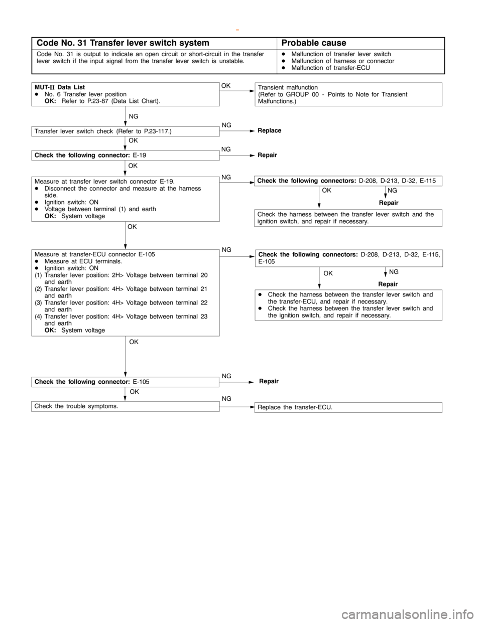
Code No. 31 Transfer lever switch systemProbable cause
Code No. 31 is output to indicate anopencircuit or short-circuit in the transfer
lever switch if the input signal from the transfer lever switch is unstable.DMalfunction of transfer lever switch
DMalfunction of harness or connector
DMalfunction of transfer-ECU
NG
NG
MUT-
IIData List
DNo. 6 Transfer lever position
OK:Refer to P.23-87 (Data List Chart).Transient malfunction
(Refer to GROUP 00 - Points to Note for Transient
Malfunctions.) OK
OK OKOKNG
DCheck the harness between the transfer lever switch and
the transfer-ECU, and repair if necessary.
DCheck the harness between the transfer lever switch and
the ignition switch, and repair if necessary.Repair
Check the harness between the transfer lever switch and the
ignition switch, and repair if necessary.
OK OK
NG
OK
OK
NG
NG
Check the trouble symptoms.Replace the transfer-ECU.
Measure at transfer-ECU connector E-105
DMeasure at ECU terminals.
DIgnition switch: ON
(1) Transfer lever position: 2H> Voltage between terminal 20
and earth
(2) Transfer lever position: 4H> Voltage between terminal 21
and earth
(3) Transfer lever position: 4H> Voltage between terminal 22
and earth
(4) Transfer lever position: 4H> Voltage between terminal 23
and earth
OK:System voltage
Measure at transfer lever switch connector E-19.
DDisconnect the connector and measure at the harness
side.
DIgnition switch: ON
DVoltage between terminal (1) and earth
OK:System voltageNG
Replace
NG
Repair
Transfer lever switch check (Refer to P.23-117.)
Check the following connector:E-19
Repair NG
Check the following connector:E-105Repair
Check the following connectors:D-208, D-213, D-32, E-115,
E-105
Check the following connectors:D-208, D-213, D-32, E-115
www.WorkshopManuals.co.uk
Purchased from www.WorkshopManuals.co.uk
Page 982 of 1839
AUTOMATIC TRANSMISSION -Troublehshooting
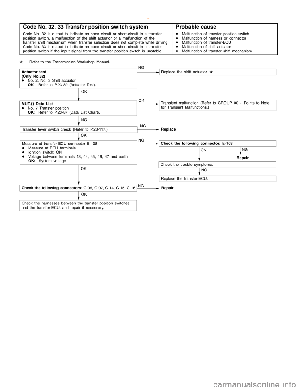
Code No. 32, 33 Transfer position switch systemProbable cause
Code No. 32 is output to indicate anopencircuit or short-circuit in a transfer
position switch, a malfunction of the shift actuator or a malfunction of the
transfer shift mechanism when transfer selection does not complete while driving.
Code No. 33 is output to indicate anopencircuit or short-circuit in a transfer
position switch if the input signal from the transfer position switch is unstable.DMalfunction of transfer position switch
DMalfunction of harness or connector
DMalfunction of transfer-ECU
DMalfunction of shift actuator
DMalfunction of transfer shift mechanism
LRefer to the Transmission Workshop Manual.
OK
Transient malfunction (Refer to GROUP 00 - Points to Note
for Transient Malfunctions.)
OKNG
Check the harnesses between the transfer position switches
and the transfer-ECU, and repair if necessary.OKNG
OK
OK
NG
Replace the transfer-ECU. NG
ReplaceTransfer lever switch check (Refer to P.23-117.)
Repair NG
Repair
Check the trouble symptoms.
NG OK
Replace the shift actuator.
L
MUT-
IIData List
DNo. 7 Transfer position
OK:Refer to P.23-87 (Data List Chart).
NG
Actuator test
(Only No.32)
DNo. 2, No. 3 Shift actuator
OKRefer to P.23-89 (Actuator Test).
Measure at transfer-ECU connector E-108
DMeasure at ECU terminals.
DIgnition switch: ON
DVoltage between terminals 43, 44, 45, 46, 47 and earth
OK:System voltage
Check the following connectors:C-06, C-07, C-14, C-15, C-16
Check the following connector:E-108
www.WorkshopManuals.co.uk
Purchased from www.WorkshopManuals.co.uk
Page 983 of 1839
AUTOMATIC TRANSMISSION -Troublehshooting
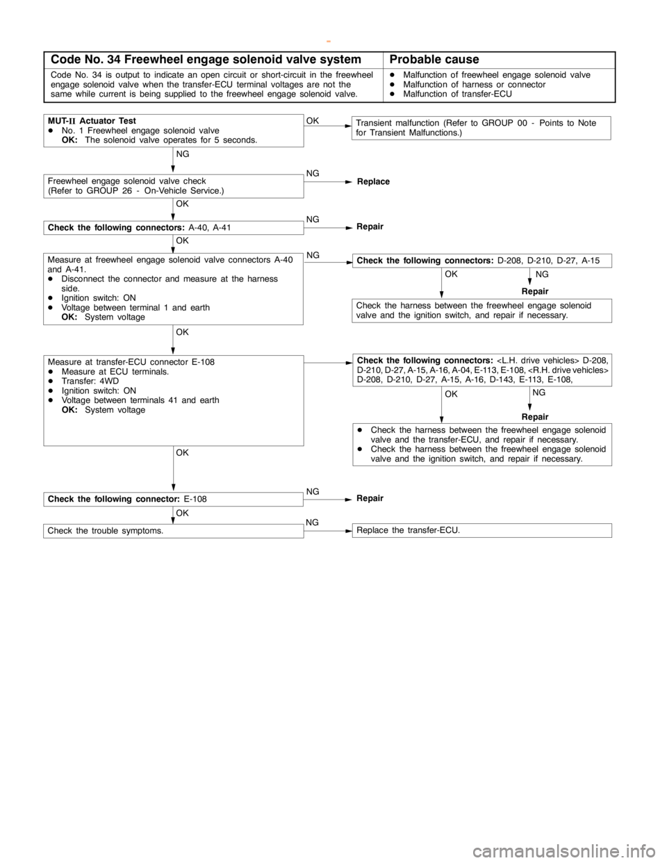
Code No. 34 Freewheel engage solenoid valve systemProbable cause
Code No. 34 is output to indicate anopencircuit or short-circuit in the freewheel
engage solenoidvalve when the transfer-ECU terminal voltages are not the
same while current isbeing supplied to the freewheel engage solenoidvalve.DMalfunction of freewheel engage solenoidvalve
DMalfunction of harness or connector
DMalfunction of transfer-ECU
NG
NG
MUT-
IIActuator Test
DNo. 1 Freewheel engage solenoidvalve
OK:The solenoid valve operates for 5 seconds.Transient malfunction (Refer to GROUP 00 - Points to Note
for Transient Malfunctions.) OK
OK OK OKNG
DCheck the harness between the freewheelengage solenoid
valve and the transfer-ECU, and repair if necessary.
DCheck the harness between the freewheelengage solenoid
valve and the ignition switch, and repair if necessary.Repair
Check the harness between the freewheelengage solenoid
valve and the ignition switch, and repair if necessary.
OK OK
OK
NG
Check the trouble symptoms.Replace the transfer-ECU.
Measure at transfer-ECU connector E-108
DMeasure at ECU terminals.
DTransfer: 4WD
DIgnition switch: ON
DVoltage between terminals 41 and earth
OK:System voltage
Measure at freewheel engage solenoidvalve connectors A-40
and A-41.
DDisconnect the connector and measure at the harness
side.
DIgnition switch: ON
DVoltage between terminal 1 and earth
OK:System voltageNG
Replace
NG
Repair
Freewheel engage solenoidvalve check
(Refer to GROUP 26 - On-Vehicle Service.)
Check the following connectors:A-40, A-41
Repair NG
Check the following connector:E-108
NG
Repair
OK
Check the following connectors:
D-210, D-27, A-15, A-16, A-04, E-113, E-108,
D-208, D-210, D-27, A-15, A-16, D-143, E-113, E-108,
Check the following connectors:D-208, D-210, D-27, A-15
www.WorkshopManuals.co.uk
Purchased from www.WorkshopManuals.co.uk
Page 984 of 1839
AUTOMATIC TRANSMISSION -Troublehshooting
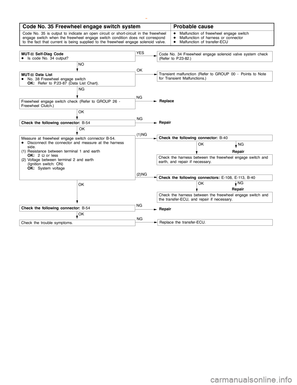
Code No. 35 Freewheel engage switch systemProbable cause
Code No. 35 is output to indicate anopencircuit or short-circuit in the freewheel
engageswitch when the freewheelengageswitch condition does not correspond
to the fact that current isbeing supplied to the freewheel engage solenoidvalve.DMalfunction of freewheel engageswitch
DMalfunction of harness or connector
DMalfunction of transfer-ECU
NG
(1)NG
MUT-
IIData List
DNo. 38 Freewheel engageswitch
OK:Refer to P.23-87 (Data List Chart).Transient malfunction (Refer to GROUP 00 - Points to Note
for Transient Malfunctions.) OK
OK OK OKNG
Repair
Check the following connector:B-40
Check the harness between the freewheelengageswitch and
earth, and repair if necessary.
OK
OK
Check the trouble symptoms.Replace the transfer-ECU.
Measure at freewheel engageswitch connector B-54.
DDisconnect the connector and measure at the harness
side.
(1) Resistance between terminal 1 and earth
OK:2
Wor less
(2) Voltage between terminal 2 and earth
(Ignition switch: ON)
OK:System voltageNG
Replace
NG
Repair
Freewheel engageswitch check (Refer to GROUP 26 -
Freewheel Clutch.)
Check the following connector:B-54
MUT-
IISelf-Diag Code
DIs code No. 34 output?Code No. 34 Freewheelengage solenoidvalve system check
(Refer to P.23-82.) YES
NO
NG
(2)NG
NG
OK
Repair
Check the following connectors:E-108, E-113, B-40
Check the harness between the freewheelengageswitch and
the transfer-ECU, and repair if necessary.
Check the following connector:B-54Repair
NG
www.WorkshopManuals.co.uk
Purchased from www.WorkshopManuals.co.uk
Page 985 of 1839
AUTOMATIC TRANSMISSION -Troublehshooting
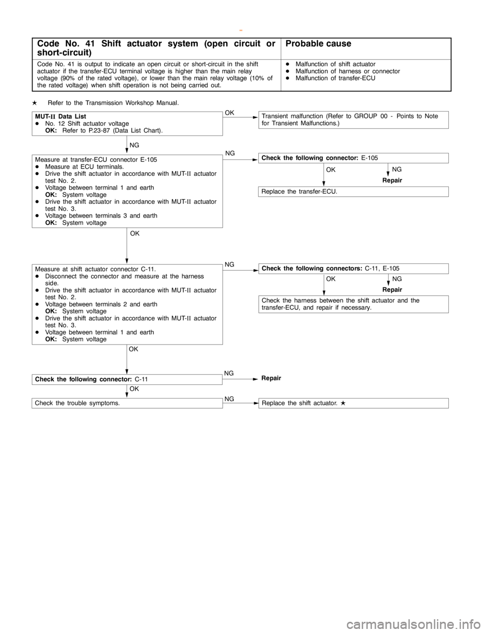
Code No. 41 Shift actuator system (open circuit or
short-circuit)Probable cause
Code No. 41 is output to indicate anopencircuit or short-circuit in the shift
actuator if the transfer-ECU terminal voltage is higher than themainrelay
voltage (90% of the rated voltage), or lower than themainrelay voltage (10% of
the rated voltage) when shift operation is notbeingcarried out.DMalfunction of shift actuator
DMalfunction of harness or connector
DMalfunction of transfer-ECU
LRefer to the Transmission Workshop Manual.
NG
NG
NG
MUT-
IIData List
DNo. 12 Shift actuator voltage
OK:Refer to P.23-87 (Data List Chart).Transient malfunction (Refer to GROUP 00 - Points to Note
for Transient Malfunctions.) OK
OK NG
Check the harness between the shift actuator and the
transfer-ECU, and repair if necessary.Repair
OKOK
OK
OK
NG
NG
Replace the transfer-ECU.
Check the following connectors:C-11, E-105Measure at shift actuator connector C-11.
DDisconnect the connector and measure at the harness
side.
DDrive the shift actuator in accordance with MUT-
IIactuator
test No. 2.
DVoltage between terminals 2 and earth
OK:System voltage
DDrive the shift actuator in accordance with MUT-
IIactuator
test No. 3.
DVoltage between terminal 1 and earth
OK:System voltage
Measure at transfer-ECU connector E-105
DMeasure at ECU terminals.
DDrive the shift actuator in accordance with MUT-
IIactuator
test No. 2.
DVoltage between terminal 1 and earth
OK:System voltage
DDrive the shift actuator in accordance with MUT-
IIactuator
test No. 3.
DVoltage between terminals 3 and earth
OK:System voltage
Repair NG
Check the following connector:C-11Repair
Replace the shift actuator.
L
Check the following connector:E-105
Check the trouble symptoms.
www.WorkshopManuals.co.uk
Purchased from www.WorkshopManuals.co.uk
Page 986 of 1839
AUTOMATIC TRANSMISSION -Troublehshooting
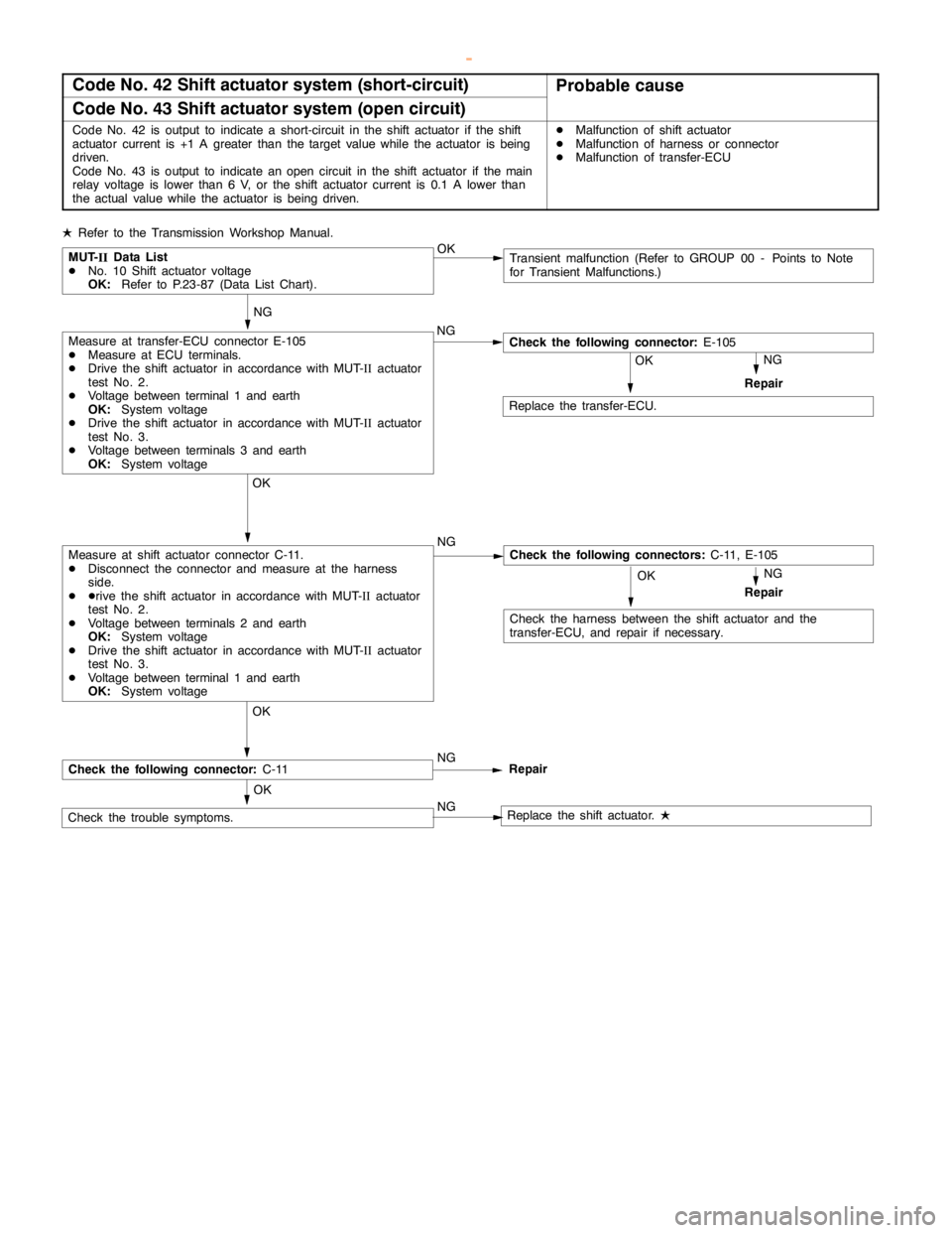
Code No. 42 Shift actuator system (short-circuit)Probable cause
Code No. 43 Shift actuator system (open circuit)
Code No. 42 is output to indicate a short-circuit in the shift actuator if the shift
actuator current is +1 A greater than the target value while the actuator isbeing
driven.
Code No. 43 is output to indicate anopencircuit in the shift actuator if themain
relay voltage is lower than 6 V, or the shift actuator current is 0.1 A lower than
the actual value while the actuator isbeing driven.DMalfunction of shift actuator
DMalfunction of harness or connector
DMalfunction of transfer-ECU
LRefer to the Transmission Workshop Manual.
NG
NG
MUT-
IIData List
DNo. 10 Shift actuator voltage
OK:Refer to P.23-87 (Data List Chart).Transient malfunction (Refer to GROUP 00 - Points to Note
for Transient Malfunctions.) OK
OK NG
Check the harness between the shift actuator and the
transfer-ECU, and repair if necessary.Repair
Check the following connector:E-105
OK OK
NG
OK
OK
NG
NG
Check the trouble symptoms.
Replace the transfer-ECU.
Check the following connectors:C-11, E-105Measure at shift actuator connector C-11.
DDisconnect the connector and measure at the harness
side.
DDrive the shift actuator in accordance with MUT-
IIactuator
test No. 2.
DVoltage between terminals 2 and earth
OK:System voltage
DDrive the shift actuator in accordance with MUT-
IIactuator
test No. 3.
DVoltage between terminal 1 and earth
OK:System voltage
Measure at transfer-ECU connector E-105
DMeasure at ECU terminals.
DDrive the shift actuator in accordance with MUT-
IIactuator
test No. 2.
DVoltage between terminal 1 and earth
OK:System voltage
DDrive the shift actuator in accordance with MUT-
IIactuator
test No. 3.
DVoltage between terminals 3 and earth
OK:System voltage
Repair NG
Check the following connector:C-11Repair
Replace the shift actuator.
L
www.WorkshopManuals.co.uk
Purchased from www.WorkshopManuals.co.uk
Page 987 of 1839
AUTOMATIC TRANSMISSION -Troublehshooting
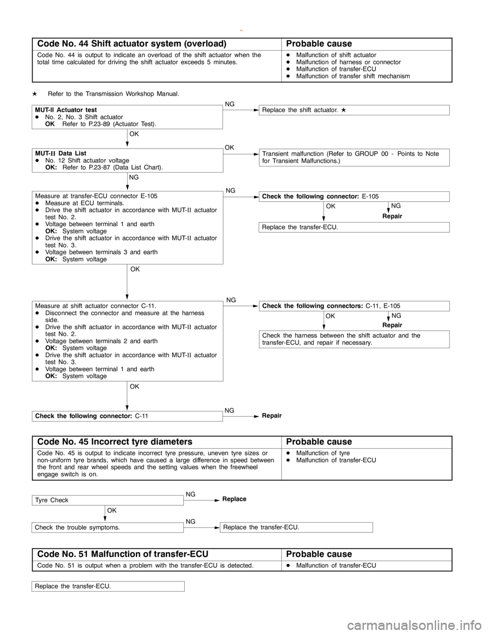
Code No. 44 Shift actuator system (overload)Probable cause
Code No. 44 is output to indicate an overload of the shift actuator when the
total time calculated for driving the shift actuator exceeds 5 minutes.DMalfunction of shift actuator
DMalfunction of harness or connector
DMalfunction of transfer-ECU
DMalfunction of transfer shift mechanism
LRefer to the Transmission Workshop Manual.
NG
NG
MUT-
IIData List
DNo. 12 Shift actuator voltage
OK:Refer to P.23-87 (Data List Chart).Transient malfunction (Refer to GROUP 00 - Points to Note
for Transient Malfunctions.) OK
OK NG
Check the harness between the shift actuator and the
transfer-ECU, and repair if necessary.Repair
Check the following connector:E-105
OK
NG
OK
OK
NG
Replace the transfer-ECU.
Check the following connectors:C-11, E-105Measure at shift actuator connector C-11.
DDisconnect the connector and measure at the harness
side.
DDrive the shift actuator in accordance with MUT-
IIactuator
test No. 2.
DVoltage between terminals 2 and earth
OK:System voltage
DDrive the shift actuator in accordance with MUT-
IIactuator
test No. 3.
DVoltage between terminal 1 and earth
OK:System voltage
Measure at transfer-ECU connector E-105
DMeasure at ECU terminals.
DDrive the shift actuator in accordance with MUT-
IIactuator
test No. 2.
DVoltage between terminal 1 and earth
OK:System voltage
DDrive the shift actuator in accordance with MUT-
IIactuator
test No. 3.
DVoltage between terminals 3 and earth
OK:System voltage
Repair NG
Check the following connector:C-11Repair
MUT-II Actuator test
DNo. 2, No. 3 Shift actuator
OKRefer to P.23-89 (Actuator Test).
OKNGReplace the shift actuator.
L
Code No. 45 Incorrect tyre diametersProbable cause
Code No. 45 is output to indicate incorrect tyre pressure, uneven tyre sizes or
non-uniform tyre brands, which have caused a large difference in speed between
the front and rear wheel speeds and the setting values when the freewheel
engageswitch is on.DMalfunction of tyre
DMalfunction of transfer-ECU
NG
Replace
Replace the transfer-ECU. NGCheck the trouble symptoms.
OK
Tyre Check
Code No. 51 Malfunction of transfer-ECUProbable cause
Code No. 51 is output when a problem with the transfer-ECU is detected.DMalfunction of transfer-ECU
Replace the transfer-ECU.
www.WorkshopManuals.co.uk
Purchased from www.WorkshopManuals.co.uk
Page 995 of 1839
O
N-V EH IC LE SER VIC E
B ASIC ADJU STM EN T PR O CED URES
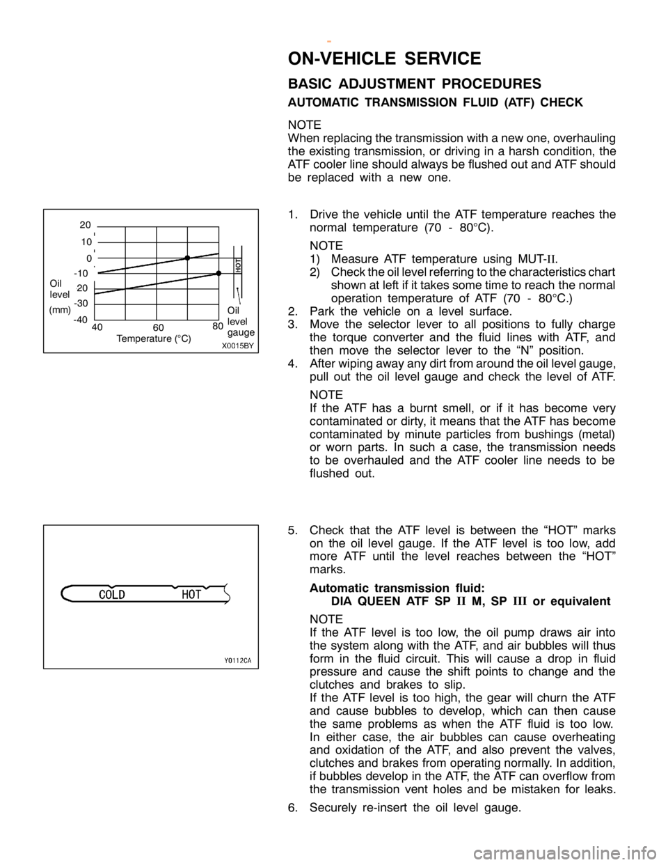
A UTO M ATIC TR ANSM IS SIO N FLU ID (A TF) CHEC K
N O TE
W hen re pla cin g th e tr a nsm is sio n wit h anew one,o ve rh aulin g
t h e exis tin g tr a nsm is sio n, or driv in g in ahars h co ndit io n, th e
A T F co ole r lin e sh ould alw ays be flu sh ed outa nd AT F sh ould
b e re pla ce d wit h a new one.
1 . Driv e th e ve hic le until th e AT F te m pera tu re re ach es th e
n orm al te m pera tu re (7 0 -80
°C
).
N O TE
1 ) Measu re AT F te m pera tu re usin g MUT-I
I
.
2 ) Check th e oil le ve lre fe rrin g to th e ch ara cte ris tic s ch art
s h ow n atle ft if it ta ke s so m etim eto re ach th e norm al
o pera tio n te m pera tu re of AT F (7 0 -80
°C
.)
2 . Park th e ve hic le on ale ve l su rfa ce .
3 . Move th e se le cto r le ve r to all posit io ns to fu lly ch arg e
t h e to rq ue co nve rte r and th e flu id lin es wit h AT F, and
t h en move th e se le cto r le ve r to th e “N ” posit io n.
4 . Afte r w ip in g aw ay any dir t fr o m aro und th e oil le ve lg auge,
p ull out th e oil le ve l gauge and ch eck th e le ve l of AT F.
N O TE
I f th e AT F has a burn t sm ell, or if it has beco m e ve ry
c o nta m in ate d or dir ty , it m eans th at th e AT F has beco m e
c o nta m in ate d by min ute partic le s fr o m bush in gs (m eta l)
o r worn parts . In su ch a ca se , th e tr a nsm is sio n needs
t o be ove rh aule d and th e AT F co ole r lin e needs to be
f lu sh ed out.
5 . Check th at th e AT F le ve l is betw een th e “H O T” m ark s
o n th e oil le ve l gauge. If th e AT F le ve l is to o lo w , add
m ore AT F until th e le ve l re ach es betw een th e “H O T”
m ark s.
A uto m atic tr a n sm is sio n flu id :
D IA QUEEN ATF SP I
I
M,SP I
II
or eq uiv ale n t
N O TE
I f th e AT F le ve l is to o lo w , th e oil pum p dra w s air in to
t h e syste m alo ng wit h th e AT F, and air bubble s will th us
f o rm in th e flu id cir c u it . This will ca use a dro p in flu id
p re ssu re and ca use th e sh if t poin ts to ch ange and th e
c lu tc h es and bra ke s to slip .
I f th e AT F le ve l is to o hig h, th e gear will ch urn th e AT F
a nd ca use bubble s to deve lo p, whic h ca n th en ca use
t h e sa m e pro ble m s as when th e AT F flu id is to o lo w .
I n eit h er ca se , th e air bubble s ca n ca use ove rh eatin g
a nd oxid atio n of th e AT F, and als o pre ve nt th e va lv e s,
c lu tc h es and bra ke s fr o m opera tin g norm ally . In addit io n,
i f bubble s deve lo p in th e AT F, th e AT F ca n ove rflo w fr o m
t h e tr a nsm is sio n ve nt hole s and be mis ta ke n fo r le aks.
6 . Secu re ly re -in se rt th e oil le ve l gauge. 0
(
m m) -
3 0
40
-
2 0 -
1 0 1
0 T
e m pera tu re (
° C
) 6
0 2
0 O
il
l e ve l
-4 0
80