2000 MITSUBISHI MONTERO ECU
[x] Cancel search: ECUPage 1277 of 1839
ABS <4WD> -Troubleshooting35B-14
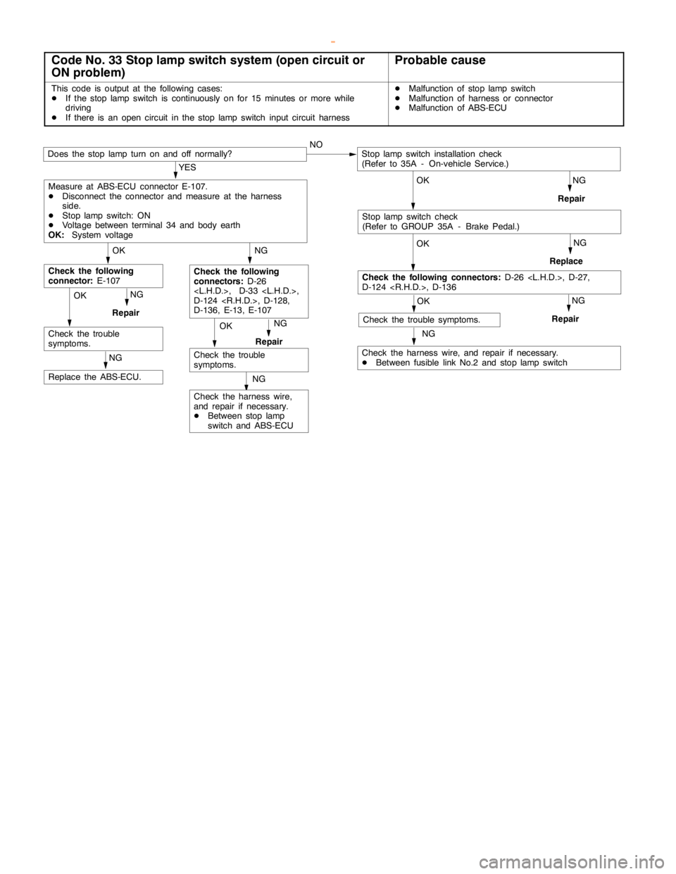
Code No. 33 Stop lamp switch system (open circuit or
ON problem)Probable cause
This code is output at the following cases:
DIf the stoplampswitch is continuously on for 15 minutes or more while
driving
DIf there is an opencircuit in the stoplampswitch input circuit harnessDMalfunction of stoplampswitch
DMalfunction of harness or connector
DMalfunction of ABS-ECU
OK
NG
Check the harness wire,
and repair if necessary.
DBetween stoplamp
switch and ABS-ECU
NG
Replace the ABS-ECU.
NG
Repair
Check the trouble
symptoms.NG
Repair
OK
Check the trouble
symptoms.
NG
Check the following
connectors:D-26
D-124
D-136, E-13, E-107
OK
Check the following
connector:E-107
NG
Check the harness wire, and repair if necessary.
DBetween fusible link No.2 and stoplampswitch
OK
OK
Check the following connectors:D-26
D-124
OK
Does the stoplampturn on and off normally?NO
NG
Repair
NG
Replace
NG
Repair
YES
Measure at ABS-ECU connector E-107.
DDisconnect the connector and measure at the harness
side.
DStoplampswitch: ON
DVoltage between terminal 34 and body earth
OK:System voltage
Stoplampswitch installation check
(Refer to 35A - On-vehicle Service.)
Check the trouble symptoms.
Stoplampswitch check
(Refer to GROUP 35A - Brake Pedal.)
OK
www.WorkshopManuals.co.uk
Purchased from www.WorkshopManuals.co.uk
Page 1278 of 1839
ABS <4WD> -Troubleshooting35B-15
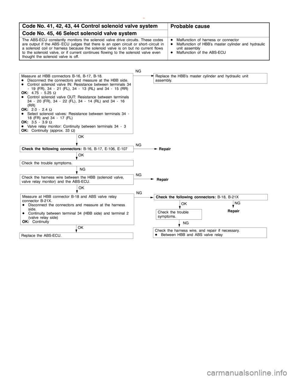
Code No. 41, 42, 43, 44 Control solenoid valve systemProbable cause
Code No. 45, 46 Select solenoid valve system
The ABS-ECU constantly monitors the solenoid valve drive circuits. These codes
are output if the ABS - ECU judges that there is an opencircuit or short - circuit in
a solenoid coil or harness because the solenoid valve is on but no current flows
to the solenoid valve, or if current continues flowing to the solenoid valve even
thought the solenoid valve is off.DMalfunction of harness or connector
DMalfunction of HBB’s master cylinder and hydraulic
unit assembly
DMalfunction of the ABS-ECU
NG
NG
OK
Repair
NG
Replace the HBB’s master cylinder and hydraulic unit
assembly.
OK
Check the following connectors:B-18, B-21X
Check the harness wire, and repair if necessary.
DBetween HBB and ABS valve relay
OK
Check the trouble
symptoms.
NG
Repair
OK
OK
Replace the ABS-ECU.
Repair
Measure at HBB connectors B-16, B-17, B-18.
DDisconnect the connectors and measure at the HBB side.
DControl solenoid valve IN: Resistance between terminals 34
- 19 (FR), 34 - 21 (FL), 34 - 13 (RL) and 34 - 15 (RR)
OK:4.75 - 5.25
W
DControl solenoid valve OUT: Resistance between terminals
34 - 20 (FR), 34 - 22 (FL), 34 - 14 (RL) and 34 - 16
(RR)
OK:2.0 - 2.4
W
DSelect solenoid valves: Resistance between terminals 34 -
18 (FR) and 34 - 17 (FL)
OK:3.5 - 3.9
W
DValve relay monitor: Continuity between terminals 34 - 3
OK:Continuity (approx. 33
W)
NG
Check the following connectors:B-16, B-17, E-106, E-107
Check the trouble symptoms.
NG
Check the harness wire between the HBB (solenoid valve,
valve relay monitor) and the ABS-ECU.
Measure at HBB connector B-18 and ABS valve relay
connector B-21X.
DDisconnect the connectors and measure at the harness
side.
DContinuity between terminal 34 (HBB side) and terminal 2
(valve relay side)
OK:ContinuityNG
www.WorkshopManuals.co.uk
Purchased from www.WorkshopManuals.co.uk
Page 1279 of 1839
ABS <4WD> -Troubleshooting35B-16
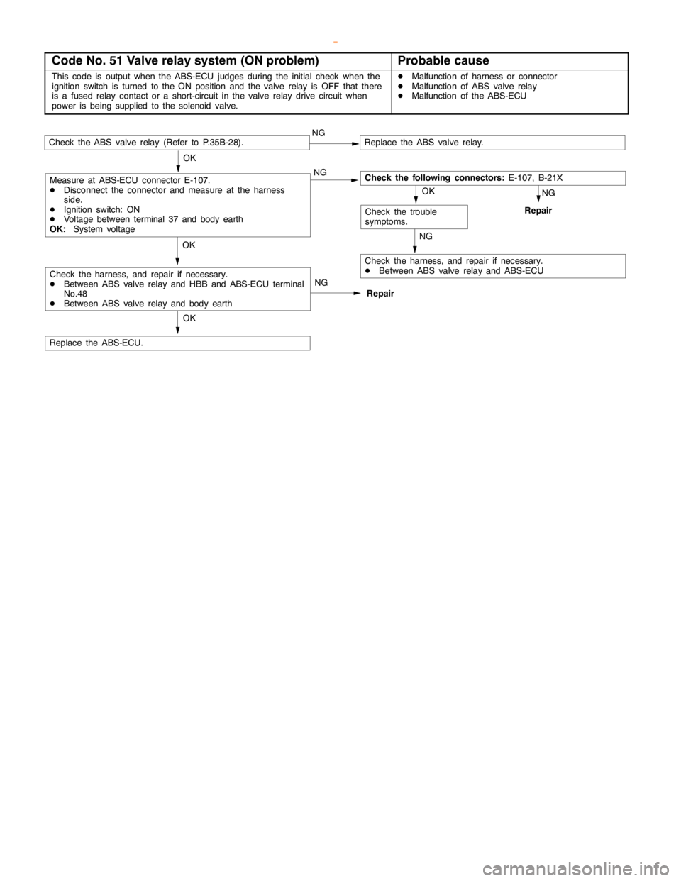
Code No. 51 Valve relay system (ON problem)Probable cause
This code is output when the ABS-ECU judges during the initial check when the
ignition switch is turned to the ON position and the valve relay is OFF that there
is a fused relay contact or a short-circuit in the valve relay drive circuit when
power isbeing supplied to the solenoidvalve.DMalfunction of harness or connector
DMalfunction of ABS valve relay
DMalfunction of the ABS-ECU
Repair NG
Check the ABS valve relay (Refer to P.35B-28).NGReplace the ABS valve relay.
OK
Check the harness, and repair if necessary.
DBetween ABS valve relay and ABS-ECU
OKNG
Repair
OK
Replace the ABS-ECU.
Check the trouble
symptoms.
Check the following connectors:E-107, B-21X OK
NG
NG
Check the harness, and repair if necessary.
DBetween ABS valve relay and HBB and ABS-ECU terminal
No.48
DBetween ABS valve relay and body earth
Measure at ABS-ECU connector E-107.
DDisconnect the connector and measure at the harness
side.
DIgnition switch: ON
DVoltage between terminal 37 and body earth
OK:System voltage
www.WorkshopManuals.co.uk
Purchased from www.WorkshopManuals.co.uk
Page 1280 of 1839
ABS <4WD> -Troubleshooting35B-17
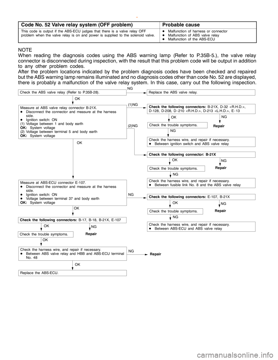
Code No. 52 Valve relay system (OFF problem)Probable cause
This code is output if the ABS-ECU judges that there is a valve relay OFF
problem when the valve relay is on and power is supplied to the solenoid valve.DMalfunction of harness or connector
DMalfunction of ABS valve relay
DMalfunction of the ABS-ECU
NOTE
When reading the diagnosis codes using the ABS warning lamp (Refer to P.35B-5.), the valve relay
connector is disconnected during inspection, with the result that this problem code will be output in addition
to any other problem codes.
After the problem locations indicated by the problem diagnosis codes have been checked and repaired
but the ABS warning lamp remains illuminated and no diagnosis codes other than code No. 52 are displayed,
there is probably a malfunction of the valve relay system. In this case, carry out the following inspection.
NG
Repair (1)NG
Check the ABS valve relay (Refer to P.35B-28).NGReplace the ABS valve relay.
OK
Check the harness wire, and repair if necessary.
DBetween ignition switch and ABS valve relay
OK
Repair
OK
Replace the ABS-ECU.
Check the trouble symptoms.
Check the following connectors:B-21X, D-32
D-128, D-208, D - 210
NG
NG
Check the harness wire, and repair if necessary.
DBetween ABS valve relay and HBB and ABS-ECU terminal
No. 48
(2)NG
Measure at ABS valve relay connector B-21X.
DDisconnect the connector and measure at the harness
side.
DIgnition switch: ON
(1) Voltage between 1 and body earth
OK:System voltage
(2) Voltage between terminal 5 and body earth
OK:System voltage
Check the harness wire, and repair if necessary.
DBetween fusible link No. 8 and the ABS valve relay
OK
NG
Repair
NGCheck the trouble symptoms.
Check the following connector: B-21X
OK
NG
Measure at ABS-ECU connector E-107.
DDisconnect the connector and measure at the harness
side.
DIgnition switch: ON
DVoltage between terminal 37 and body earth
OK:System voltage
OK
NG
Repair
Check the harness wire, and repair if necessary.
DBetween ABS-ECU and ABS valve relayNG
Check the trouble symptoms.
Check the following connectors:E-107, B-21X
OK
OK
NG
RepairCheck the trouble symptoms.
Check the following connectors:B-17, B-18, B-21X, E-107
www.WorkshopManuals.co.uk
Purchased from www.WorkshopManuals.co.uk
Page 1281 of 1839
ABS <4WD> -Troubleshooting35B-18
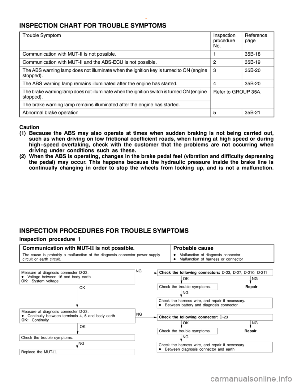
INSPECTION CHART FOR TROUBLE SYMPTOMS
Trouble SymptomInspection
procedure
No.Reference
page
Communication with MUT-II is not possible.135B-18
Communication with MUT-II and the ABS-ECU is not possible.235B-19
The ABS warning lamp does not illuminate when the ignition key is turned to ON (engine
stopped).335B-20
The ABS warning lamp remains illuminated after the engine has started.435B-20
The brake warning lamp does not illuminate when the ignition switch is turned ON (engine
stopped).Refer to GROUP 35A.
The brake warning lamp remains illuminated after the engine has started.
Abnormal brake operation535B-21
Caution
(1) Because the ABS may also operate at times when sudden braking is not being carried out,
such as when driving on low frictional coefficient roads, when turning at high speed or during
high - speed overtaking, check with the customer that the problems are not occurring when
driving under conditions such as these.
(2) When the ABS is operating, changes in the brake pedal feel (vibration and difficulty depressing
the pedal) may occur. This happens because the hydraulic pressure inside the brake line is
continually changing in order to stop the wheels from locking up, and is not a malfunction.
INSPECTION PROCEDURES FOR TROUBLE SYMPTOMS
Inspection procedure 1
Communication with MUT-II
is not possible.
Probable cause
The cause is probably a malfunction of the diagnosis connector power supply
circuit or earth circuit.DMalfunction of diagnosis connector
DMalfunction of harness or connector
NGCheck the following connectors:D-23, D-27, D-210, D-211
NG
Repair
OK
Check the trouble symptoms.
NG
Check the harness wire, and repair if necessary.
DBetween battery and diagnosis connector
OK
NG
NG
Repair
OK
Check the trouble symptoms.
NG
Check the harness wire, and repair if necessary.
DBetween diagnosis connector and earth
OK
NG
Replace the MUT-
II.
Measure at diagnosis connecter D-23.
DVoltage between 16 and body earth
OK:System voltage
Check the following connector:D-23
Measure at diagnosis connecter D-23.
DContinuity between terminals 4, 5 and body earth
OK:Continuity
Check the trouble symptoms.
www.WorkshopManuals.co.uk
Purchased from www.WorkshopManuals.co.uk
Page 1282 of 1839
ABS <4WD> -Troubleshooting35B-19
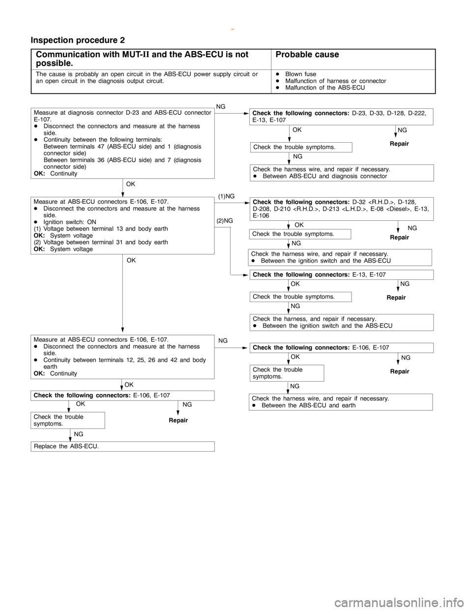
Inspection procedure 2
Communication with MUT-II
and the ABS-ECU is not
possible.
Probable cause
The cause is probably anopencircuit in the ABS-ECU power supply circuit or
an opencircuit in the diagnosis output circuit.DBlown fuse
DMalfunction of harness or connector
DMalfunction of the ABS-ECU
(1)NG
OK
Check the following connectors:E-13, E-107
NG
Repair
OK
Check the trouble symptoms.
NG
Check the harness wire, and repair if necessary.
DBetween ABS-ECU and diagnosis connector
OK
Check the following connectors:D-32
D-208, D-210
E-106
NG
Repair OKCheck the trouble symptoms.
NG
Check the harness wire, and repair if necessary.
DBetween the ignition switch and the ABS-ECU
NG
Repair
OK
Check the trouble symptoms.
NG
Check the harness, and repair if necessary.
DBetween the ignition switch and the ABS-ECU
OK
NG
Repair
OK
NG
Replace the ABS-ECU.
Measure at diagnosis connector D-23 and ABS-ECU connector
E-107.
DDisconnect the connectors and measure at the harness
side.
DContinuity between the following terminals:
Between terminals 47 (ABS-ECU side) and 1 (diagnosis
connector side)
Between terminals 36 (ABS-ECU side) and 7 (diagnosis
connector side)
OK:ContinuityNGCheck the following connectors:D-23, D-33, D-128, D-222,
E-13, E-107
Check the trouble
symptoms.
Check the following connectors:E-106, E-107(2)NG
Measure at ABS-ECU connectors E-106, E-107.
DDisconnect the connectors and measure at the harness
side.
DIgnition switch: ON
(1) Voltage between terminal 13 and body earth
OK:System voltage
(2) Voltage between terminal 31 and body earth
OK:System voltage
OK
Check the following connectors:E-106, E-107
Repair
OK
Check the trouble
symptoms.
NG
Check the harness wire, and repair if necessary.
DBetween the ABS-ECU and earthNG NG
Measure at ABS-ECU connectors E-106, E-107.
DDisconnect the connectors and measure at the harness
side.
DContinuity between terminals 12, 25, 26 and 42 and body
earth
OK:Continuity
www.WorkshopManuals.co.uk
Purchased from www.WorkshopManuals.co.uk
Page 1283 of 1839
ABS <4WD> -Troubleshooting35B-20
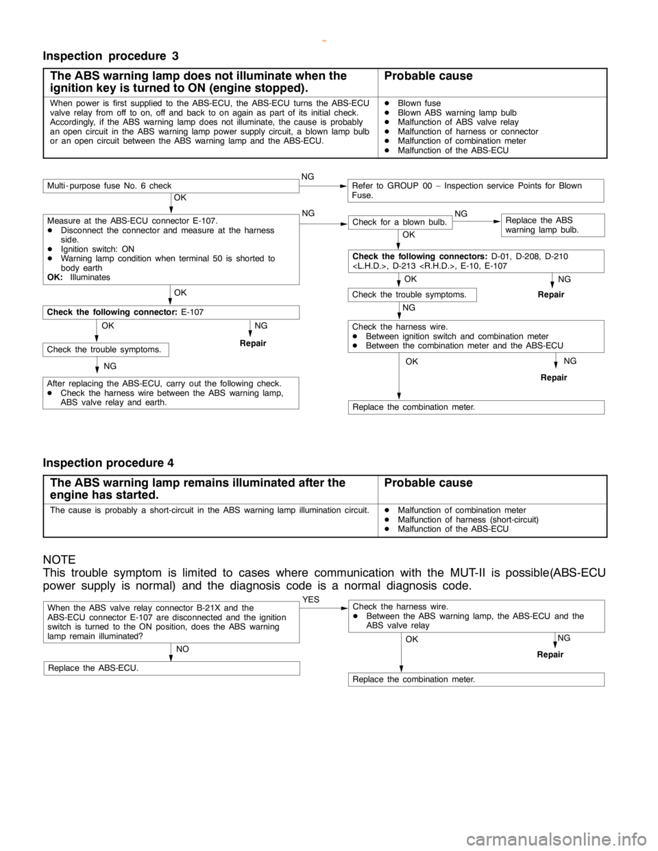
Inspection procedure 3
The ABS warning lamp does not illuminate when the
ignition key is turned to ON (engine stopped).
Probable cause
When power is first supplied to the ABS-ECU, the ABS-ECU turns the ABS-ECU
valve relay from off to on, off and back to onagain aspart of its initial check.
Accordingly, if the ABS warninglampdoes not illuminate, the cause is probably
an opencircuit in the ABS warninglamppower supply circuit, a blownlamp bulb
or an opencircuit between the ABS warninglamp and theABS-ECU.DBlown fuse
DBlown ABS warninglamp bulb
DMalfunction of ABS valve relay
DMalfunction of harness or connector
DMalfunction of combination meter
DMalfunction of the ABS-ECU
NG
Replace the combination meter.
NG
Repair
OK
NG
Check for a blown bulb.Replace the ABS
warning lamp bulb.
OK
NG
Repair
OK
Check the trouble symptoms.
Multi - purpose fuse No. 6 checkNGRefer to GROUP 00 – Inspection service Points for Blown
Fuse.
NG
Check the harness wire.
DBetween ignition switch and combination meter
DBetween the combination meter and the ABS-ECU
OK
OK
After replacing the ABS-ECU, carry out the following check.
DCheck the harness wire between the ABS warning lamp,
ABS valve relay and earth.
Check the following connector:E-107
NG
RepairCheck the trouble symptoms.OK
NG
Check the following connectors:D-01, D-208, D-210
Measure at the ABS-ECU connector E-107.
DDisconnect the connector and measure at the harness
side.
DIgnition switch: ON
DWarning lamp conditionwhen terminal 50 is shorted to
body earth
OK:Illuminates
Inspection procedure 4
The ABS warning lamp remains illuminated after the
engine has started.
Probable cause
The cause is probably a short-circuit in the ABS warninglamp illuminationcircuit.DMalfunction of combination meter
DMalfunction of harness (short-circuit)
DMalfunction of the ABS-ECU
NOTE
This trouble symptom is limited to cases where communication with the MUT-II is possible(ABS-ECU
power supply is normal) and the diagnosis code is a normal diagnosis code.
When the ABS valve relay connector B-21X and the
ABS-ECU connector E-107 are disconnected and the ignition
switch is turned to the ON position, does the ABS warning
lamp remain illuminated?YES
NO
Replace the ABS-ECU.
Replace the combination meter.
NG
Repair
OK
Check the harness wire.
DBetween the ABS warning lamp, the ABS-ECU and the
ABS valve relay
www.WorkshopManuals.co.uk
Purchased from www.WorkshopManuals.co.uk
Page 1284 of 1839
ABS <4WD> -Troubleshooting35B-21
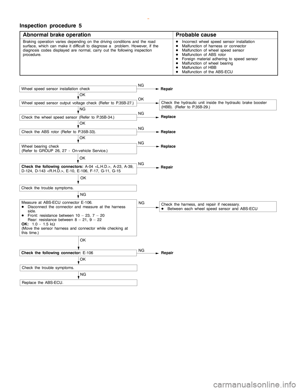
Inspection procedure 5
Abnormal brake operation
Probable cause
Braking operation variesdepending on the driving conditions and the road
surface, which can make it difficult to diagnose a problem. However, if the
diagnosis codes displayed are normal, carry out the following inspection
procedure.DIncorrect wheel speed sensor installation
DMalfunction of harness or connector
DMalfunction of wheel speed sensor
DMalfunction of ABS rotor
DForeign material adhering to speed sensor
DMalfunction of wheel bearing
DMalfunction of HBB
DMalfunction of the ABS-ECU
Wheel speed sensor installation checkNG
Repair
OKCheck the hydraulic unit inside the hydraulic brake booster
(HBB). (Refer to P.35B-29.)
NG
Check the wheel speed sensor (Refer to P.35B-34.)NG
OK
Check the ABS rotor (Refer to P.35B-33).NG
Replace
OK
NG
Replace
OK
NG
Repair
OK
NG
NG
OK
Check the following connector:E-106
OK
Check the trouble symptoms.
NG
Replace the ABS-ECU.NG
Repair
Check the harness, and repair if necessary.
DBetween each wheel speed sensor and ABS-ECU ReplaceMeasure at ABS-ECU connector E-106.
DDisconnect the connector and measure at the harness
side.
DFront: resistance between 10 – 23, 7 – 20
Rear: resistance between 8 – 21, 9 – 22
OK:1.0 - 1.5 k
W
(Move the sensor harness and connector while checking at
this time.)
Check the following connectors:A-04
D-124, D-143
Wheel bearing check
(Refer to GROUP 26, 27 - On-vehicle Service.)
Check the trouble symptoms.
Wheel speed sensor output voltage check (Refer to P.35B-27.)OK
www.WorkshopManuals.co.uk
Purchased from www.WorkshopManuals.co.uk