2000 MITSUBISHI MONTERO ECU
[x] Cancel search: ECUPage 1596 of 1839
CHASSIS ELECTRICAL-Combination Meter54A-26
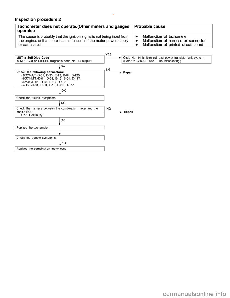
Inspection procedure 2
Tachometer does not operate.(Other meters and gauges
operate.)
Probable cause
The cause is probably that the ignition signal is not being input from
the engine, or that there is a malfunction of the meter power supply
or earth circuit.D
Malfunction of tachometer
D
Malfunction of harness or connector
D
Malfunction of printed circuit board
OK
NG
Replace the combination meter case.
OK
Check the trouble symptoms.
NO
MUT-
IISelf-Diag Code
Is MPI, GDI or DIESEL diagnosis code No. 44 output?YESCode No. 44 Ignition coil and power transistor unit system
(Refer to GROUP 13A - Troubleshooting.)
NG
Replace the tachometer.
NG
NG
Repair RepairCheck the harness between the combination meter and the
engine-ECU.
OK:Continuity
Check the trouble symptoms.
Check the following connectors:
<6G74-A/T>D-01, D-33, E-13, B-04, D-120,
<6G74-M/T>D-01, D-33, E-13, B-04, D-117,
<4M41>D-01, D-33, E-13, D-112,
<4D56>D-01, D-33, E-13, B-07, B-07-1
www.WorkshopManuals.co.uk
Purchased from www.WorkshopManuals.co.uk
Page 1599 of 1839
CHASSIS ELECTRICAL-Combination Meter54A-29
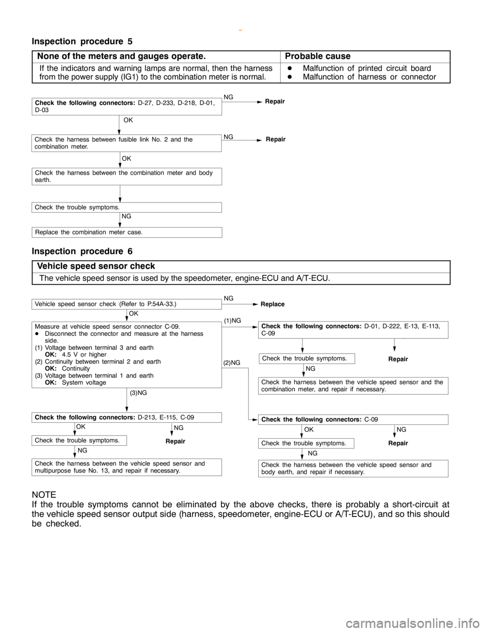
Inspection procedure 5
None of the meters and gauges operate.
Probable cause
If the indicators and warning lamps are normal, then the harness
from the power supply (IG1) to the combination meter is normal.D
Malfunction of printed circuit board
D
Malfunction of harness or connector
NGRepair NG
OK
Check the trouble symptoms.Repair
OK
Check the harness between the combination meter and body
earth.
Check the following connectors:D-27, D-233, D-218, D-01,
D-03
NG
Check the harness between fusible link No. 2 and the
combination meter.
Replace the combination meter case.
Inspection procedure 6
Vehicle speed sensor check
The vehicle speed sensor is used by the speedometer, engine-ECU and A/T-ECU.
NG
Check the harness between the vehicle speed sensor and
body earth, and repair if necessary.
RepairNG
OK
Check the trouble symptoms.NG
Check the harness between the vehicle speed sensor and
multipurpose fuse No. 13, and repair if necessary.
RepairNG
OK
Check the trouble symptoms.
Check the following connectors:D-213, E-115, C-09
(3)NG
(2)NG
Check the following connectors:C-09
NG
Check the harness between the vehicle speed sensor and the
combination meter, and repair if necessary.
RepairNG
OK
Check the trouble symptoms.
OK
Measure at vehicle speed sensor connector C-09.
DDisconnect the connector and measure at the harness
side.
(1) Voltage between terminal 3 and earth
OK:4.5 V or higher
(2) Continuity between terminal 2 and earth
OK:Continuity
(3) Voltage between terminal 1 and earth
OK:System voltage(1)NGCheck the following connectors:D-01, D-222, E-13, E-113,
C-09
Vehicle speed sensor check (Refer to P.54A-33.)NG
Replace
NOTE
If the trouble symptoms cannot be eliminated by the above checks, there is probably a short-circuit at
the vehicle speed sensor output side (harness, speedometer, engine-ECU or A/T-ECU), and so this should
be checked.
www.WorkshopManuals.co.uk
Purchased from www.WorkshopManuals.co.uk
Page 1624 of 1839

CHASSIS ELECTRICAL -Clock or Center Display54A-54
BEFORE REMOVING THE BATTERY
The Center display has a large amount of data unique to the vehicle in its memory. When the battery
cable is disconnected, that memory is affected as shown in the table below. Accordingly, it is necessary
to make sure that you take notes of important information before disconnecting the battery cable.
FunctionInput function/memoryWhen battery cable is disconnected
Clock set on displayCurrent timeRetains data for approx. 1 hour
Vehicle model setShort (3-door models)/long (5-door
models)Retains data for approx. 1 hour
Brightness set for displayPosition set on displayRetains data for approx. 1 hour
Unit set for trip computerkm or mile, L/100km or mpg or km/L
Average vehicle speed after resetRetains data for approx. 1 hour
Average vehicle speed on displayAverage vehicle speed after resetRetains data for approx. 1 hour
Average fuel consumption on displayAverage fuel consumption after resetRetains data for approx. 1 hour
Cruising range on displayCruising range, fuel economyRetains data for approx. 1 hour
Outside temperature on displayOutside temperature after the ignition
switch is turned to the OFF(LOCK)
position.Retains data for approx. 1 hour
* The outside temperature sensor
is located near the engine.
Therefore, incorrectly high
temperature may be displayed
when the battery cable is
reconnected within one hour.
DIAGNOSIS FUNCTION FOR CENTER DISPLAY
Center display has the following diagnosis function:
FunctionContents
Service functionThere are the following 4 diagnosis modes available
1. Check of vehicle informationThe vehicle, short (3-door models)/long (5-door models) set
2. Check of LCD segmentsThe LCD segments for display available to light on or not
3. Check of sensorsOutside temperature, voltage of fuel gauge unit, system voltage, fuel amount
remains, fuel economy calculated after supply of fuel
4. Check of units connected into
the center displayThe units connected on display
Voltage (%) on terminal for MUT-II
Vehicle speed signal sent by engine-ECU
Oscillating signal
www.WorkshopManuals.co.uk
Purchased from www.WorkshopManuals.co.uk
Page 1630 of 1839

CHASSIS ELECTRICAL -Clock or Center Display54A-60
Terminal
No.Input/
OutputSignal symbolTerminal
voltage (V)Wiring harness
problemTrouble symptom caused by wiring
harness problem
Open
circuitShort
circuit
15Input/
OutputKHi: System
voltage
Lo: 0-1ExistsExistsValues on trip information screen (average
vehicle speed, fuel consumption and
cruising distance) are abnormal. Commu-
nication is impossible between the
engine-ECU and the MUT-II.
16------
17Input/
OutputM-BUSY
(AUDIO)Hi: 4-5
Lo: 0-1ExistsExistsAudio display does not appear. Panel
switch cannot be operated for audio unit.
Nighttime illumination does not appear for
audio unit.
18-SHIELD-GND----
19Input/
OutputM-BUSY
(A/C)Hi: 4-5
Lo: 0-1ExistsExistsA/C display does not appear.
Outside air temperature does not appear
20-SHIELD-GND----
21, 22------
23InputEX-TEMPExistsExistsOutside air temperature does not appear.
24InputILL+Hi: System
voltageExists-Nighttime illumination does not appear for
audio units.
Lo: 0-1
-ExistsBlown multipurpose fuse.
25InputACC (ACCSystem volt-Exists-Screen display does not appear.
power supply)age
-ExistsBlown multipurpose fuse.
26Input+BSystem volt-Exists-Screen display does not appear.
age
-ExistsBlown multipurpose fuse.
27InputVSSHi: System
voltage
Lo: 0-1ExistsExistsAbnormal outside air temperature ap-
pears.
(only diesel-powered vehicles)
28-GND (earth)-Exists-Screen display does not appear.
29, 30------
31-GND-TEMPExistsExistsOutside air temperature does not appear.
32InputILL -ExistsExistsThe display screen can not be dimmed.
33InputFUEL GAUGE-ExistsAbnormal cruising distance appears.
34, 35------
36InputIG1Hi: System
voltageExists-Communication with engine-ECU is im-
possible. Abnormal driving data values
appear.
-ExistsCommunication with engine-ECU is im-
possible. Abnormal driving data values
appear. Blown multipurpose fuse.
www.WorkshopManuals.co.uk
Purchased from www.WorkshopManuals.co.uk
Page 1633 of 1839
CHASSIS ELECTRICAL -Clock or Center Display54A-63
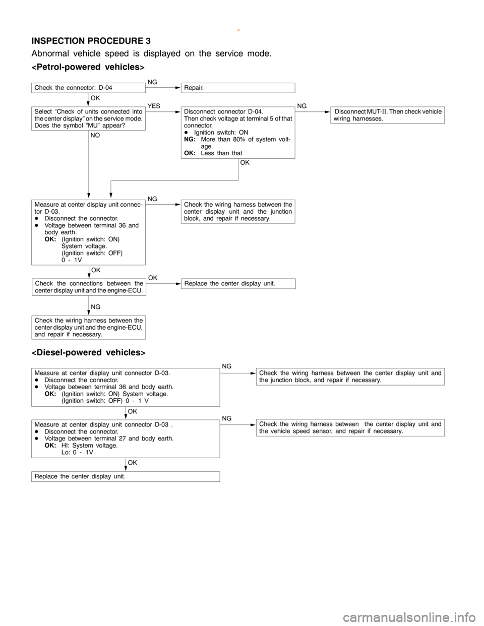
INSPECTION PROCEDURE 3
Abnormal vehicle speed is displayed on the service mode.
OK
NGRepair.
Measure at center display unit connec-
tor D-03.
DDisconnect the connector.
DVoltage between terminal 36 and
body earth.
OK:(Ignition switch: ON)
System voltage.
(Ignition switch: OFF)
0-1VNGCheck the wiring harness between the
center display unit and the junction
block, and repair if necessary.
NG
Check the wiring harness between the
center display unit and the engine-ECU,
and repair if necessary.
Select “Check of units connected into
the center display” on the service mode.
Does the symbol “MU” appear?YES NGDisconnect MUT-
II. Then check vehicle
wiring harnesses.Disconnect connector D-04.
Then check voltage at terminal 5 of that
connector.
DIgnition switch: ON
NG:More than 80% of system volt-
age
OK:Less than that
OK NO
OK
Check the connections between the
center display unit and the engine-ECU.OKReplace the center display unit.
Check the connector: D-04
Measure at center display unit connector D-03.
DDisconnect the connector.
DVoltage between terminal 36 and body earth.
OK:(Ignition switch: ON) System voltage.
(Ignition switch: OFF) 0 - 1 VNGCheck the wiring harness between the center display unit and
the junction block, and repair if necessary.
OK
Measure at center display unit connector D-03 .
DDisconnect the connector.
DVoltage between terminal 27 and body earth.
OK:HI: System voltage.
Lo: 0 - 1VNGCheck the wiring harness between the center display unit and
the vehicle speed sensor, and repair if necessary.
OK
Replace the center display unit.
www.WorkshopManuals.co.uk
Purchased from www.WorkshopManuals.co.uk
Page 1636 of 1839
CHASSIS ELECTRICAL -Clock or Center Display54A-66
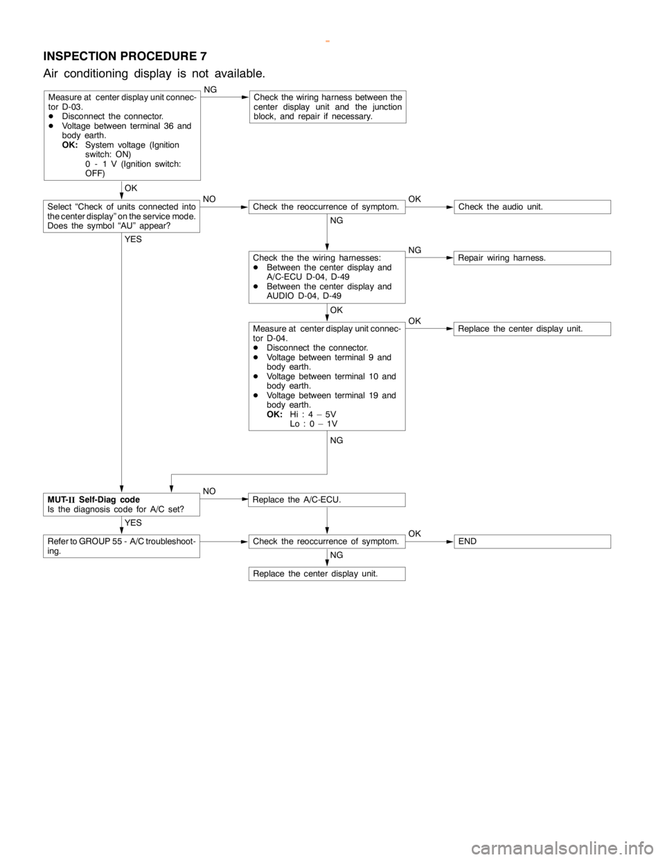
INSPECTION PROCEDURE 7
Air conditioning display is not available.
Measure at center display unit connec-
tor D-03.
DDisconnect the connector.
DVoltage between terminal 36 and
body earth.
OK:System voltage (Ignition
switch: ON)
0 - 1 V (Ignition switch:
OFF)NGCheck the wiring harness between the
center display unit and the junction
block, and repair if necessary.
OK
NO OK
Check theaudio unit.
NG
NG
Repair wiring harness.
OK
OK
Replace the center display unit.
YES
Replace the A/C-ECU.
YES
Refer to GROUP 55 - A/C troubleshoot-
ing.Check the reoccurrence of symptom.OKEND
NG
Replace the center display unit.
Measure at center display unit connec-
tor D-04.
DDisconnect the connector.
DVoltage between terminal 9 and
body earth.
DVoltage between terminal 10 and
body earth.
DVoltage between terminal 19 and
body earth.
OK:Hi:4–5V
Lo:0–1V
Check the the wiring harnesses:
DBetween the center display and
A/C-ECU D-04, D-49
DBetween the center display and
AUDIO D-04, D-49
Check the reoccurrence of symptom.Select “Check of units connected into
the center display” on the service mode.
Does the symbol “AU” appear?
MUT-
IISelf-Diag code
Is the diagnosis code for A/C set?NG
NO
www.WorkshopManuals.co.uk
Purchased from www.WorkshopManuals.co.uk
Page 1641 of 1839
CHASSIS ELECTRICAL -Radio/Tape Player54A-71
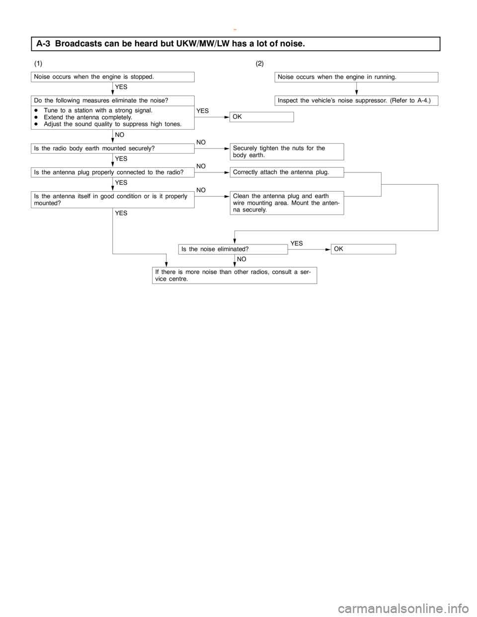
A-3 Broadcasts can be heard but UKW/MW/LW has a lot of noise.
(1)(2)
Noise occurs when theengine is stopped.
YES
Do the following measures eliminate the noise?
DTune to a station with a strong signal.
DExtend the antenna completely.
DAdjust the sound quality to suppresshightones.YES
OK
NO
Is the radio body earth mounted securely?NOSecurely tighten the nuts for the
body earth.
YES
Is the antenna plug properly connected to the radio?NOCorrectly attach the antenna plug.
YES
Is the antenna itself ingood condition or is it properly
mounted?NOClean the antenna plug and earth
wire mounting area. Mount the anten-
na securely.
YES
If there is more noise than other radios, consult a ser-
vice centre.
Is the noise eliminated?
NOYES
OK
Noise occurs when theengine in running.
Inspect the vehicle’s noise suppressor. (Refer to A-4.)
www.WorkshopManuals.co.uk
Purchased from www.WorkshopManuals.co.uk
Page 1644 of 1839
CHASSIS ELECTRICAL -Radio/Tape Player54A-74
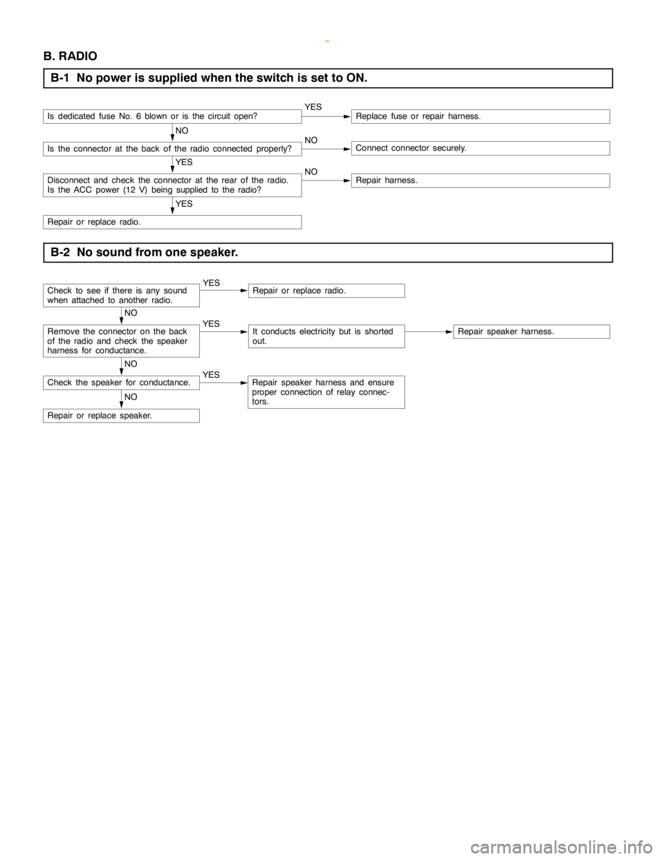
B. RADIO
B-1 No power is supplied when the switch is set to ON.
Is dedicated fuse No. 6 blown or is the circuitopen?YESReplace fuse or repair harness.
NO
Is the connector at the back of the radio connected properly?NOConnect connector securely.
YES
Disconnect and check the connector at the rear of the radio.
Is the ACC power (12 V)being supplied to the radio?NORepair harness.
YES
Repair or replace radio.
B-2 No sound from one speaker.
Check to see if there is any sound
when attached to another radio.YESRepair or replace radio.
NO
Remove the connector on the back
of the radio and check the speaker
harness for conductance.YESIt conducts electricity but is shorted
out.Repair speaker harness.
NO
Check the speaker for conductance.YESRepair speaker harness and ensure
proper connection of relay connec-
tors.
NO
Repair or replace speaker.
www.WorkshopManuals.co.uk
Purchased from www.WorkshopManuals.co.uk