2000 MITSUBISHI MONTERO ECU
[x] Cancel search: ECUPage 1510 of 1839

SRS -Troubleshooting52B-10
Code No.21, 22, 61, 62 Driver’s side air bag module (squib)
systemProbable cause
These diagnosis codes are output if there is an abnormal resistance between the
input terminals of the driver’s side air bagmodule(squib) inside the SRS-ECU.
The trouble causes for each diagnosis code No. are as follow.
However, as for code Nos.21 and 22, if the vehicle’s condition return to normal,
SRS warning lampwill go out. (Diagnosis code will remain stored)DMalfunction of clock spring
DPartially open asclock spring is not in neutral
position
DMalfunction of harness or connector
DMalfunction of driver’s air bagmodule(squib)
DMalfunction of SRS-ECU
Table 3
Code No.Trouble Symptom
21D
Short circuit in driver’s air bag module (squib) or harness short
D
Short circuit in clock spring
D
Poor connector contact*
22D
Open circuit in driver’s air bag module (squib) or open harness
D
Open circuit in clock spring
D
Disconnected driver’s air bag module (squib) connector
D
Partially open as clock spring is not in neutral position
D
Poor connector contact
61Short circuit in driver’s air bag module (squib) harness leading to the power supply
62Short circuit in driver’s air bag module (squib) harness leading to the earth
NOTE
*: The shorting bars, which short positive (+) and negative ( - ) wires to prevent the air bags from accidental
deployment during the disconnection of the connector, are set in the squib circuit connectors. In
a defective connector, the short-bar may be still working even after the connection of the connecter.
www.WorkshopManuals.co.uk
Purchased from www.WorkshopManuals.co.uk
Page 1513 of 1839

SRS -Troubleshooting52B-13
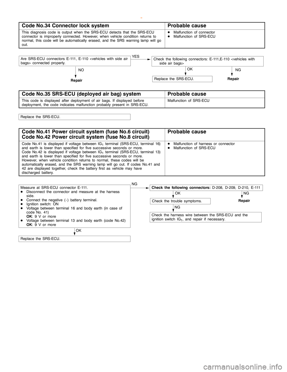
Code No.34 Connector lock systemProbable cause
This diagnosis code is output when the SRS-ECU detects that the SRS-ECU
connector is improperly connected. However, when vehicle condition returns to
normal, this code will be automatically erased, and the SRS warninglampwill go
out.DMalfunction of connector
DMalfunction of SRS-ECU
NG YES
Are SRS-ECU connectors E-111, E-110
Repair
Replace the SRS-ECU.
RepairNOOK
Code No.35 SRS-ECU (deployed air bag) systemProbable cause
This code is displayed after deployment of air bags. If displayed before
deployment, the code indicates malfunction probably present in SRS-ECU.Malfunction of SRS-ECU
Replace the SRS-ECU.
Code No.41 Power circuit system (fuse No.6 circuit)
Code No.42 Power circuit system (fuse No.8 circuit)Probable cause
Code No.41 is displayed if voltage between IG1terminal (SRS-ECU, terminal 16)
and earth is lower than specified for fivesuccessive seconds ormore.
Code No.42 is displayed if voltage between IG
1terminal (SRS-ECU, terminal 13)
and earth is lower than specified for fivesuccessive seconds ormore.
However, when vehicle condition returns to normal, these codes will be
automatically erased, and the SRS warning lampwill go out. If codes No.41 and
42 are displayed together, check the battery first as vehicle may have
discharged battery.
DMalfunction of harness or connector
DMalfunction of SRS-ECU
NGOK
NG NG
OK
Replace the SRS-ECU.
Measure at SRS-ECU connector E-111.
DDisconnect the connector and measure at the harness
side.
DConnect the negative ( - ) battery terminal.
DIgnition switch: ON
DVoltage between terminal 16 and body earth (in case of
code No. 41)
OK: 9 V or more
DVoltage between terminal 13 and body earth (code No.42)
OK: 9 V or moreCheck the following connectors:D-208, D-209, D-210, E-111
Check the trouble symptoms.Repair
Check the harness wire between the SRS-ECU and the
ignition switch IG
1, and repair if necessary.
www.WorkshopManuals.co.uk
Purchased from www.WorkshopManuals.co.uk
Page 1514 of 1839

SRS -Troubleshooting52B-14
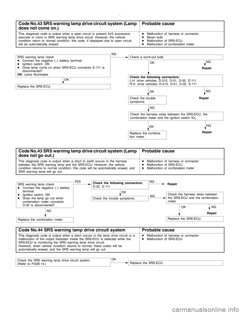
Code No.43 SRS warning lamp drive circuit system (Lamp
does not come on.)Probable cause
This diagnosis code is output when aopencircuit is present for5 successive
seconds or more in SRS warninglampdrive circuit. However, the vehicle
condition return to normal condition, this code, if displayed due toopencircuit,
will be automatically erased.DMalfunction of harness or connector
DBlownbulb
DMalfunction of SRS-ECU
DMalfunction of combination meter
NGOK
NG
NGOK
Check the trouble
symptoms.
NG
Repair
Check the harness wires between the SRS-ECU, the
combination meter and the ignition switch IG
1.
OK
Replace the SRS-ECU.
Repair
Repair
OK
Check the following connectors:
L.H. drive vehicles: D-210, D-01, D-02, E-111
R.H. drive vehicles: D-213, D-01, D-02, E-111
SRS warning lampcheck
DConnect the negative ( - ) battery terminal.
DIgnition switch: ON
DDoeslampcome on when SRS-ECU connector E-111 is
disconnected?
OK: Lamp illuminatesNGCheck a burnt-out bulb.
Replace the combina-
tion meter.
Code No.43 SRS warning lamp drive circuit system (Lamp
does not go out.)Probable cause
This diagnosis code is output when a short to earth occurs in the harness
between the SRS warning lamp and theSRS-ECU. However, the vehicle
condition returns to normal condition, this code will be automatically erased, and
SRS warning lampwill go out.DMalfunction of harness or connector
DMalfunction of SRS-ECU
DMalfunction of combination meter
OKNG
NG
RepairNG
NO
Replace the combination meter.
SRS warning lampcheck
DConnect the negative ( - ) battery
terminal.
DIgnition switch: ON
DDoes thelamp go outwhen
combination meter connector
D-02 is disconnected?YESCheck the following connectors:
D-02, E-111Repair
Check the trouble symptoms.
OK
Replace the SRS-ECU.
Check the harness wires between
the SRS-ECU and the combination
meter.
Code No.44 SRS warning lamp drive circuit systemProbable cause
This diagnosis code is output when a short occurs in thelampdrive circuit or a
malfunction of the output transistor inside the SRS-ECU is detected while the
SRS-ECU is monitoring the SRS warninglampdrive circuit.
However, when vehicle condition returns to normal, these codes will be
automatically erased, and the SRS warning lampwill go out.DMalfunction of harness or connector
DMalfunction of SRS-ECU
Check the SRS warninglampdrive circuit system.
(Refer to P.52B-14.)OKReplace the SRS-ECU.
www.WorkshopManuals.co.uk
Purchased from www.WorkshopManuals.co.uk
Page 1517 of 1839

SRS -Troubleshooting52B-17
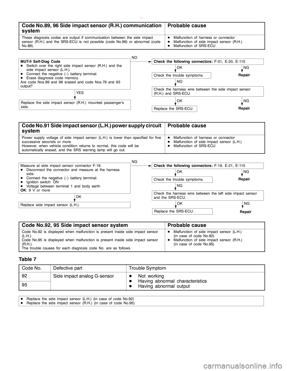
Code No.89, 96 Side impact sensor (R.H.) communication
systemProbable cause
These diagnosis codes are output if communication between the side impact
sensor (R.H.) and the SRS-ECU is not possible (code No.96) or abnormal (code
No.89).DMalfunction of harness or connector
DMalfunction of side impact sensor (R.H.)
DMalfunction of SRS-ECU
OK
Check the trouble symptoms.
NG
Repair
NG
RepairOK
Replace the SRS-ECU.
YES
Replace the side impact sensor (R.H.) mounted passenger’s
side.
MUT-II Self-Diag Code
DSwitch over the right side impact sensor (R.H.) and the
side impact sensor (L.H.).
DConnect the negative ( - ) battery terminal.
DErase diagnosis code memory.
Are code Nos.89 and 96 erased and code Nos.79 and 93
output?NOCheck the following connectors:F-01, E-20, E-110
NG
Check the harness wire between the side impact sensor
(R.H.) and SRS-ECU.
Code No.91 Side impact sensor (L.H.) power supply circuit
systemProbable cause
Power supply voltage of side impact sensor (L.H.) is lower than specified for five
successive seconds ormore.
However, when vehicle condition returns to normal, this code will be
automatically erased, and the SRS warning lampwill go out.DMalfunction of harness or connector
DMalfunction of side impact sensor (L.H.)
DMalfunction of SRS-ECU
Measure at side impact sensor connector F-19.
DDisconnect the connector and measure at the harness
side.
DConnect the negative ( - ) battery terminal.
DIgnition switch: ON
DVoltage between terminal 1 and body earth
OK: 9 V or moreNGCheck the following connectors:F-19, E-21, E-110
OK
Check the trouble symptoms.
NG
Repair
NG
Check the harness wire between the left side impact sensor
and the SRS-ECU.
NG
RepairOK
Replace the SRS-ECU.
OK
Replace side impact sensor (L.H.).
Code No.92, 95 Side impact sensor systemProbable cause
Code No.92 is displayed when malfunction is present inside side impact sensor
(L.H.).
Code No.95 is displayed when malfunction is present inside side impact sensor
(R.H.).
The trouble causes for each diagnosis code No. are as follows.DMalfunction of side impact sensor (L.H.)
(in case of code No.92)
DMalfunction of side impact sensor (R.H.)
(in case of code No.95)
Table 7
Code No.Defective partTrouble Symptom
92Side impact analog G-sensorD
Not working
95D
Having abnormal characteristics
D
Having abnormal output
DReplace the side impact sensor (L.H.) (in case of code No.92)
DReplace the side impact sensor (R.H.) (in case of code No.95)
www.WorkshopManuals.co.uk
Purchased from www.WorkshopManuals.co.uk
Page 1518 of 1839

SRS -Troubleshooting52B-18
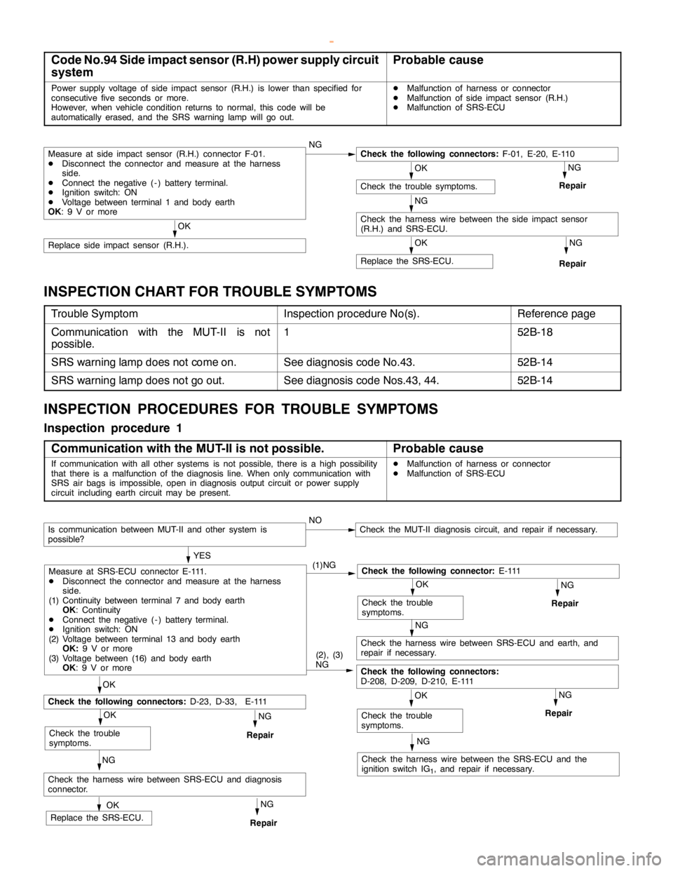
Code No.94 Side impact sensor (R.H) power supply circuit
systemProbable cause
Power supply voltage of side impact sensor (R.H.) is lower than specified for
consecutive five seconds or more.
However, when vehicle condition returns to normal, this code will be
automatically erased, and the SRS warning lampwill go out.DMalfunction of harness or connector
DMalfunction of side impact sensor (R.H.)
DMalfunction of SRS-ECU
Measure at side impact sensor (R.H.) connector F-01.
DDisconnect the connector and measure at the harness
side.
DConnect the negative ( - ) battery terminal.
DIgnition switch: ON
DVoltage between terminal 1 and body earth
OK: 9 V or moreNGCheck the following connectors:F-01, E-20, E-110
OK
Check the trouble symptoms.
NG
Repair
NG
Check the harness wire between the side impact sensor
(R.H.) and SRS-ECU.
NG
RepairOK
Replace the SRS-ECU.
OK
Replace side impact sensor (R.H.).
INSPECTION CHART FOR TROUBLE SYMPTOMS
Trouble SymptomInspection procedure No(s).Reference page
Communication with the MUT-II is not
possible.152B-18
SRS warning lamp does not come on.See diagnosis code No.43.52B-14
SRS warning lamp does not go out.See diagnosis code Nos.43, 44.52B-14
INSPECTION PROCEDURES FOR TROUBLE SYMPTOMS
Inspection procedure 1
Communication with the MUT-II is not possible.
Probable cause
If communication with all other systems is not possible, there is ahigh possibility
that there is a malfunction of the diagnosis line. When only communication with
SRS air bags is impossible,open in diagnosis outputcircuit or power supply
circuit including earth circuit may be present.DMalfunction of harness or connector
DMalfunction of SRS-ECU
NG
NG
NG
Check the harness wire between the SRS-ECU and the
ignition switch IG
1, and repair if necessary.
NOCheck the MUT-II diagnosis circuit, and repair if necessary.
OK
Check the trouble
symptoms.
NG
Repair
NG
Check the harness wire between SRS-ECU and earth, and
repair if necessary.
OK
Check the trouble
symptoms.
NG
RepairOK
OK
Check the trouble
symptoms.
Check the harness wire between SRS-ECU and diagnosis
connector.
OK
Replace the SRS-ECU.
YES
(1)NG
Check the following connector:E - 111
(2), (3)
NG
Check the following connectors:
D-208, D-209, D-210, E-111
Measure at SRS-ECU connector E-111.
DDisconnect the connector and measure at the harness
side.
(1) Continuity between terminal 7 and body earth
OK: Continuity
DConnect the negative ( - ) battery terminal.
DIgnition switch: ON
(2) Voltage between terminal 13 and body earth
OK:9 V or more
(3) Voltage between (16) and body earth
OK: 9 V or more
Repair
NG
Repair
Check the following connectors:D-23, D-33, E-111
Is communication between MUT-II and other system is
possible?
www.WorkshopManuals.co.uk
Purchased from www.WorkshopManuals.co.uk
Page 1523 of 1839

SRS -Post-collision Diagnosis52B-23
POST-COLLISION DIAGNOSIS
Whether or not the air bags have deployed, check and service
the vehicle after collision as follows:
SRS-ECU MEMORY CHECK
1. Connect the MUT-
IIto the diagnosis connector. (Refer
to GROUP 00 – How to Use Troubleshooting/Inspection
Service Points.)
Caution
Refer to that the ignition switch is LOCK(OFF) when
connecting or disconnecting MUT-II
.
2. Read (and write down) all displayed diagnosis codes.
(Refer to P.52B-7.)
NOTE
If battery power supply has been shut down by the
collision, the MUT-
IIcannot communicate with the
SRS-ECU. Check and, repair if necessary, the instrument
panel wiring harness before the next job.
3. Use the the MUT-
IIto read the data list (how long trouble(s)
have continued and how often memory have been
erased).
Data list
NoService Data ItemApplicability
92Number indication how often the memory is cleared.Maximum time to be stored: 250
93How long problem have lasted (How long it takes
from the occurrence of the problem till the first air bag
squib igniting signal)Maximum time to be stored: 9999 minutes
(approximately 7 days)
94How long problem(s) have lasted (How long it takes
from the first air bag squib igniting signal till now.)
4. Erase the diagnosis codes and after waiting 5 seconds
or more read (and write down) all displayed diagnosis
codes. (Refer to P.52B-7.)
REPAIR PROCEDURE
DEPLOYED DRIVER’S AND FRONT PASSENGER’S AIR
BAGS
1. Replace the following parts with new ones.
DSRS-ECU (Refer to P.52B-30.)
DDriver’s air bag module (Refer to P.52B-32.)
DFront passenger’s air bag module (Refer to P.52B-32.)
2. Check the following parts and replace if malfunction is
found:
DClock spring (Refer to P.52B-32.)
DSteering wheel, steering column and intermediate
joint
(1) Check the wiring harness (built into steering
wheel) and connectors for damage, and terminals
for deformation.
(2) Check the driver’s air bag module for proper
installation to the steering wheel.
www.WorkshopManuals.co.uk
Purchased from www.WorkshopManuals.co.uk
Page 1561 of 1839

SRS -Troubleshooting52B-9
Code No.56, 57, 58, 59 System inside SRS-ECUProbable cause
These diagnostic trouble codes are output when a fault is detected in the SRS-ECU.
The defective parts and trouble causes for each diagnosis code No. are as follows.DMalfunction of SRS-ECU
Code No.Defective partsTrouble causes
56Driver’s side pre-tensioner
(squibignitiondrivecircuit)
DShort circuit in the squib ignition drive circuit
57(squibignitiondrive circuit)DOpen circuit in the squib ignition drive circuit
58Front passenger’s side pre-
tensioner(squibignitiondrive
DShort circuit in the squib ignition drive circuit
59
tensioner(squibignitiondrive
circuit)
DOpen circuit in the squib ignition drive circuit
If the diagnosis code(s) above is set, replace the SRS-ECU.
www.WorkshopManuals.co.uk
Purchased from www.WorkshopManuals.co.uk
Page 1562 of 1839

SRS -Post-collision Diagnosis52B-10
POST-COLLISION DIAGNOSIS
Check and service the vehicle after collision as follows
regardless of the operation of the pre-tensioner:
SRS-ECU MEMORY CHECK
The check procedure is the same as before.
REPAIR PROCEDURE
WHEN PRE-TENSIONER OPERATES IN A COLLISION.
1. Replace the following parts with new ones.
DSRS-ECU
DFront impact sensor
DSeat belt with pre-tensioner (Refer to P.52B-12.)
2. Check harnesses for binding, connectors for damage,
poor connections, and terminals for deformation.
UNDEPLOYED AIR BAGS IN LOW-SPEED COLLISION
Check the SRS-ECU and Front impact sensor and Seat belt
with pre-tensioner. If visible damage such as dents, cracks,
or deformation are found on the the SRS-ECU and Front
impact sensor and Seat belt with pre-tensioner, replace them
with new ones. Concerning parts removed for inspection,
replacement with new parts and cautions in working, refer
to INDIVIDUAL COMPONENT SERVICE.
SRS-ECU
The check procedure is the same as before.
Front impact sensor
The check procedure is the same as before.
Seat belt with pre-tensioner
1. Check the seat belt for damage or deformation.
2. Check the pre-tensioner for cracks or deformation.
3. Check that the unit is installed correctly to the vehicle
body.
www.WorkshopManuals.co.uk
Purchased from www.WorkshopManuals.co.uk