2000 MITSUBISHI MONTERO ECU
[x] Cancel search: ECUPage 973 of 1839
AUTOMATIC TRANSMISSION -Troublehshooting
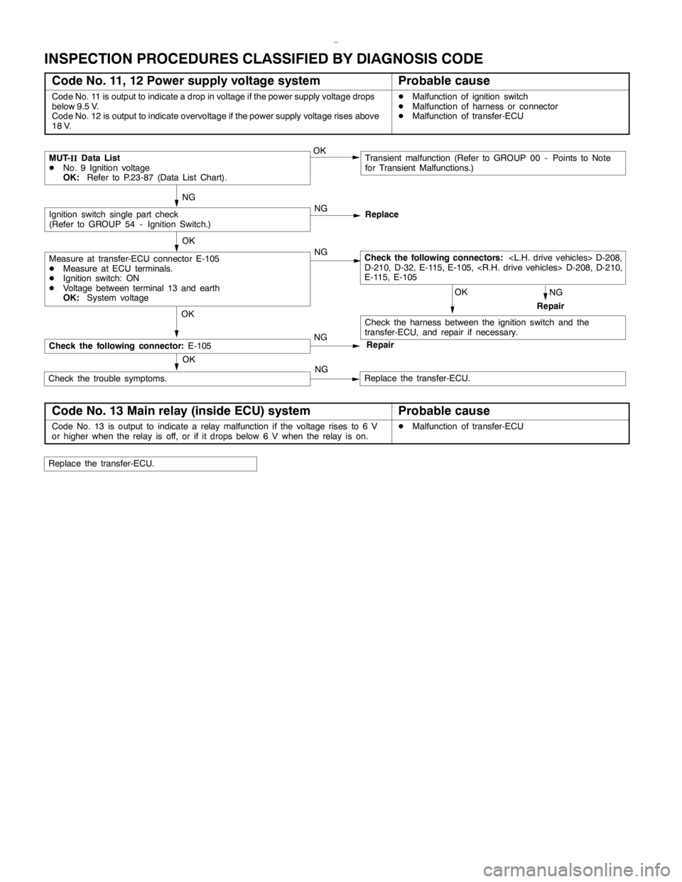
INSPECTION PROCEDURES CLASSIFIED BY DIAGNOSIS CODE
Code No. 11, 12 Power supply voltage systemProbable cause
Code No. 11 is output to indicate a drop in voltage if the power supply voltage drops
below 9.5 V.
Code No. 12 is output to indicate overvoltage if the power supply voltage rises above
18 V.DMalfunction of ignition switch
DMalfunction of harness or connector
DMalfunction of transfer-ECU
NG OK
OK
Repair NG
Replace
NG
Ignition switch single part check
(Refer to GROUP 54 - Ignition Switch.)
Check the following connectors:
D-210, D-32, E-115, E-105,
E-115, E-105
Repair
Transient malfunction (Refer to GROUP 00 - Points to Note
for Transient Malfunctions.)
Measure at transfer-ECU connector E-105
DMeasure at ECU terminals.
DIgnition switch: ON
DVoltage between terminal 13 and earth
OK:System voltage
Check the harness between the ignition switch and the
transfer-ECU, and repair if necessary.
OK
Replace the transfer-ECU. OKOK NG
NGCheck the trouble symptoms.
MUT-
IIData List
DNo. 9 Ignition voltage
OK:Refer to P.23-87 (Data List Chart).
NG
Check the following connector:E-105
Code No. 13 Main relay (inside ECU) systemProbable cause
Code No. 13 is output to indicate a relay malfunction if the voltage rises to 6 V
or higher when the relay is off, or if it drops below 6 V when the relay is on.DMalfunction of transfer-ECU
Replace the transfer-ECU.
www.WorkshopManuals.co.uk
Purchased from www.WorkshopManuals.co.uk
Page 974 of 1839
AUTOMATIC TRANSMISSION -Troublehshooting
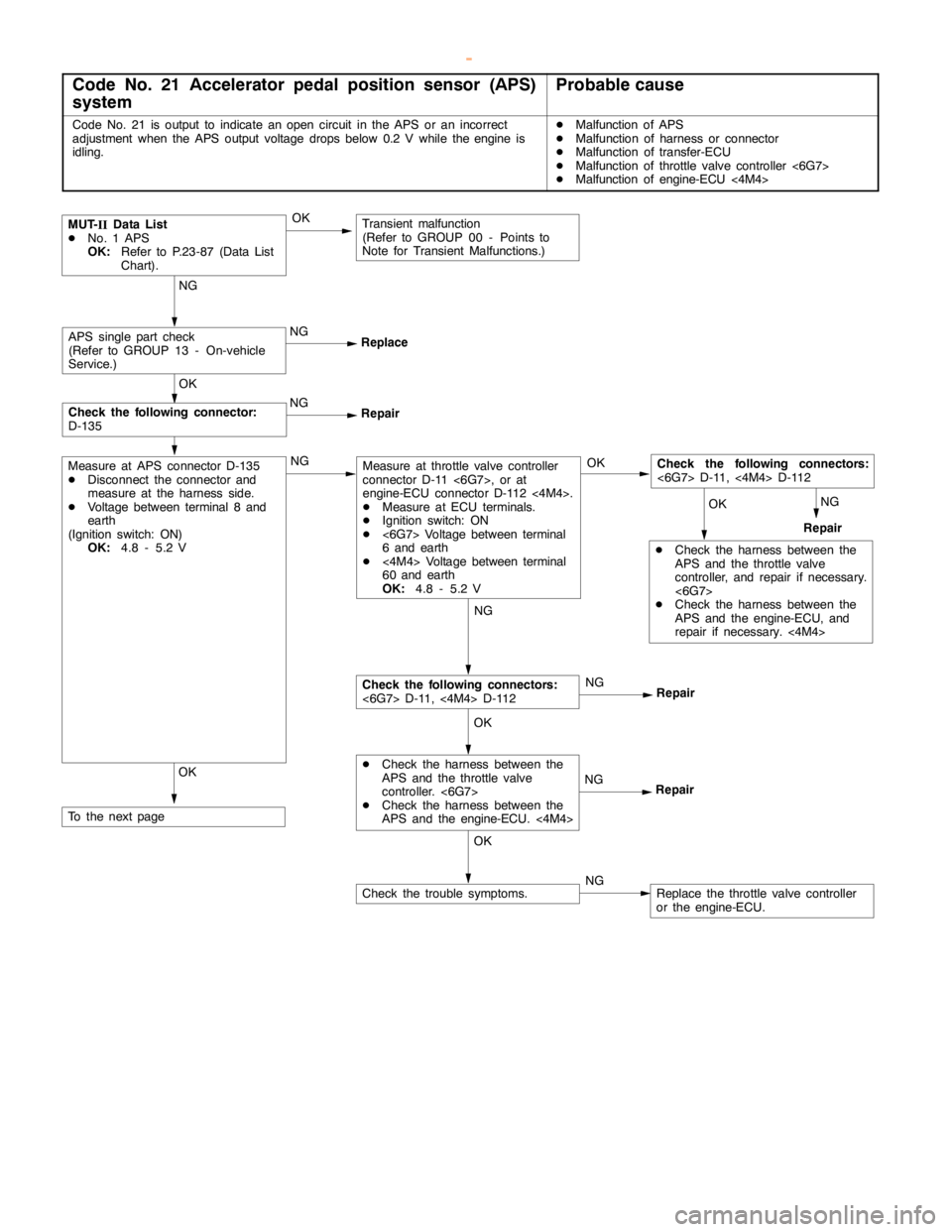
Code No. 21 Accelerator pedal position sensor (APS)
systemProbable cause
Code No. 21 is output to indicate anopencircuit in the APS or an incorrect
adjustment when the APS output voltage drops below 0.2 V while theengine is
idling.DMalfunction of APS
DMalfunction of harness or connector
DMalfunction of transfer-ECU
DMalfunction of throttle valve controller <6G7>
DMalfunction of engine-ECU <4M4>
NGNG
NG
Repair
MUT-
IIData List
DNo. 1 APS
OK:Refer to P.23-87 (Data List
Chart).
NG
ReplaceAPS single part check
(Refer to GROUP 13 - On-vehicle
Service.)
OK
NG
Repair
OK
Check the following connector:
D-135
OK
DCheck the harness between the
APS and the throttle valve
controller, and repair if necessary.
<6G7>
DCheck the harness between the
APS and the engine-ECU, and
repair if necessary.<4M4> OK
Check the following connectors:
<6G7> D-11,<4M4> D-112
Repair
NG
Repair
NG
Repair
OK
DCheck the harness between the
APS and the throttle valve
controller. <6G7>
DCheck the harness between the
APS and the engine-ECU. <4M4>
OK
Check the following connectors:
<6G7> D-11,<4M4> D-112
Measure at throttle valve controller
connector D-11 <6G7>, or at
engine-ECU connector D-112 <4M4>.
DMeasure at ECU terminals.
DIgnition switch: ON
D<6G7> Voltage between terminal
6 and earth
D<4M4> Voltage between terminal
60 and earth
OK:4.8 - 5.2 V
NGNG
NGCheck the trouble symptoms.Replace the throttle valve controller
or the engine-ECU.
OK
Measure at APS connector D-135
DDisconnect the connector and
measure at the harness side.
DVoltage between terminal 8 and
earth
(Ignition switch: ON)
OK:4.8 - 5.2 V
To the nextpage
Transient malfunction
(Refer to GROUP 00 - Points to
Note for Transient Malfunctions.)
OK
www.WorkshopManuals.co.uk
Purchased from www.WorkshopManuals.co.uk
Page 975 of 1839
AUTOMATIC TRANSMISSION -Troublehshooting
OKOK OK
NG
NG
NG(1)NGCheck the following connectors:
<6G7> D-11,<4M4> D-112
Repair OK
DCheck the harness between the
APS and the throttle valve
controller, and repair if necessary.
<6G7>
DCheck the harness between the
APS and the engine-ECU, and
repair if necessary.<4M4> OK (2)NG
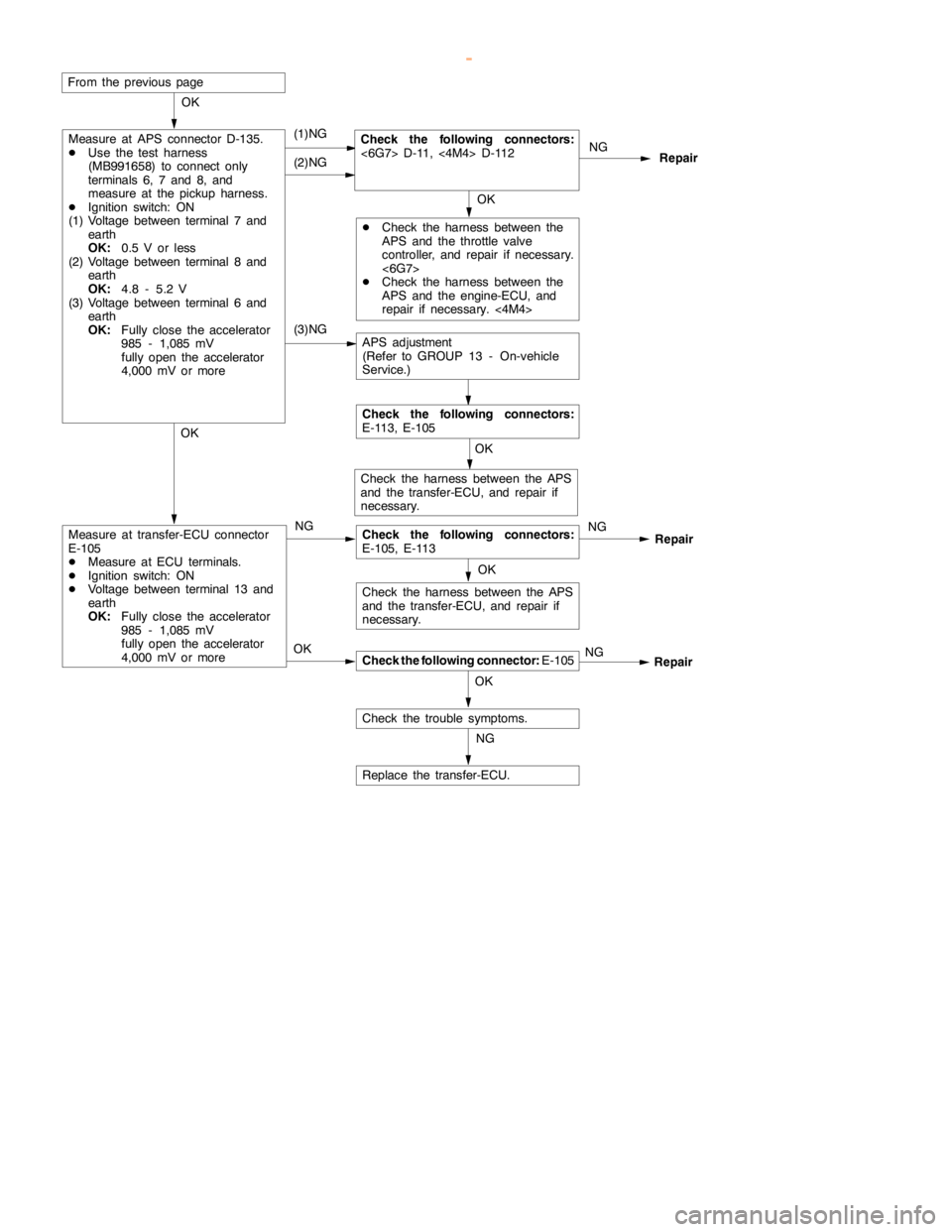
Measure at transfer-ECU connector
E-105
DMeasure at ECU terminals.
DIgnition switch: ON
DVoltage between terminal 13 and
earth
OK:Fully close the accelerator
985 - 1,085 mV
fullyopen the accelerator
4,000 mV or more
Check the following connector:E-105
Check the trouble symptoms.OK
Check the following connectors:
E-105, E-113 NG
Replace the transfer-ECU. OK
NGRepair
Check the harness between the APS
and the transfer-ECU, and repair if
necessary.
Check the harness between the APS
and the transfer-ECU, and repair if
necessary.
From the previouspage
(3)NG
Measure at APS connector D-135.
DUse the test harness
(MB991658) to connect only
terminals 6, 7 and 8, and
measure at the pickup harness.
DIgnition switch: ON
(1) Voltage between terminal 7 and
earth
OK:0.5 V or less
(2) Voltage between terminal 8 and
earth
OK:4.8 - 5.2 V
(3) Voltage between terminal 6 and
earth
OK:Fully close the accelerator
985 - 1,085 mV
fullyopen the accelerator
4,000 mV or more
APS adjustment
(Refer to GROUP 13 - On-vehicle
Service.)
Check the following connectors:
E-113, E-105
Repair
www.WorkshopManuals.co.uk
Purchased from www.WorkshopManuals.co.uk
Page 976 of 1839
AUTOMATIC TRANSMISSION -Troublehshooting
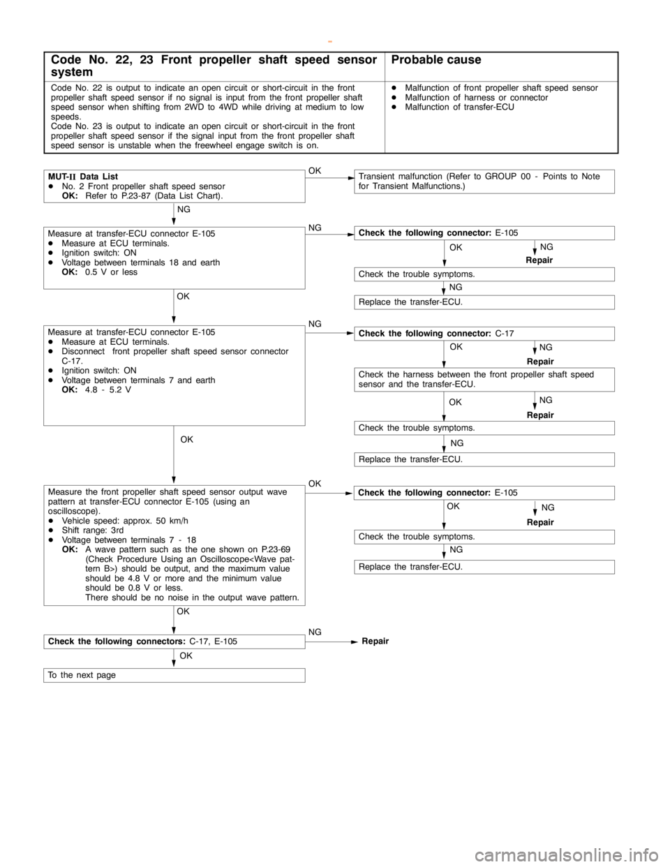
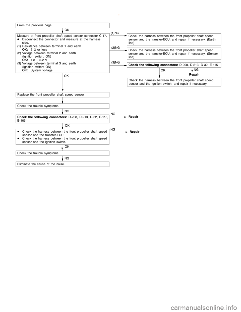
Code No. 22, 23 Front propeller shaft speed sensor
systemProbable cause
Code No. 22 is output to indicate anopencircuit or short-circuit in the front
propeller shaft speed sensor if no signal is input from the front propeller shaft
speed sensor when shifting from 2WD to 4WD while driving atmedium to low
speeds.
Code No. 23 is output to indicate anopencircuit or short-circuit in the front
propeller shaft speed sensor if the signal input from the front propeller shaft
speed sensor is unstable when the freewheelengageswitch is on.DMalfunction of front propeller shaft speed sensor
DMalfunction of harness or connector
DMalfunction of transfer-ECU
Transient malfunction (Refer to GROUP 00 - Points to Note
for Transient Malfunctions.)
OK NG
OK
OK
To the nextpage
NG
OK
NG
NG
Repair
Replace the transfer-ECU.
OKMUT-
IIData List
DNo. 2 Front propeller shaft speed sensor
OK:Refer to P.23-87 (Data List Chart).
OK
OK
NG
OK
Measure at transfer-ECU connector E-105
DMeasure at ECU terminals.
DIgnition switch: ON
DVoltage between terminals 18 and earth
OK:0.5 V or less
NG
Repair
Replace the transfer-ECU.
NG
Check the trouble symptoms.
Check the trouble symptoms.
Replace the transfer-ECU.
OK
OK
Measure at transfer-ECU connector E-105
DMeasure at ECU terminals.
DDisconnect front propeller shaft speed sensor connector
C-17.
DIgnition switch: ON
DVoltage between terminals 7 and earth
OK:4.8 - 5.2 V
Measure the front propeller shaft speed sensor output wave
pattern at transfer-ECU connector E-105 (using an
oscilloscope).
DVehicle speed: approx. 50 km/h
DShift range: 3rd
DVoltage between terminals 7 - 18
OK:A wave pattern such as the one shown on P.23-69
(Check Procedure Using an Oscilloscope
should be 4.8 V or more and the minimumvalue
should be 0.8 V or less.
There should be no noise in the output wave pattern.
NG
RepairCheck the following connectors:C-17, E-105NG
NG
Repair
Check the following connector:E-105Repair
NG
Check the harness between the front propeller shaft speed
sensor and the transfer-ECU.
Check the following connector:C-17
Check the trouble symptoms.
Check the following connector:E-105
www.WorkshopManuals.co.uk
Purchased from www.WorkshopManuals.co.uk
Page 977 of 1839
AUTOMATIC TRANSMISSION -Troublehshooting
(2)NG
(3)NG
From the previouspage
(1)NG
OK
NG
Measure at front propeller shaft speed sensor connector C-17.
DDisconnect the connector and measure at the harness
side.
(1) Resistance between terminal 1 and earth
OK:2
Wor less
(2) Voltage between terminal 2 and earth
(Ignition switch: ON)
OK:4.8 - 5.2 V
(3) Voltage between terminal 3 and earth
(Ignition switch: ON)
OK:System voltage
Check the harness between the front propeller shaft speed
sensor and the ignition switch, and repair if necessary.
Check the following connectors:D-208, D-213, D-32, E-115
NG
Check the trouble symptoms.
Check the harness between the front propeller shaft speed
sensor and the transfer-ECU, and repair if necessary. (Earth
line)
Replace the front propeller shaft speed sensorOK
OK
Repair
Check the harness between the front propeller shaft speed
sensor and the transfer-ECU, and repair if necessary. (Sensor
line)
Eliminate the cause of the noise.
NG
Check the trouble symptoms.
NG
Repair
OK
NG
Repair
OK
DCheck the harness between the front propeller shaft speed
sensor and the transfer-ECU.
DCheck the harness between the front propeller shaft speed
sensor and the ignition switch.
Check the following connectors:D-208, D-213, D-32, E-115,
E-105
www.WorkshopManuals.co.uk
Purchased from www.WorkshopManuals.co.uk
Page 978 of 1839
AUTOMATIC TRANSMISSION -Troublehshooting
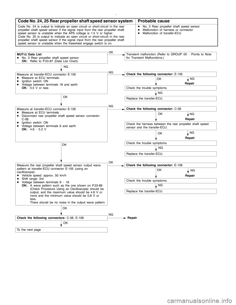
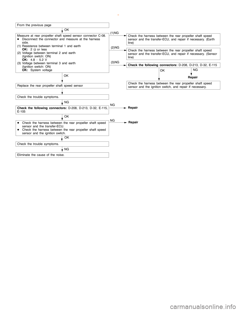
Code No. 24, 25 Rear propeller shaft speed sensor systemProbable cause
Code No. 24 is output to indicate anopencircuit or short-circuit in the rear
propeller shaft speed sensor if the signal input from the rear propeller shaft
speed sensor is unstable when the APS voltage is 1.5 V or higher.
Code No. 25 is output to indicate anopencircuit or short-circuit in the rear
propeller shaft speed sensor if the signal input from the rear propeller shaft
speed sensor is unstable when the freewheelengageswitch is on.DNo. 3 Rear propeller shaft speed sensor
DMalfunction of harness or connector
DMalfunction of transfer-ECU
Transient malfunction (Refer to GROUP 00 - Points to Note
for Transient Malfunctions.)
OK NG
Check the following connector:E-105
OK
OK
To the nextpage
NG
OK
NG
NG
Repair
Check the following connector:C-08
Replace the transfer-ECU.
OKMUT-
IIData List
DNo. 3 Rear propeller shaft speed sensor
OK:Refer to P.23-87 (Data List Chart).
OK
OK
NG
Check the trouble symptoms.
OK
Measure at transfer-ECU connector E-105
DMeasure at ECU terminals.
DIgnition switch: ON
DVoltage between terminals 18 and earth
OK:0.5 V or less
NG
Repair
Replace the transfer-ECU.
NG
Check the trouble symptoms.
Check the trouble symptoms.
Replace the transfer-ECU.
OK
OK
Measure at transfer-ECU connector E-105
DMeasure at ECU terminals.
DDisconnect rear propeller shaft speed sensor connector
C-08.
DIgnition switch: ON
DVoltage between terminals 9 and earth
OK:4.8 - 5.2 V
Measure the rear propeller shaft speed sensor output wave
pattern at transfer-ECU connector E-105 (using an
oscilloscope).
DVehicle speed: approx. 50 km/h
DShift range: 3rd
DVoltage between terminals 9 - 18
OK:A wave pattern such as the one shown on P.23-69
(Check Procedure Using an Oscilloscope) should be
output, and the maximum value should be 4.8 V or
more and the minimumvalue should be 0.8 V or
less.
There should be no noise in the output wave pattern.
NG
RepairCheck the following connectors:C-08, E-108NG
NG
Repair
Check the following connector:E-108Repair
NG
Check the harness between the rear propeller shaft speed
sensor and the transfer-ECU.
www.WorkshopManuals.co.uk
Purchased from www.WorkshopManuals.co.uk
Page 979 of 1839
AUTOMATIC TRANSMISSION -Troublehshooting
(2)NG
(3)NG
From the previouspage
(1)NG
OK
NG
Measure at rear propeller shaft speed sensor connector C-08.
DDisconnect the connector and measure at the harness
side.
(1) Resistance between terminal 1 and earth
OK:2
Wor less
(2) Voltage between terminal 2 and earth
(Ignition switch: ON)
OK:4.8 - 5.2 V
(3) Voltage between terminal 3 and earth
(Ignition switch: ON)
OK:System voltage
Check the harness between the rear propeller shaft speed
sensor and the ignition switch, and repair if necessary.
Check the following connectors:D-208, D-213, D-32, E-115
NG
Check the trouble symptoms.
Check the harness between the rear propeller shaft speed
sensor and the transfer-ECU, and repair if necessary. (Earth
line)
Replace the rear propeller shaft speed sensorOK
OK
Repair
Check the harness between the rear propeller shaft speed
sensor and the transfer-ECU, and repair if necessary. (Sensor
line)
Eliminate the cause of the noise.
NG
Check the trouble symptoms.
NG
Repair
OK
NG
Repair
OK
DCheck the harness between the rear propeller shaft speed
sensor and the transfer-ECU.
DCheck the harness between the rear propeller shaft speed
sensor and the ignition switch.
Check the following connectors:D-208, D-213, D-32, E-115,
E-105
www.WorkshopManuals.co.uk
Purchased from www.WorkshopManuals.co.uk
Page 980 of 1839
AUTOMATIC TRANSMISSION -Troublehshooting
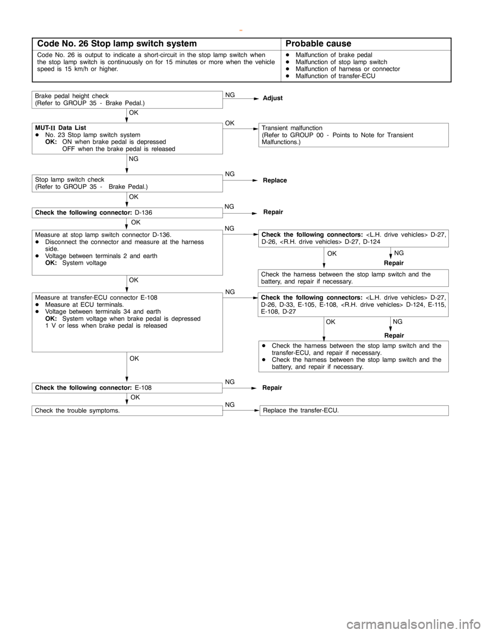
Code No. 26 Stop lamp switch systemProbable cause
Code No. 26 is output to indicate a short-circuit in the stoplampswitch when
the stoplampswitch is continuously on for 15 minutes or more when the vehicle
speed is 15 km/h or higher.DMalfunction of brakepedal
DMalfunction of stoplampswitch
DMalfunction of harness or connector
DMalfunction of transfer-ECU
NG
NG
NG
MUT-
IIData List
DNo. 23 Stoplampswitch system
OK:ON when brakepedal is depressed
OFF when the brakepedal is releasedTransient malfunction
(Refer to GROUP 00 - Points to Note for Transient
Malfunctions.) OK
OK OK OK NG
DCheck the harness between the stoplampswitch and the
transfer-ECU, and repair if necessary.
DCheck the harness between the stoplampswitch and the
battery, and repair if necessary.Repair
Check the harness between the stoplampswitch and the
battery, and repair if necessary.
OK OK
Brakepedal heightcheck
(Refer to GROUP 35 - Brake Pedal.)
OKNG
Adjust
OK
OK
NG
NG
Check the trouble symptoms.Replace the transfer-ECU.
Measure at transfer-ECU connector E-108
DMeasure at ECU terminals.
DVoltage between terminals 34 and earth
OK:System voltage when brakepedal is depressed
1 V or less when brakepedal is released
Measure at stoplampswitch connector D-136.
DDisconnect the connector and measure at the harness
side.
DVoltage between terminals 2 and earth
OK:System voltageNG
Replace
NG
Repair
Stoplampswitch check
(Refer to GROUP 35 - Brake Pedal.)
Check the following connector:D-136
Repair NG
Check the following connector:E-108Repair
Check the following connectors:
D-26, D-33, E-105, E-108,
E-108, D-27
Check the following connectors:
D-26,
www.WorkshopManuals.co.uk
Purchased from www.WorkshopManuals.co.uk