2000 MITSUBISHI MONTERO coolant
[x] Cancel search: coolantPage 303 of 1839

GDI -Troubleshooting
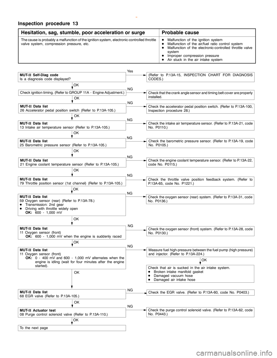
Inspection procedure 13
Hesitation, sag, stumble, poor acceleration or surge
Probable cause
The cause is probably a malfunction of the ignition system, electronic-controlled throttle
valve system, compression pressure, etc.DMalfunction of the ignition system
DMalfunction of the air/fuel ratio control system
DMalfunction of the electronic-controlled throttle valve
system
DImproper compression pressure
DAir stuck in the air intake system
MUT-
IISelf-Diag code
Is a diagnosis code displayed?Ye s(Refer to P.13A-15, INSPECTION CHART FOR DIAGNOSIS
CODES.)
OK
Check ignition timing. (Refer to GROUP 11A - Engine Adjustment.)NGCheck that the crankanglesensor andtiming beltcover are properly
installed.
OK
NG
Check the acceleratorpedal positionswitch. (Refer to P.13A-100,
Inspection procedure 28.)
OK
MUT-
IIData list
13 Intake air temperature sensor (Refer to P.13A-105.)NGCheck the intake air temperature sensor. (Refer to P.13A-21, code
No. P0110.)
OK
MUT-
IIData list
25 Barometric pressure sensor (Refer to P.13A-105.)NGCheck the barometric pressure sensor. (Refer to P.13A-19, code
No. P0105.)
OK
MUT-
IIData list
21 Engine coolant temperature sensor (Refer to P.13A-105.)NGCheck theengine coolant temperaturesensor. (Refer to P.13A-22,
code No. P0115.)
OK
MUT-
IIData list
79 Throttle position sensor (1st channel) (Refer to P.13A-105.)NGCheck the throttle valve position feedback system. (Refer to
P.13A-65, code No. P1221.)
OK
MUT-
IIData list
11 Oxygen sensor (front)
OK:
0 - 400 mV and 600 - 1,000 mV alternates when the
engine is idling(wait for four minutes after theengine
started).NGMeasure fuel high-pressure between the fuel pump (highpressure)
and injector. (Refer to P.13A-224.)
OK
MUT-
IIData list
11 Oxygen sensor (front)
OK:
600 - 1,000 mV when theengine is suddenlyracedNGCheck the oxygen sensor (front) system. (Refer to P.13A-28, code
No. P0130.)
OK
Check that air is sucked in the air intake system.
DBroken intake manifold gasket
DDamaged vacuum hose
DDamaged air intake hose
OK
MUT-
IIData list
68 EGR valve (Refer to P.13A-105.)NGCheck the EGR valve. (Refer to P.13A-60, code No. P0403.)
OK
MUT-
IIActuator test
08 Purge control solenoid valve (Refer to P.13A-110.)NGCheck the purge control solenoid valve. (Refer to P.13A-62, code
No. P0443.)
OK
To the nextpage
OK
MUT-
IIData list
59 Oxygen sensor (rear) (Refer to P.13A-78.)
DTransmission: 2nd gear
DDriving with throttle widelyopen
OK:
600 - 1,000 mVNGCheck the oxygen sensor (rear) system. (Refer to P.13A-31, code
No. P0136.)
MUT-
IIData list
26 Acceleratorpedal positionswitch (Refer to P.13A-105.)
www.WorkshopManuals.co.uk
Purchased from www.WorkshopManuals.co.uk
Page 306 of 1839

GDI -Troubleshooting
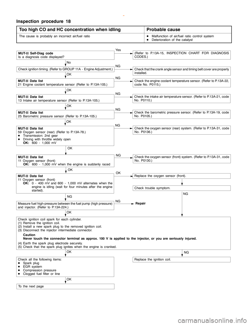
Inspection procedure 18
Too high CO and HC concentration when idling
Probable cause
The cause is probably an incorrect air/fuel ratioDMalfunction of air/fuel ratio control system
DDeterioration of the catalyst
MUT-
IISelf-Diag code
Is a diagnosis code displayed?Ye s(Refer to P.13A-15, INSPECTION CHART FOR DIAGNOSIS
CODES.)
No
Check ignition timing. (Refer to GROUP 11A - Engine Adjustment.)NGCheck that the crankanglesensor andtiming beltcover are properly
installed.
OK
MUT-
IIData list
21 Engine coolant temperature sensor (Refer to P.13A-105.)NGCheck theengine coolant temperaturesensor. (Refer to P.13A-22,
code No. P0115.)
OK
MUT-
IIData list
13 Intake air temperature sensor (Refer to P.13A-105.)NGCheck the intake air temperature sensor. (Refer to P.13A-21, code
No. P0110.)
OK
MUT-
IIData list
25 Barometric pressure sensor (Refer to P.13A-105.)NGCheck the barometric pressure sensor. (Refer to P.13A-19, code
No. P0105.)
OK
NG
Check the oxygen sensor (front) system. (Refer to P.13A-31, code
No. P0130.)
OK
MUT-
IIData list
11 Oxygen sensor (front)
OK:
0 - 400 mV and 600 - 1,000 mV alternates when the
engine is idling(wait for four minutes after theengine
started).OKReplace the oxygen sensor (front).
Check trouble symptom.
NGNG
Measure fuel high-pressure between the fuel pump (highpressure)
and injector. (Refer to P.13A-224.)NG
Repair
OK
Check ignition coil spark for each cylinder.
(1) Remove the ignition coil.
(2) Install a new sparkplug to the removed ignitioncoil.
(3) Disconnect the injector intermediate connector.
Caution
Never touch the connector terminal as approx. 100 V is applied to the injector, or you are seriously injured.
(4) Earth the sparkplug electrodesecurely.
(5) Check that the sparkplug igniteswhen theengine iscranked.
NG
Replace the ignition coil.
OK
Check all the following items:
DSparkplug
DEGR system
DCompression pressure
DClogged fuel filter or line
OK
To the nextpage
OK
MUT-
IIData list
59 Oxygen sensor (rear) (Refer to P.13A-78.)
DTransmission: 2nd gear
DDriving with throttle widelyopen
OK:
600 - 1,000 mVNGCheck the oxygen sensor (rear) system. (Refer to P.13A-31, code
No. P0136.)
MUT-
IIData list
11 Oxygen sensor (front)
OK:
600 - 1,000 mV when theengine is suddenlyraced
www.WorkshopManuals.co.uk
Purchased from www.WorkshopManuals.co.uk
Page 319 of 1839

GDI -Troubleshooting
DATA LIST REFERENCE TABLE
Caution
When shifting the select lever to D range, the brakes should be applied so that the vehicle does
not move forward.
NOTE
*
1: Within four minutes after starting the engine
*2: In a new vehicle [driven approximately 500 km or less], the injector drive time is sometimes 10%
longer than the standard time.
*
3: The accelerator pedal position switch normally turns off when the voltage of the accelerator pedal
position sensor (1st channel) is 200 - 600 mV higher than the voltage at the idle position. If the
accelerator pedal position switch turns back on after the accelerator pedal position sensor voltage
has risen by 100 mV and the throttle valve has opened, the accelerator pedal position switch and
the accelerator pedal position sensor (1st channel) need to be adjusted.
Item
No.Check itemsRequirementsNormal conditionInspection
procedure
No.Reference
page
11Oxygen sen-Engine: AfterIdling200 mV or lessK
1Code No.13A-28
sor
(front)warm-up
Sudden racing600 - 1,000 mV
P0130
2,500 r/min400 mV or less and
600 - 1,000 mV
alternates.
12Air flow sensorD
Engine coolant
temperature:Idling22 - 48 HzCode No.
P010013A-17
80 - 95_
C
D
Lamps, electric
cooling fan and2,500 r/min60 - 100 Hz
cooling fan and
all accessories:
OFF
D
Transmission:
Neutral
RacingFrequency in-
creases in re-
sponse to racing.
13Intake air tem-
perature sen-Ignition switch: ONIntake air tempera-
ture: - 20_
C-20_
CCode No.
P011013A-21
sor
Intake air tempera-
ture: 0_
C0_
C
Intake air tempera-
ture: 20_
C20_
C
Intake air tempera-
ture: 40_
C40_
C
Intake air tempera-
ture: 80_
C80_
C
www.WorkshopManuals.co.uk
Purchased from www.WorkshopManuals.co.uk
Page 320 of 1839

GDI -Troubleshooting
Item
No.Reference
page Inspection
procedure
No. Normal condition Requirements Check items
14Throttle posi-
tion sensorDEngine coolant
temperature:Release the accel-
erator pedal.4,000 mV or moreCode No.
P022513A-52
(2nd channel)80 - 95_C
DIgnition switch:
ON (Engine
stopped)
Depress the accel-
erator pedal gradu-
ally.Voltage decreases
in response to the
pedal depression.
Depress the accel-
erator pedal fully.400 - 600 mV
16Power supply
voltageIgnition switch: ONSystem voltageProcedure
No.2513A-98
18Cranking sig-Transmission: Neu-Engine: StoppedOFFProcedure13A-99
nal (Ignition
switch - ST)tral
Engine: CrankingON
No.27
21Engine coolant
temperature
sensorIgnition switch: ONEngine coolant
temperature:
-20_C-20_CCode No.
P011513A-22
Engine coolant
temperature: 0_C0_C
Engine coolant
temperature: 20_C20_C
Engine coolant
temperature: 40_C40_C
Engine coolant
temperature: 80_C80_C
22Crank angle
sensorDEngine: crank-
ing
DTachometer:
ConnectedCompare the engine
speed readings on
the tachometer and
the MUT-II.AccordCode No.
P033513A-56
DEngine: Idling
DAccelerator
pedal positionEngine coolant
temperature:
-20_C1,250 - 1,450 r/min
switch: ON
Engine coolant
temperature: 0_C1,100 - 1,300 r/min
Engine coolant
temperature: 20_C1,000 - 1,200 r/min
Engine coolant
temperature: 40_C900 - 1,100 r/min
Engine coolant
temperature: 80_C550 - 650 r/min*1
www.WorkshopManuals.co.uk
Purchased from www.WorkshopManuals.co.uk
Page 321 of 1839

GDI -Troubleshooting
Item
No.Reference
page Inspection
procedure
No. Normal condition Requirements Check items
25BarometricIgnition switch: ONAltitude: 0 m101 kPaCode No.13A-19
pressure sen-
sor
Altitude: 600 m95 kPa
P0105
Altitude: 1,200 m88 kPa
Altitude: 1,800 m81 kPa
26Accelerator
pedal positionIgnition switch: ON
(Depress and re-Release the accel-
erator pedal.ONProcedure
No.2813A-100
switchlease the accelera-
tor pedal several
times)
Depress the accel-
erator pedal slight-
ly.OFF
27Power steer-
ing fluid pres-Engine: IdlingSteering wheel sta-
tionaryOFFProcedure
No.3013A-102
sure switch
Steering wheel
turningON
28A/C switchEngine: Idling (The
A/C compressor isA/C switch: OFFOFFProcedure
No.3113A-100
A/C compressor is
running when the
A/C switch is on.)
A/C switch: ONON
No.31
31Small lamp
switchEngine: IdlingLighting switch:
OFFOFFProcedure
No.3313A-104
Lighting switch: ONON
34Air flow sensorEngine: After hav-Engine is idlingONCode No.13A-17
reset signaling warmed up
3,000 r/minOFF
P0100
37Volumetric effi-
ciencyDEngine coolant
temperature:Engine is idling20 - 40%--
80 - 95_C
DLamps, electric
cooling fan and2,500 r/min10 - 30%
cooling fan and
all accessories:
OFF
DTransmission:
Neutral
Engine is suddenly
racedVolumetric effi-
ciency increases in
response to racing
38Crank angle
sensorDEngine: Cranking [reading is possible
at 2,000 r/min or less]
DTachometer: ConnectedEngine speeds dis-
played on the
MUT-IIand
tachometer are
identical.--
www.WorkshopManuals.co.uk
Purchased from www.WorkshopManuals.co.uk
Page 322 of 1839

GDI -Troubleshooting
Item
No.Reference
page Inspection
procedure
No. Normal condition Requirements Check items
41Injector drive
time *2DEngine coolant
temperature:
80 - 95_CIdling0.3 - 0.8 ms*1--
80 - 95_C
DLamps, electric
cooling fan and
all accessories:
2,500 r/min0.4 - 1.0 ms
all accessories:
OFF
DTransmission:
Neutral
Sudden racingIncreases
44Ignition
advanceDEngine: After
warm-upIdling5-20_BTDC *1Code No.
P030013A-53
advancewarm-up
DSet a timing
light.
2,500 r/min15 - 35_BTDC
P0300
49A/C relayEngine: After
warm-up, idlingA/C switch: OFFOFF (compressor
clutch is not oper-
ating)Procedure
No.3113A-102
A/C switch: ONON (compressor
clutch is operating)
59Oxygen sen-
sor (rear)DTransmission:
2nd gear
DDrive with
throttle widely
open3,500 r/min600 - 1,000 mVCode No.
P013613A-31
67Stop lamp
switchIgnition switch: ONBrake pedal: De-
pressedOFFProcedure
No.3213A-103
Brake pedal: Re-
leasedON
68EGR valveDEngine coolant
temperature:
80 - 95_C
DLamps, electricIdling2 - 20 STEPCode No.
P040313A-60
cooling fan and
all accessories:
OFF
DTransmission:
Neutral
2,500 r/min0 - 10 STEP
74Fuel pressure
sensorDEngine coolant
temperature:
80 - 95_C
DLamps, electric
cooling fan and
all accessories:
OFF
DTransmission:
NeutralEngine: Idling4 - 6.9 MPaCode No.
P019013A-36
www.WorkshopManuals.co.uk
Purchased from www.WorkshopManuals.co.uk
Page 323 of 1839

GDI -Troubleshooting
Item
No.Reference
page Inspection
procedure
No. Normal condition Requirements Check items
77Accelerator
pedal positionIgnition switch: ONRelease the accel-
erator pedal.985 - 1085 mVCode
No.P122513A-68
sensor (2nd
channel)
Depress the accel-
erator pedal gradu-
ally.Increases in re-
sponse to the ped-
al depression
stroke.
Depress the accel-
erator pedal fully.4,000 mV or more
78Accelerator
pedal positionIgnition switch: ONRelease the accel-
erator pedal.985 - 1085 mVCode
No.P022013A-50
sensor (1st
channel) *3Depress the accel-
erator pedal gradu-
ally.Increases in re-
sponse to pedal
depression stroke.
Depress the accel-
erator pedal fully.4,200 - 4,800 mV
79Throttle posi-
tion sensorDEngine coolant
temperature:Release the accel-
erator pedal.400 - 800 mVCode
No.012013A-25
(1st channel)80 - 95_C
DIgnition switch:
ON (Engine
stopped)
Depress the accel-
erator pedal gradu-
ally.Increases in re-
sponse to pedal
depression stroke.
4,600 - 5,200 mV4,200 - 4,800 mV
Engine: AfterNo load450 - 1,000 mV
warm-up, idling
A/C switch: OFF®
ONIncreases by 100 -
600 mV.
99Fuel injection
modeEngine: After warm
upIdling (after four
minutes or more
have passed since
engine start)Lean compression--
2,500 r/minStoichiometric
metric feedback
Sudden racing after
idle positionOpen loop
www.WorkshopManuals.co.uk
Purchased from www.WorkshopManuals.co.uk
Page 326 of 1839

GDI -Troubleshooting
Terminal
No.Normal condition Check requirements (engine condition) Check item
16Purge control solenoid valveDEngine cool-Engine: stoppedSystem voltage
ant tempera-
ture:
80 - 95_C
DIgnition
switch: ON
Engine: Start the
engine, and then
increase engine
speed up to 3,500
r/min.Voltage decreases.
18Condenser fan relayCondenser fan is not operating.System voltage
Condenser fan is operating.0-3V
20Fuel pump relayIgnition switch:Engine: stoppedSystem voltage
ON
Engine: idling0-3V
21A/C relayDEngine: idlingSystem voltage, or changes
DA/C switch: OFF®ON
(Compressor is operating)from momentarily 6 V or
more to 0®3V
31Engine warning lampIgnition switch: OFF®ON0-3V®System voltage
(after several seconds)
41Sensor power supplyIgnition switch: ON4.5 - 5.5 V
42Power supply to accelerator
pedal position sensor (1st
channel)Ignition switch: ON4.5 - 5.5 V
43Crank angle sensorEngine: Cranking0.4 - 4.0 V
Engine: Idling1.5 - 2.5 V
44Engine coolant temperature
sensorIgnition switch:
ONEngine coolant
temperature: 0_C3.2 - 3.5 V
Engine coolant
temperature:
20_C2.3 - 2.9 V
Engine coolant
temperature:
40_C1.5 - 2.1 V
Engine coolant
temperature:
80_C0.4 - 1.0 V
45Engine ignition signalEngine: 3,000 r/min0.3 - 3.0 V
www.WorkshopManuals.co.uk
Purchased from www.WorkshopManuals.co.uk