2000 MITSUBISHI MONTERO coolant
[x] Cancel search: coolantPage 247 of 1839
GDI -Troubleshooting
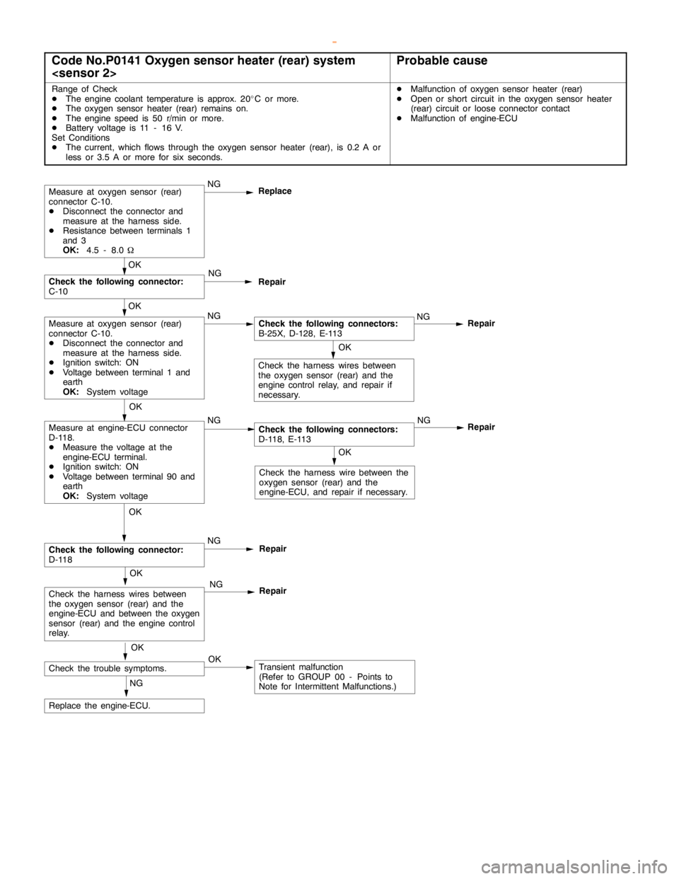
Code No.P0141 Oxygen sensor heater (rear) system
Range of Check
DThe engine coolant temperature is approx. 20_C or more.
DThe oxygen sensor heater (rear) remains on.
DThe enginespeed is 50 r/min or more.
DBattery voltage is 11 - 16 V.
Set Conditions
DThe current, which flows through the oxygen sensor heater (rear), is 0.2 A or
less or 3.5 A or more for six seconds.DMalfunction of oxygen sensor heater (rear)
DOpen or short circuit in the oxygen sensor heater
(rear) circuit or loose connector contact
DMalfunction of engine-ECU
OK
Check the harness wire between the
oxygen sensor (rear) and the
engine-ECU, and repair if necessary.
Repair
OK
Measure at engine-ECU connector
D-118.
DMeasure the voltage at the
engine-ECU terminal.
DIgnition switch: ON
DVoltage between terminal 90 and
earth
OK:
System voltageNGCheck the following connectors:
D-118, E-113NG
OK
Check the harness wires between
the oxygen sensor (rear) and the
engine controlrelay, and repair if
necessary.
Measure at oxygen sensor (rear)
connector C-10.
DDisconnect the connector and
measure at the harness side.
DResistance between terminals 1
and 3
OK:
4.5 - 8.0WNG
Replace
Repair
OK
Measure at oxygen sensor (rear)
connector C-10.
DDisconnect the connector and
measure at the harness side.
DIgnition switch: ON
DVoltage between terminal 1 and
earth
OK:
System voltageNGCheck the following connectors:
B-25X, D-128, E-113NG
OK
Check the following connector:
C-10NG
Repair
OK
Check the trouble symptoms.OKTransient malfunction
(Refer to GROUP 00 - Points to
Note for Intermittent Malfunctions.) NG
Replace the engine-ECU.
OK
Check the following connector:
D-118NG
Repair
OK
Check the harness wires between
the oxygen sensor (rear) and the
engine-ECU and between the oxygen
sensor (rear) and theengine control
relay.NG
Repair
www.WorkshopManuals.co.uk
Purchased from www.WorkshopManuals.co.uk
Page 248 of 1839
GDI -Troubleshooting
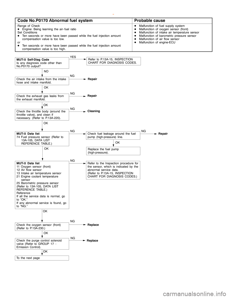
Code No.P0170 Abnormal fuel systemProbable cause
Range of Check
DEngine: Being learning the air - fuel ratio
Set Conditions
DTen seconds or more havebeenpassed while the fuel injection amount
compensation value is too low.
or
DTen seconds or more havebeenpassed while the fuel injection amount
compensation value is too high.DMalfunction of fuel supply system
DMalfunction of oxygen sensor (front)
DMalfunction of intake air temperature sensor
DMalfunction of barometric pressure sensor
DMalfunction of air flow sensor
DMalfunction of engine-ECU
Repair
OK
MUT-
IIData list
74 Fuel pressure sensor (Refer to
13A-105, DATA LIST
REFERENCE TABLE.)NGCheck fuel leakage around the fuel
pump (high-pressure) line.NG
NO
Check the air intake from the intake
hose and intake manifold.NG
Repair
OK
Check the oxygen sensor (front)
(Refer to P.13A-230.)NG
Replace
MUT-
IISelf-Diag Code
Is any diagnosis code other than
No.P0170 output?YESRefer to P.13A-15, INSPECTION
CHART FOR DIAGNOSIS CODES.
OK
Check the exhaust gas leaks from
the exhaust manifold.NG
Repair
OK
Check the throttle body (around the
throttle valve), and clean if
necessary. (Refer to P.13A-220).NG
Cleaning
OK
MUT-
IIData list
11 Oxygen sensor (front)
12 Air flow sensor
13 Intake air temperature sensor
21 Engine coolant temperature
sensor
25 Barometric pressure sensor
(Refer to 13A-105, DATA LIST
REFERENCE TABLE.)
Reference
If all the service data is normal, go
to “OK.”
If any abnormal service is found, go
to “NG.”NGRefer to the Inspection procedure for
the sensor, which is indicated by the
abnormal service data.
(Refer to P.13A-15, INSPECTION
CHART FOR DIAGNOSIS CODES.)OK
Replace the fuel pump
(high-pressure).
Check the purge control solenoid
valve (Refer to GROUP 17 -
Emission Control).NG
Replace
OK
To the nextpageOK
www.WorkshopManuals.co.uk
Purchased from www.WorkshopManuals.co.uk
Page 291 of 1839
GDI -Troubleshooting
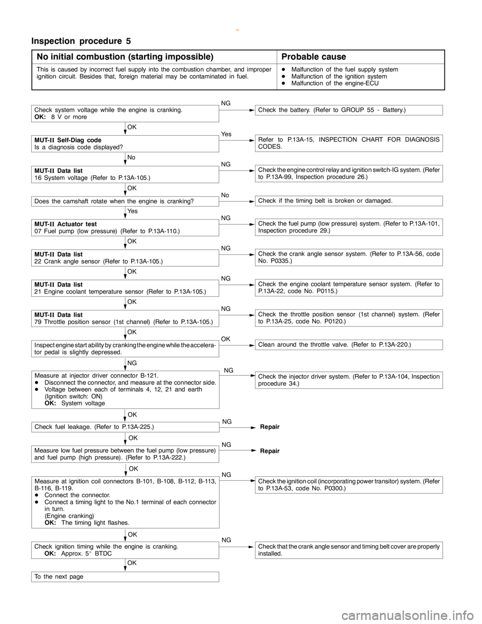
Inspection procedure 5
No initial combustion (starting impossible)
Probable cause
This is caused by incorrect fuel supply into the combustion chamber, and improper
ignition circuit. Besides that, foreign material may be contaminated in fuel.DMalfunction of the fuel supply system
DMalfunction of the ignition system
DMalfunction of the engine-ECU
Check system voltage while theengine iscranking.
OK:
8 V or moreNGCheck the battery. (Refer to GROUP 55 - Battery.)
OK
MUT-
IISelf-Diag code
Is a diagnosis code displayed?Ye sRefer to P.13A-15, INSPECTION CHART FOR DIAGNOSIS
CODES.
No
MUT-
IIData list
16 System voltage (Refer to P.13A-105.)NGCheck theengine controlrelay and ignition switch-IG system. (Refer
to P.13A-99, Inspection procedure 26.)
OK
Does the camshaft rotate when theengine is cranking?NoCheck if thetiming belt isbroken ordamaged.
Ye s
MUT-
IIActuator test
07 Fuel pump(low pressure) (Refer to P.13A-110.)NGCheck the fuelpump(low pressure) system. (Refer to P.13A-101,
Inspection procedure 29.)
OK
MUT-
IIData list
22 Crankanglesensor (Refer to P.13A-105.)NGCheck the crankanglesensor system. (Refer to P.13A-56, code
No. P0335.)
OK
MUT-
IIData list
21 Engine coolant temperature sensor (Refer to P.13A-105.)NGCheck theengine coolant temperaturesensor system. (Refer to
P.13A-22, code No. P0115.)
OK
MUT-
IIData list
79 Throttle position sensor (1st channel) (Refer to P.13A-105.)NGCheck the throttle position sensor (1st channel) system. (Refer
to P.13A-25, code No. P0120.)
OK
Inspectenginestart ability by cranking theengine while theaccelera-
tor pedal isslightly depressed.OKClean around the throttle valve. (Refer to P.13A-220.)
NG
Check fuel leakage. (Refer to P.13A-225.)NG
Repair
OK
Measure low fuel pressure between the fuelpump(low pressure)
and fuel pump (highpressure). (Refer to P.13A-222.)NG
Repair
OK
Measure at ignition coil connectors B-101, B-108, B-112, B-113,
B-116, B-119.
DConnect the connector.
DConnect atiming light to theNo.1 terminal of each connector
in turn.
(Engine cranking)
OK:
The timing lightflashes.NGCheck the ignition coil (incorporating power transitor) system. (Refer
to P.13A-53, code No. P0300.)
OK
Check ignitiontiming while the engine iscranking.
OK:
Approx. 5_BTDCNGCheck that the crankanglesensor andtiming beltcover are properly
installed.
OK
To the nextpage
Measure at injector driver connector B-121.
DDisconnect the connector, and measure at the connector side.
DVoltage between each of terminals 4, 12, 21 and earth
(Ignition switch: ON)
OK:
System voltageCheck the injector driver system. (Refer to P.13A-104, Inspection
procedure 34.) NG
OK
www.WorkshopManuals.co.uk
Purchased from www.WorkshopManuals.co.uk
Page 293 of 1839
GDI -Troubleshooting
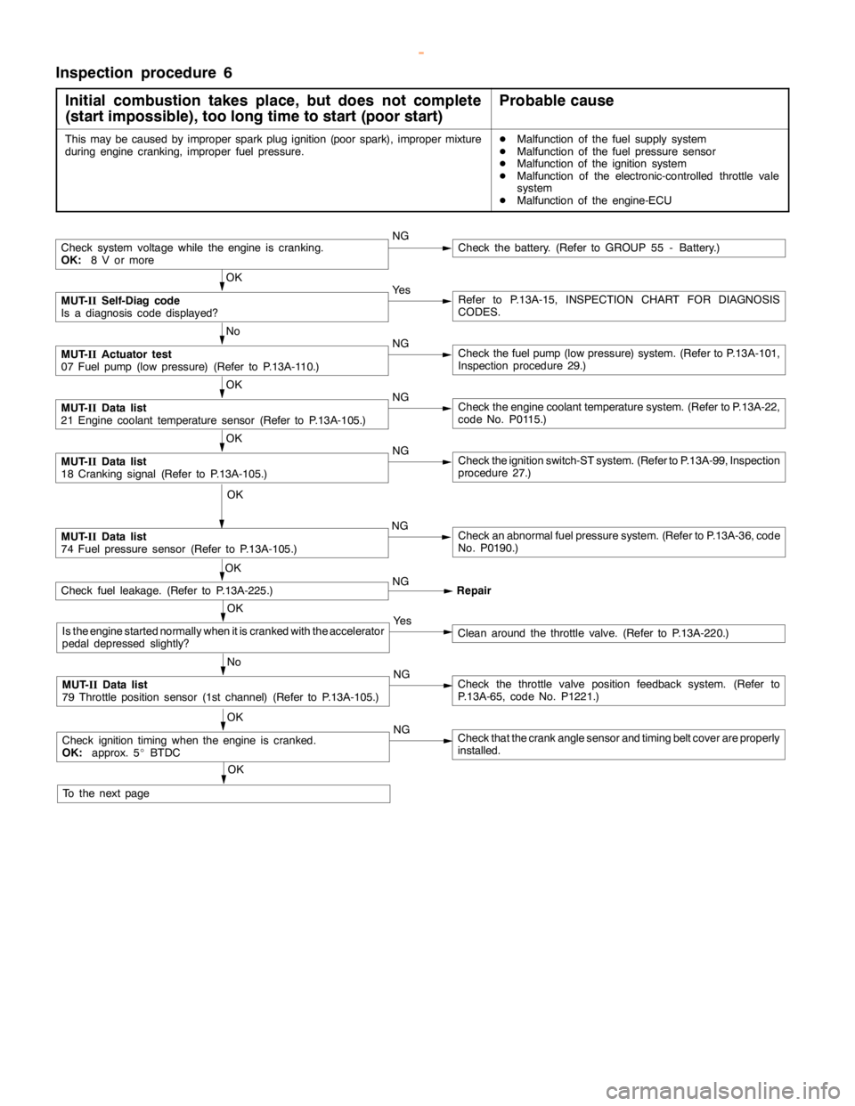
Inspection procedure 6
Initial combustion takes place, but does not complete
(start impossible), too long time to start (poor start)
Probable cause
This may be caused by improper sparkplug ignition (poorspark), improper mixture
during enginecranking, improper fuel pressure.DMalfunction of the fuel supply system
DMalfunction of the fuel pressure sensor
DMalfunction of the ignition system
DMalfunction of the electronic-controlled throttle vale
system
DMalfunction of the engine-ECU
Check system voltage while theengine iscranking.
OK:
8 V or moreNGCheck the battery. (Refer to GROUP 55 - Battery.)
OK
MUT-
IISelf-Diag code
Is a diagnosis code displayed?Ye sRefer to P.13A-15, INSPECTION CHART FOR DIAGNOSIS
CODES.
No
MUT-
IIActuator test
07 Fuel pump(low pressure) (Refer to P.13A-110.)NGCheck the fuelpump(low pressure) system. (Refer to P.13A-101,
Inspection procedure 29.)
OK
MUT-
IIData list
21 Engine coolant temperature sensor (Refer to P.13A-105.)NGCheck theengine coolant temperaturesystem. (Refer to P.13A-22,
code No. P0115.)
OK
MUT-
IIData list
18 Cranking signal (Refer to P.13A-105.)NGCheck the ignition switch-ST system. (Refer to P.13A-99, Inspection
procedure 27.)
OK
MUT-
IIData list
74 Fuel pressure sensor (Refer to P.13A-105.)NGCheck an abnormal fuel pressure system. (Refer to P.13A-36, code
No. P0190.)
Check fuel leakage. (Refer to P.13A-225.)NG
Repair
OK
Is the enginestarted normally when it is cranked with the accelerator
pedal depressed slightly?Ye sClean around the throttle valve. (Refer to P.13A-220.)
No
MUT-
IIData list
79 Throttle position sensor (1st channel) (Refer to P.13A-105.)NGCheck the throttle valve position feedback system. (Refer to
P.13A-65, code No. P1221.)
OK
Check ignitiontimingwhen theengine iscranked.
OK:
approx. 5_BTDCNGCheck that the crankanglesensor andtiming beltcover are properly
installed.
OK
To the nextpageOK
www.WorkshopManuals.co.uk
Purchased from www.WorkshopManuals.co.uk
Page 295 of 1839
GDI -Troubleshooting
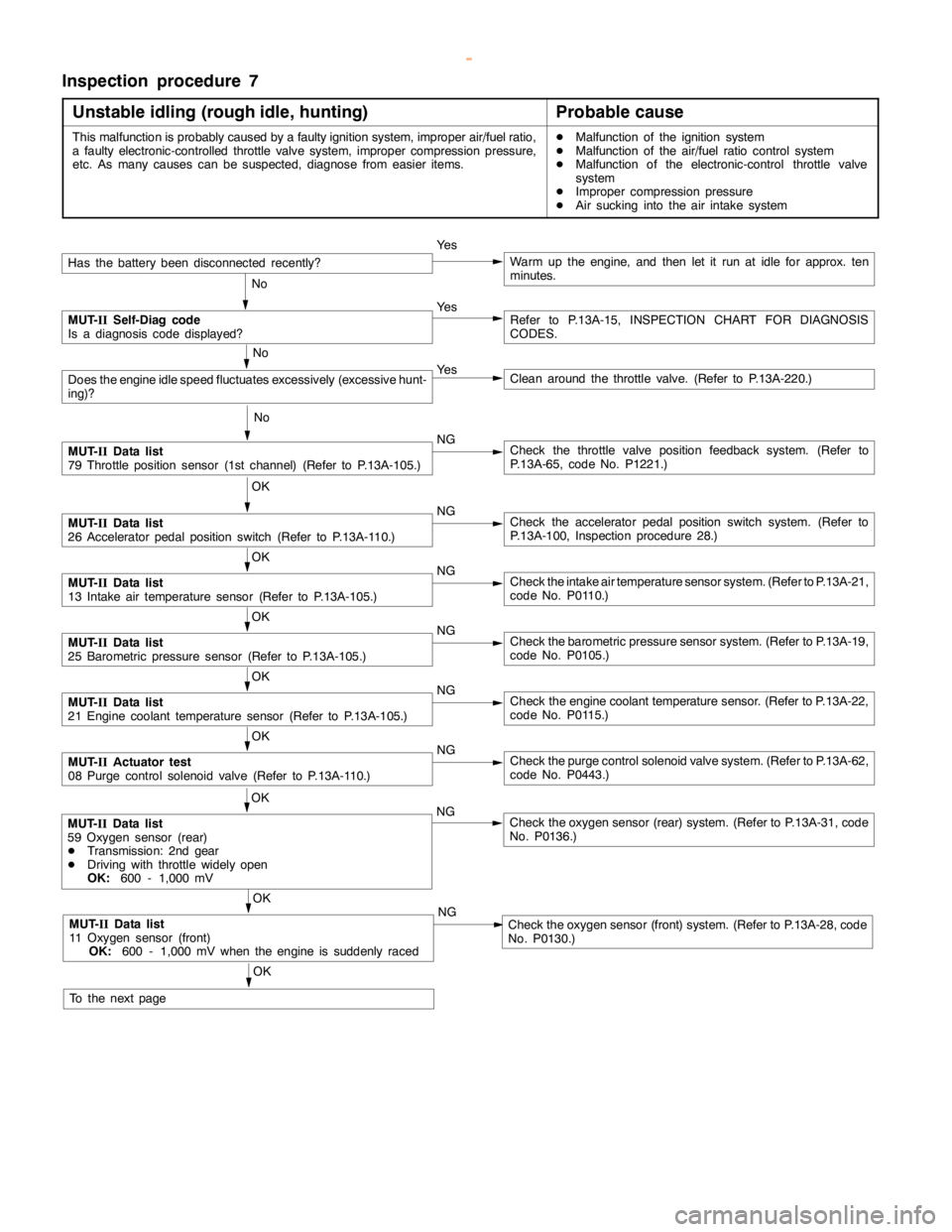
Inspection procedure 7
Unstable idling (rough idle, hunting)
Probable cause
This malfunction is probably caused by a faulty ignition system, improper air/fuel ratio,
a faulty electronic-controlled throttle valve system, improper compression pressure,
etc. As many causes can be suspected, diagnose from easier items.DMalfunction of the ignition system
DMalfunction of the air/fuel ratio control system
DMalfunction of the electronic-control throttle valve
system
DImproper compression pressure
DAir sucking into the air intake system
Has the batterybeen disconnectedrecently?Ye sWarm up the engine, and then let it run at idle for approx. ten
minutes.
No
MUT-
IISelf-Diag code
Is a diagnosis code displayed?Ye sRefer to P.13A-15, INSPECTION CHART FOR DIAGNOSIS
CODES.
No
Does theengine idlespeed fluctuates excessively (excessivehunt-
ing)?Ye sClean around the throttle valve. (Refer to P.13A-220.)
No
MUT-
IIData list
79 Throttle position sensor (1st channel) (Refer to P.13A-105.)NGCheck the throttle valve position feedback system. (Refer to
P.13A-65, code No. P1221.)
OK
MUT-
IIData list
26 Acceleratorpedal positionswitch (Refer to P.13A-110.)NGCheck the acceleratorpedal positionswitch system. (Refer to
P.13A-100, Inspection procedure 28.)
OK
MUT-
IIData list
13 Intake air temperature sensor (Refer to P.13A-105.)NGCheck the intake air temperature sensor system. (Refer to P.13A-21,
code No. P0110.)
OK
MUT-
IIData list
25 Barometric pressure sensor (Refer to P.13A-105.)NGCheck the barometric pressure sensor system. (Refer to P.13A-19,
code No. P0105.)
OK
MUT-
IIData list
21 Engine coolant temperature sensor (Refer to P.13A-105.)NGCheck theengine coolant temperaturesensor. (Refer to P.13A-22,
code No. P0115.)
OK
MUT-
IIActuator test
08 Purge control solenoid valve (Refer to P.13A-110.)NGCheck the purge control solenoid valve system. (Refer to P.13A-62,
code No. P0443.)
OK
MUT-
IIData list
11 Oxygen sensor (front)
OK:
600 - 1,000 mV when theengine is suddenlyracedNGCheck the oxygen sensor (front) system. (Refer to P.13A-28, code
No. P0130.)
OK
MUT-
IIData list
59 Oxygen sensor (rear)
DTransmission: 2nd gear
DDriving with throttle widelyopen
OK:
600 - 1,000 mVNGCheck the oxygen sensor (rear) system. (Refer to P.13A-31, code
No. P0136.)
OK
To the nextpage
www.WorkshopManuals.co.uk
Purchased from www.WorkshopManuals.co.uk
Page 297 of 1839
GDI -Troubleshooting
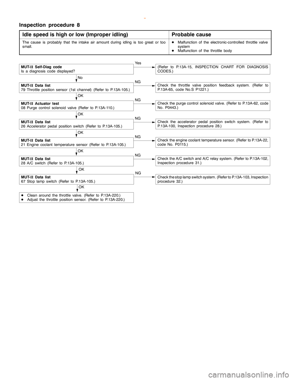
Inspection procedure 8
Idle speed is high or low (Improper idling)
Probable cause
The cause is probably that the intake airamount during idling is too great or too
small.DMalfunction of the electronic-controlled throttle valve
system
DMalfunction of the throttle body
MUT-
IISelf-Diag code
Is a diagnosis code displayed?Ye s(Refer to P.13A-15, INSPECTION CHART FOR DIAGNOSIS
CODES.)
No
MUT-
IIData list
79 Throttle position sensor (1st channel) (Refer to P.13A-105.)NGCheck the throttle valve position feedback system. (Refer to
P.13A-65, code No.S P1221.)
OK
MUT-
IIActuator test
08 Purge control solenoid valve (Refer to P.13A-110.)NGCheck the purge control solenoid valve. (Refer to P.13A-62, code
No. P0443.)
OK
MUT-
IIData list
26 Acceleratorpedal positionswitch (Refer to P.13A-105.)NGCheck the acceleratorpedal positionswitch system. (Refer to
P.13A-100, Inspection procedure 28.)
OK
MUT-
IIData list
21 Engine coolant temperature sensor (Refer to P.13A-105.)NGCheck theengine coolant temperaturesensor. (Refer to P.13A-22,
code No. P0115.)
OK
MUT-
IIData list
28 A/C switch (Refer to P.13A-105.)NGCheck the A/C switch and A/C relay system. (Refer to P.13A-102,
Inspection procedure 31.)
OK
MUT-
IIData list
67 Stoplampswitch (Refer to P.13A-105.)NGCheck the stoplampswitch system. (Refer to P.13A-103, Inspection
procedure 32.)
OK
DClean around the throttle valve. (Refer to P.13A-220.)
DAdjust the throttle position sensor. (Refer to P.13A-220.)
www.WorkshopManuals.co.uk
Purchased from www.WorkshopManuals.co.uk
Page 298 of 1839

GDI -Troubleshooting
Inspection procedure 9
When the engine is cold, it stalls at idling. (Die out)
Probable cause
The cause is probably an incorrect air/fuel ratio or poor intake airamountwhen the
engine iscold.DMalfunction of the electronic-control throttle valve
system
DMalfunction of the throttle body
Have the battery terminalsbeen disconnectedrecently?Ye sWarm up the engine, and then let it run at idle for approx. ten
minutes.
No
MUT-
IISelf-Diag code
Is a diagnosis code displayed?Ye s(Refer to P.13A-15, INSPECTION CHART FOR DIAGNOSIS
CODES.)
No
Is the engine idlingcorrect after theengine has been warmed up?Ye sRefer to “Unstableidling (rough idle, hunting).”(Refer to P.13A-81,
Inspection procedure 7.)
No
MUT-
IIData list
22 Crankanglesensor (Refer to P.13A-105.)
Checkidlingspeed when theengine iscold.NGCheck the throttle valve position feedback system. (Refer to
P.13A-65, code No. P1221.)
OK
MUT-
IIData list
26 Acceleratorpedal positionswitch (Refer to P.13A-105.)NGCheck the accelerator position switch. (Refer to P.13A-100, Inspec-
tion procedure 28.)
OK
MUT-
IIData list
21 Engine coolant temperature sensor (Refer to P.13A-105.)NGCheck theengine coolant temperaturesensor. (Refer to P.13A-22,
code No. P0115.)
OK
MUT-
IIData list
68 EGR valve (Refer to P.13A-105.)NGCheck the EGR valve system. (Refer to P.13A-60, code No. P0403.)
OK
Does theenginestall immediately after the acceleratorpedal is
released?Ye sClean around the throttle valve. (Refer to P.13A-220.)
No
Measure fuel highpressure between the fuelpump (highpressure)
and injector. (Refer to P.13A-224.)NG
Repair
OK
Check ignition timing. (Refer to GROUP 11A - Engine Adjustment.)NGCheck that the crankanglesensor andtiming beltcover are properly
installed.
OK
Check ignition coil spark for each cylinder.
(1) Remove the ignition coil.
(2) Install a new sparkplug to the removed ignitioncoil.
(3) Disconnect the injector intermediate connector.
Caution
Never touch the connector terminal as approx. 100 V is
applied to the injector, or you are seriously injured.
(4) Earth the sparkplug electrodesecurely.
(5) Check that the sparkplug igniteswhen theengine iscranked.NGReplace the ignition coil.
OK
Check all the following items:
DSpark plugs
DCompression pressure
DEngine oilviscosityNGCheck trouble symptom. OK
Replace the injector.
www.WorkshopManuals.co.uk
Purchased from www.WorkshopManuals.co.uk
Page 299 of 1839
GDI -Troubleshooting
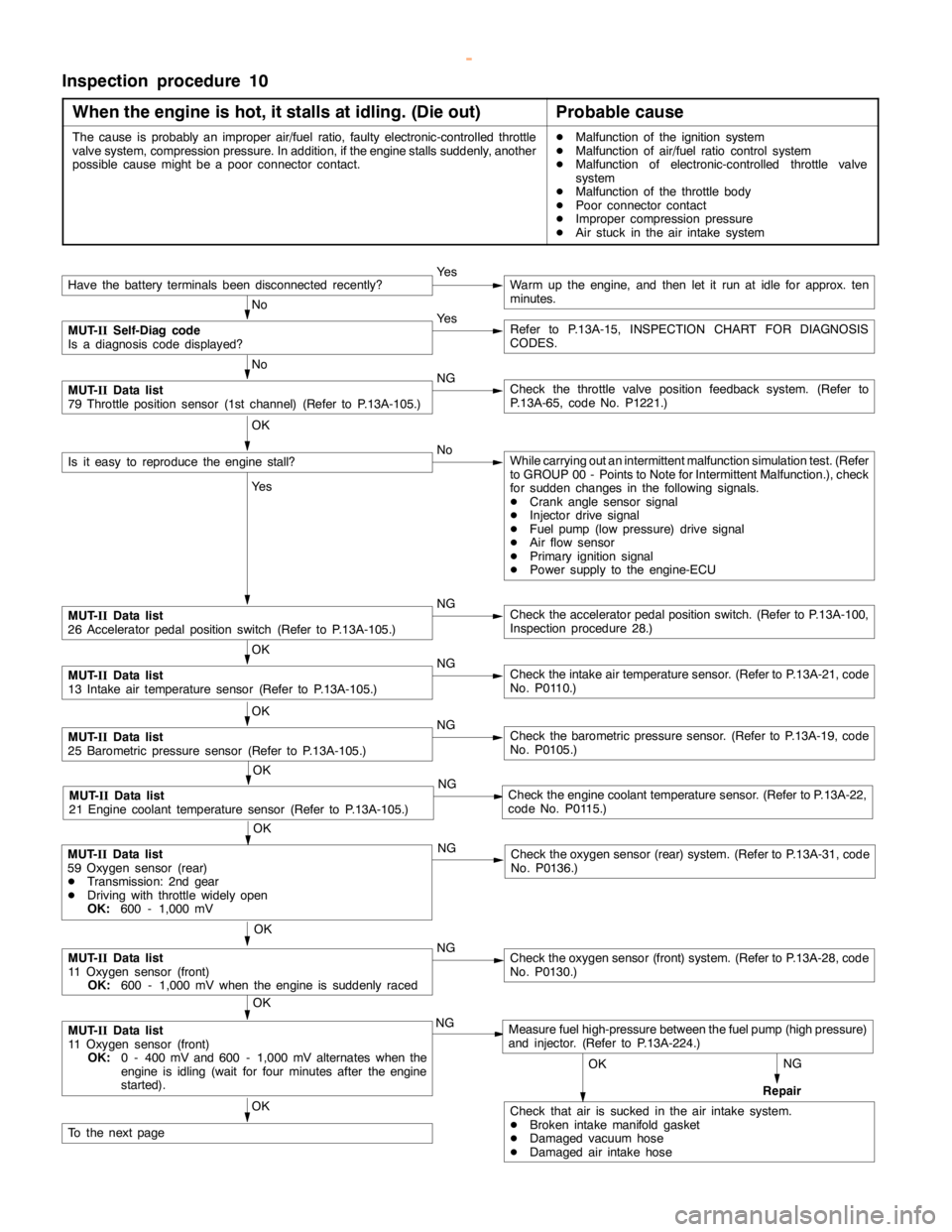
Inspection procedure 10
When the engine is hot, it stalls at idling. (Die out)
Probable cause
The cause is probably an improper air/fuel ratio, faulty electronic-controlled throttle
valve system, compression pressure. In addition, if theenginestalls suddenly, another
possible causemight be a poorconnector contact.DMalfunction of the ignition system
DMalfunction of air/fuel ratio control system
DMalfunction of electronic-controlled throttle valve
system
DMalfunction of the throttle body
DPoor connector contact
DImproper compression pressure
DAir stuck in the air intake system
NG
Repair
Have the battery terminalsbeen disconnectedrecently?Ye sWarm up the engine, and then let it run at idle for approx. ten
minutes.
No
MUT-
IISelf-Diag code
Is a diagnosis code displayed?Ye sRefer to P.13A-15, INSPECTION CHART FOR DIAGNOSIS
CODES.
No
MUT-
IIData list
79 Throttle position sensor (1st channel) (Refer to P.13A-105.)NGCheck the throttle valve position feedback system. (Refer to
P.13A-65, code No. P1221.)
OK
Is it easy to reproduce theengine stall?NoWhile carrying out an intermittent malfunction simulation test. (Refer
to GROUP 00 - Points to Note for Intermittent Malfunction.), check
for sudden changes in the following signals.
DCrankanglesensor signal
DInjector drive signal
DFuel pump(low pressure) drive signal
DAir flow sensor
DPrimary ignition signal
DPower supply to the engine-ECU
Ye s
MUT-
IIData list
26 Acceleratorpedal positionswitch (Refer to P.13A-105.)NGCheck the acceleratorpedal positionswitch. (Refer to P.13A-100,
Inspection procedure 28.)
OK
MUT-
IIData list
13 Intake air temperature sensor (Refer to P.13A-105.)NGCheck the intake air temperature sensor. (Refer to P.13A-21, code
No. P0110.)
OK
MUT-
IIData list
25 Barometric pressure sensor (Refer to P.13A-105.)NGCheck the barometric pressure sensor. (Refer to P.13A-19, code
No. P0105.)
OK
MUT-
IIData list
21 Engine coolant temperature sensor (Refer to P.13A-105.)NGCheck theengine coolant temperaturesensor. (Refer to P.13A-22,
code No. P0115.)
OK
MUT-
IIData list
11 Oxygen sensor (front)
OK:
600 - 1,000 mV when theengine is suddenlyracedNGCheck the oxygen sensor (front) system. (Refer to P.13A-28, code
No. P0130.)
OK
MUT-
IIData list
11 Oxygen sensor (front)
OK:
0 - 400 mV and 600 - 1,000 mV alternates when the
engine is idling(wait for four minutes after theengine
started).NGMeasure fuel high-pressure between the fuel pump (highpressure)
and injector. (Refer to P.13A-224.)
OK
Check that air is sucked in the air intake system.
DBroken intakemanifoldgasket
DDamaged vacuum hose
DDamaged air intake hoseOK
To the nextpage
OK
MUT-
IIData list
59 Oxygen sensor (rear)
DTransmission: 2nd gear
DDriving with throttle widelyopen
OK:
600 - 1,000 mVNGCheck the oxygen sensor (rear) system. (Refer to P.13A-31, code
No. P0136.)
www.WorkshopManuals.co.uk
Purchased from www.WorkshopManuals.co.uk