2000 MITSUBISHI MONTERO coolant
[x] Cancel search: coolantPage 229 of 1839

GDI -Troubleshooting
INSPECTION CHART FOR DIAGNOSIS CODES
Code No.Diagnosis itemReference page
P0100Air flow sensor system13A-17
P0105Barometric pressure sensor system13A-19
P0110Intake air temperature sensor system13A-21
P0115Engine coolant temperature sensor system13A-22
P0120LThrottle position sensor (1st channel) system13A-25
P0125Feedback system13A-27
P0130Oxygen sensor (front) system
P0135Oxygen sensor heater (front) system
P0136Oxygen sensor (rear) system
P0141Oxygen sensor heater (rear) system
P0170Abnormal fuel system13A-34
P0190LAbnormal fuel pressure13A-36
P0201No.1 injector system13A-38
P0202No.2 injector system13A-40
P0203No.3 injector system13A-42
P0204No.4 injector system13A-44
P0205No.5 injector system13A-46
P0206No.6 injector system13A-48
P0220LAccelerator pedal position sensor (1st channel) system13A-50
P0225LThrottle position sensor (2nd channel) system13A-52
P0300LIgnition coil (power transistor) system13A-53
P0301No.1 cylinder misfire detected.13A-55
P0302No.2 cylinder misfire detected.13A-55
P0303No.3 cylinder misfire detected.13A-55
P0304No.4 cylinder misfire detected.13A-55
P0305No.5 cylinder misfire detected.13A-55
P0306No.6 cylinder misfire detected.13A-55
P0325Detonation sensor system13A-56
P0335Crank angle sensor system13A-56
P0340Camshaft position sensor system13A-58
P0403EGR valve system13A-60
P0420Catalyst malfunction13A-61
www.WorkshopManuals.co.uk
Purchased from www.WorkshopManuals.co.uk
Page 236 of 1839
GDI -Troubleshooting
OK
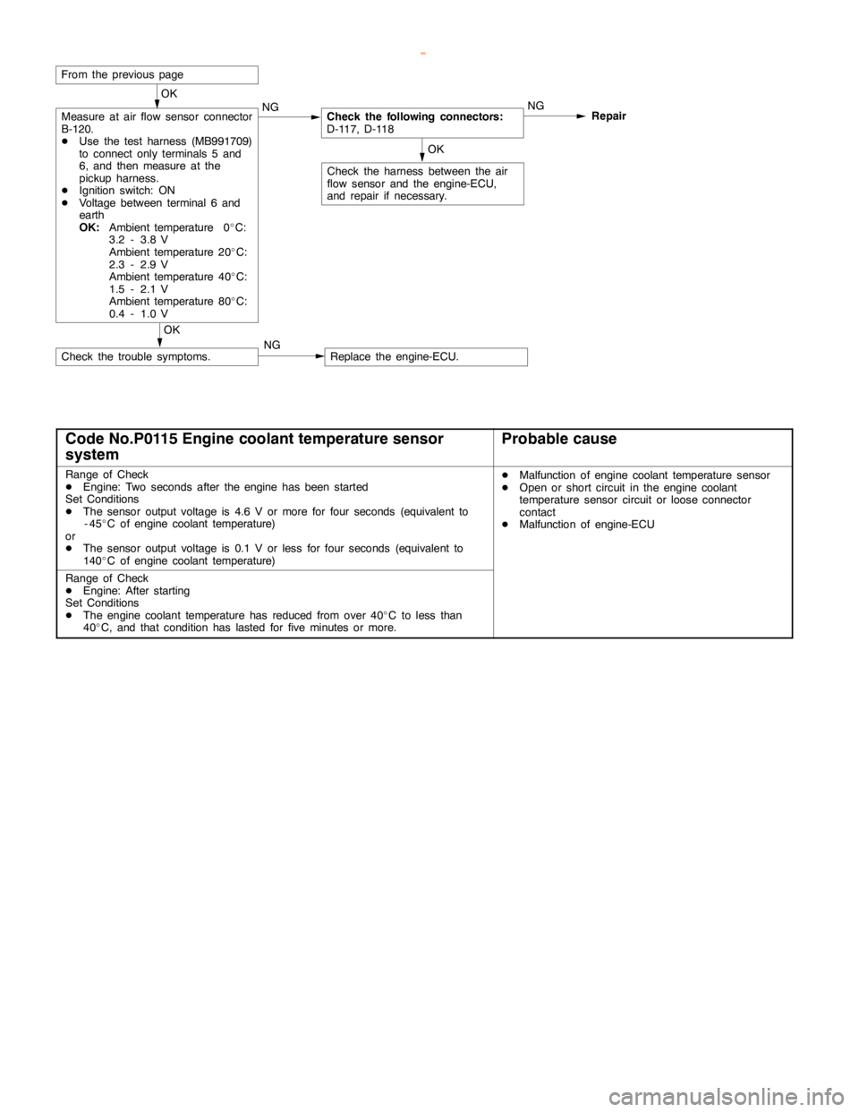
Measure at air flow sensor connector
B-120.
DUse the test harness (MB991709)
to connect only terminals 5 and
6, and then measure at the
pickup harness.
DIgnition switch: ON
DVoltage between terminal 6 and
earth
OK:
Ambient temperature 0_C:
3.2 - 3.8 V
Ambient temperature 20_C:
2.3 - 2.9 V
Ambient temperature 40_C:
1.5 - 2.1 V
Ambient temperature 80_C:
0.4 - 1.0 VNGCheck the following connectors:
D-117, D-118NG
Repair
OK
Check the harness between the air
flow sensor and the engine-ECU,
and repair if necessary.
OK
Check the trouble symptoms.NGReplace the engine-ECU.
From the previouspage
Code No.P0115 Engine coolant temperature sensor
systemProbable cause
Range of Check
DEngine: Two seconds after theengine has beenstarted
Set Conditions
DThe sensor output voltage is 4.6 V or more for four seconds (equivalent to
-45_C of engine coolant temperature)
or
DThe sensor output voltage is 0.1 V or less for four seconds (equivalent to
140_C of engine coolant temperature)DMalfunction of engine coolant temperaturesensor
DOpen or short circuit in theengine coolant
temperature sensor circuit or loose connector
contact
DMalfunction of engine-ECU
Range of Check
DEngine: After starting
Set Conditions
DThe engine coolant temperature has reduced fromover 40_C to less than
40_C, and that condition has lasted for five minutes or more.
www.WorkshopManuals.co.uk
Purchased from www.WorkshopManuals.co.uk
Page 237 of 1839
GDI -Troubleshooting
OK
Check the harness wire between the
engine coolant temperaturesensor
and the engine-ECU, and repair if
necesary.
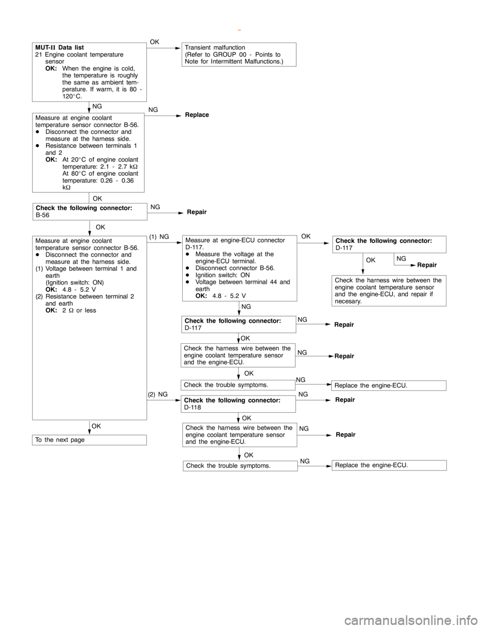
MUT-
IIData list
21 Engine coolant temperature
sensor
OK:
When the engine iscold,
the temperature is roughly
the same asambient tem-
perature. If warm, it is 80 -
120_C.OKTransient malfunction
(Refer to GROUP 00 - Points to
Note for Intermittent Malfunctions.)
NG
NG
Replace
OK
Measure at engine coolant
temperature sensor connector B-56.
DDisconnect the connector and
measure at the harness side.
(1) Voltage between terminal 1 and
earth
(Ignition switch: ON)
OK:
4.8 - 5.2 V
(2) Resistance between terminal 2
and earth
OK:
2Wor less(1) NGMeasure at engine-ECU connector
D-117.
DMeasure the voltage at the
engine-ECU terminal.
DDisconnect connector B-56.
DIgnition switch: ON
DVoltage between terminal 44 and
earth
OK:
4.8 - 5.2 VOKCheck the following connector:
D-117
NG
Repair
NG
NG
Repair
OK
Check the trouble symptoms.NGReplace the engine-ECU.
OK
Check the following connector:
B-56NG
Repair
(2) NG
OKRepair
OK
Check the harness wire between the
engine coolant temperaturesensor
and the engine-ECU.NG
Repair
NG
Check the harness wire between the
engine coolant temperaturesensor
and the engine-ECU.NG
Repair
OK
Check the trouble symptoms.NGReplace the engine-ECU.
OK
To the nextpage
Measure at engine coolant
temperature sensor connector B-56.
DDisconnect the connector and
measure at the harness side.
DResistance between terminals 1
and 2
OK:
At 20_C of engine coolant
temperature: 2.1 - 2.7 kW
At 80_C of engine coolant
temperature: 0.26 - 0.36
kW
Check the following connector:
D-117
Check the following connector:
D-118
www.WorkshopManuals.co.uk
Purchased from www.WorkshopManuals.co.uk
Page 238 of 1839
GDI -Troubleshooting
OK
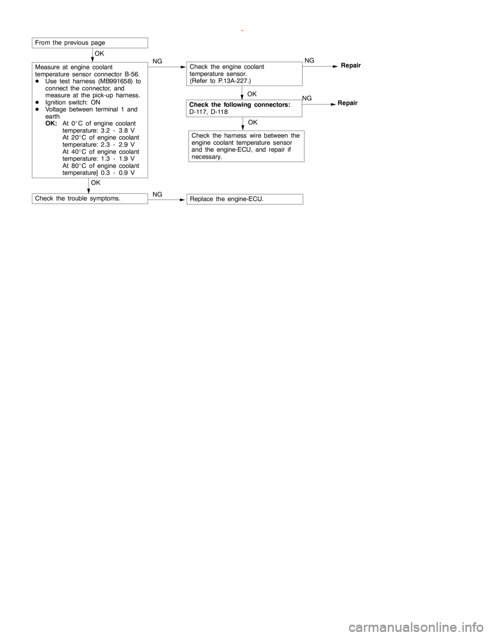
Measure at engine coolant
temperature sensor connector B-56.
DUse test harness (MB991658) to
connect the connector, and
measure at the pick-up harness.
DIgnition switch: ON
DVoltage between terminal 1 and
earth
OK:
At 0_C of engine coolant
temperature: 3.2 - 3.8 V
At 20_C of engine coolant
temperature: 2.3 - 2.9 V
At 40_C of engine coolant
temperature: 1.3 - 1.9 V
At 80_C of engine coolant
temperature] 0.3 - 0.9 VNGCheck theengine coolant
temperature sensor.
(Refer to P.13A-227.)NG
Repair
OK
Check the harness wire between the
engine coolant temperaturesensor
and the engine-ECU, and repair if
necessary.
OK
Check the trouble symptoms.NGReplace the engine-ECU.
OK
Check the following connectors:
D-117, D-118NG
Repair
From the previouspage
www.WorkshopManuals.co.uk
Purchased from www.WorkshopManuals.co.uk
Page 241 of 1839
GDI -Troubleshooting
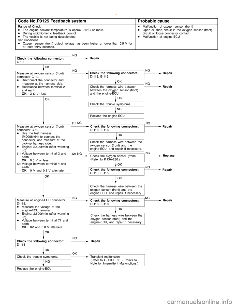
Code No.P0125 Feedback systemProbable cause
Range of Check
DThe engine coolant temperature is approx. 80_C or more.
DDuring stoichiometric feedback control
DThe vechile is notbeing deccelerated.
Set Conditions
DOxygen sensor (front) output voltage hasbeen higher orlower than 0.5 V for
at least thirty seconds.DMalfunction of oxygen sensor (front)
DOpen or short circuit in the oxygen sensor (front)
circuit or loose connector contact
DMalfunction of engine-ECU
Repair
OK
Measure at oxygen sensor (front)
connector C-19.
DDisconnect the connector and
measure at the harness side.
DResistance between terminal 2
and earth
OK:
2Wor lessNGCheck the following connectors:
D-118, E-116NG
OK
Check the trouble symptoms.
Check the following connector:
C-19NG
Repair
(2) NGCheck the oxygen sensor (front).
(Refer to P.13A-230.)NGReplace
OK
Check the harness wire between
between the oxygen sensor (front)
and the engine-ECU.NG
Repair
NG
Replace the engine-ECU.
Repair
OK
Measure at oxygen sensor (front)
connector C-19.
DUse the test harness
(MD998464) to connect the
connector, and measure at the
pick-up harness side.
DEngine: 2,500r/min (after warming
up)
(1) Voltage between terminal 2 and
earth
OK:
0.5 V or less
(2) Voltage between terminal 4 and
earth
OK:
0 V and 0.8 V alternate.(1) NGCheck the following connectors:
D-118, E-116NG
OK
Check the harness wire between the
oxygen sensor (front) and the
engine-ECU, and repair if necessary.
OK
NG
Repair
OK
Check the harness wire between the
oxygen sensor (front) and the
engine-ECU, and repair if necessary.
OK
NG
Check the following connectors:
D-118, E-116NG
OK
Check the harness wire between the
oxygen sensor (front) and the
engine-ECU, and repair if necessary.
OK
Check the following connector:
D-118
OKRepairNG
Check the trouble symptoms.OKTransient malfunction
(Refer to GROUP 00 - Points to
Note for Intermittent Malfunctions.)
NG
Replace the engine-ECU.
Repair
Check the following connectors:
D-118, E-116
Measure at engine-ECU connector
D-118.
DMeasure the voltage at the
engine-ECU terminal.
DEngine: 2,500r/min (after warming
up)
DVoltage between terminal 71 and
earth
OK:
0V and 0.8 V alternate.
www.WorkshopManuals.co.uk
Purchased from www.WorkshopManuals.co.uk
Page 242 of 1839

GDI -Troubleshooting
Code No.P0130 Oxygen sensor (front) system
Range of Check
DThree minutes havebeenpassed since theengine has been started.
DThe engine coolant temperature is approx. 80_C or more.
DIntake air temperature is 20 - 50_C
DEngine speed is 1,200 r/min or more
DDriving on a level surface at constant speed.
Set Conditions
DThe oxygen sensor (front) output voltage is 4.5 V or more when the sensor
output voltage is 0.2 V or less and a voltage of 5 V isapplied to theoxygen
sensor (front) inside the engine-ECU.DMalfunction of oxygen sensor (front)
DOpen or short circuit in the oxygen sensor (front)
circuit or loose connector contact
DMalfunction of engine-ECU
Range of Check
DEngine speed is 3,000 r/min or less
DDuring driving
DDuring air/fuel ratio feedback control
Set Conditions
DThe oxygen sensor (front) output frequency is five or less per 12 seconds on
average.
www.WorkshopManuals.co.uk
Purchased from www.WorkshopManuals.co.uk
Page 244 of 1839
GDI -Troubleshooting
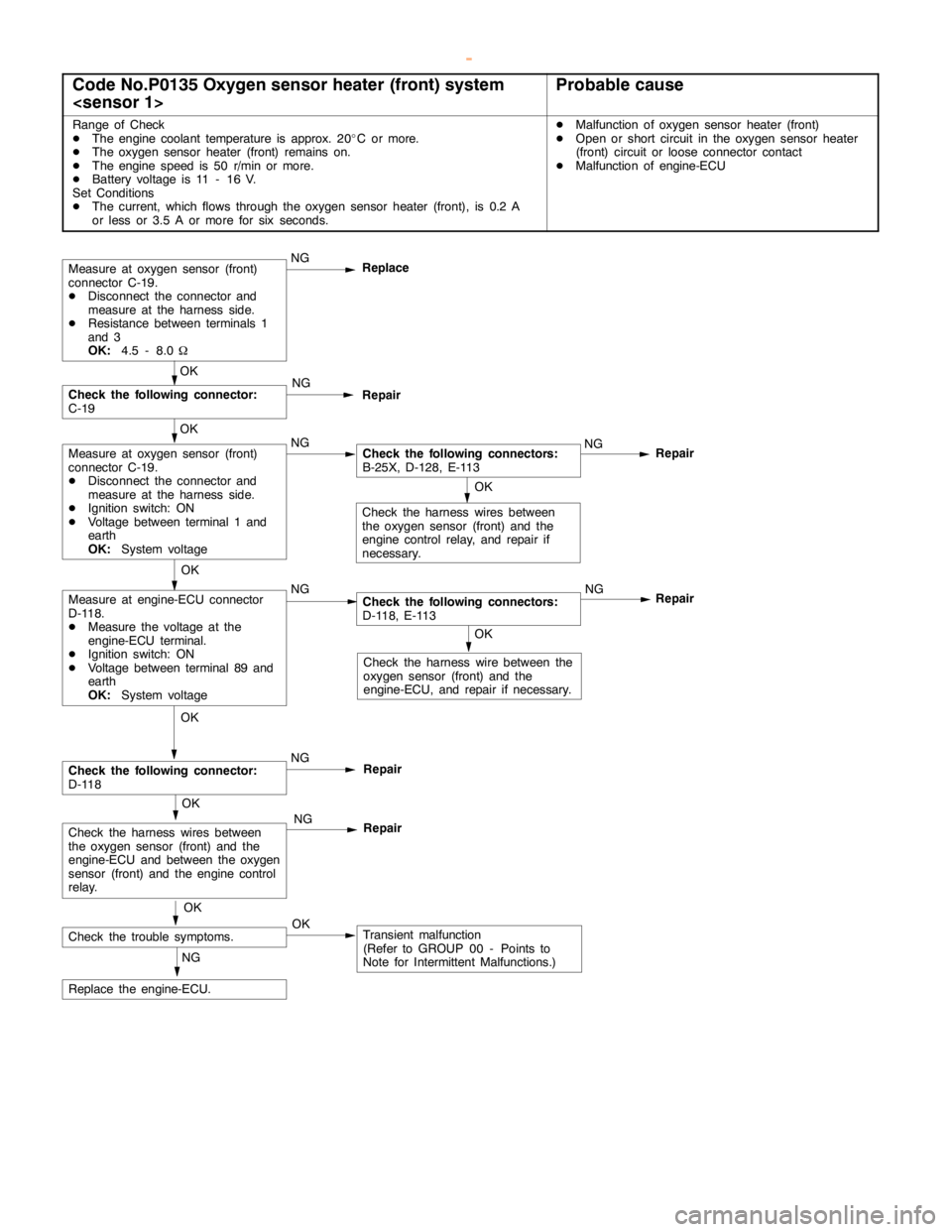
Code No.P0135 Oxygen sensor heater (front) system
Range of Check
DThe engine coolant temperature is approx. 20_C or more.
DThe oxygen sensor heater (front) remains on.
DThe enginespeed is 50 r/min or more.
DBattery voltage is 11 - 16 V.
Set Conditions
DThe current, which flows through the oxygen sensor heater (front), is 0.2 A
or less or 3.5 A or more for six seconds.DMalfunction of oxygen sensor heater (front)
DOpen or short circuit in the oxygen sensor heater
(front) circuit or loose connector contact
DMalfunction of engine-ECU
OK
Check the harness wire between the
oxygen sensor (front) and the
engine-ECU, and repair if necessary.
Repair
OK
Measure at engine-ECU connector
D-118.
DMeasure the voltage at the
engine-ECU terminal.
DIgnition switch: ON
DVoltage between terminal 89 and
earth
OK:
System voltageNGCheck the following connectors:
D-118, E-113NG
OK
Check the harness wires between
the oxygen sensor (front) and the
engine controlrelay, and repair if
necessary.
Measure at oxygen sensor (front)
connector C-19.
DDisconnect the connector and
measure at the harness side.
DResistance between terminals 1
and 3
OK:
4.5 - 8.0WNG
Replace
Repair
OK
Measure at oxygen sensor (front)
connector C-19.
DDisconnect the connector and
measure at the harness side.
DIgnition switch: ON
DVoltage between terminal 1 and
earth
OK:
System voltageNGCheck the following connectors:
B-25X, D-128, E-113NG
OK
Check the following connector:
C-19NG
Repair
OK
Check the trouble symptoms.OKTransient malfunction
(Refer to GROUP 00 - Points to
Note for Intermittent Malfunctions.) NG
Replace the engine-ECU.
OK
Check the following connector:
D-118NG
Repair
OK
Check the harness wires between
the oxygen sensor (front) and the
engine-ECU and between the oxygen
sensor (front) and theengine control
relay.NG
Repair
www.WorkshopManuals.co.uk
Purchased from www.WorkshopManuals.co.uk
Page 245 of 1839

GDI -Troubleshooting
Code No.P0136 Oxygen sensor (rear) system
Range of Check
DThree minutes havebeenpassed since theengine has been started.
DThe engine coolant temperature is approx. 80_C or more.
DIntake air temperature is 20 - 50_C
DEngine speed is 1,200 r/min or more
DDriving on a level surface at constant speed.
Set Conditions
DThe oxygen sensor (rear) output voltage is 4.5 V or more when the sensor
output voltage is 0.2 V or less and a voltage of 5 V isapplied to theoxygen
sensor (rear) inside the engine-ECU.DMalfunction of oxygen sensor (rear)
DOpen or short circuit in the oxygen sensor (rear)
circuit or loose connector contact
DMalfunction of engine-ECU
Range of Check
DTwo seconds have passed after the ECU detected anopencircuit.
DWhen the oxygen sensor (front) is ingood condition.
Set Conditions
DWhen the air/fuel ratio is rich, the oxygen sensor (front) output voltage is 0.5
V or more, the oxygen sensor (rear) output voltage is less than 0.1 V, and
the oxygen sensor (rear) output voltage fluctuates within 0.078 V.
www.WorkshopManuals.co.uk
Purchased from www.WorkshopManuals.co.uk