2000 MITSUBISHI MONTERO ECU
[x] Cancel search: ECUPage 529 of 1839

DIESEL FUEL <4M4> -Troubleshooting13C-38
Item
No.Reference
page Code No.
or inspec-
tion proce-
dure No. Value to be determined
as normal Inspection
conditions Drive Con-
tents Check item
25GE actuatorTurn the GE
actuator to
ONDIgnition
switch: ON
DEngine
speed:
0 r/min orMakes an audible
soundCode
No.4813C-21
26Turn the GE
actuator to
OFF
0 r/min or
lower
DControl
sleeve posi-
tion sensor:
Normal
27Fuel cut solenoid
valveTurn the
solenoid
valve to ONDIgnition
switch: ON
DVehicle
speed:
0 km/hMakes an audible
sound––
28EGR solenoid
valve No.1Turn the
solenoid
valve to ONDIgnition
switch: ON
DVehicleMakes an audible
sound––
29Turn the
solenoid
valve to ONspeed:
0 km/h
30EGR solenoid
valve No.2Turn the
solenoid
valve from
OFF to ON or
from ON to
OFFDIgnition
switch: ON
DVehicle
speed:
0 km/hMakes an audible
sound––
33PTC heaterSwitch the
PTC heater
relay ON/
OFF.DIgnition
switch: ONVoltage on the ECU
terminal No.9: 0 - 1V––
34Middle position
of GE actuatorHold the
injection
governor in
its middle
position.DIgnition
switch: ONWhen the crankshaft
is turned clockwise
during the adjustment
of the injection timing,
the injection pipes
spray out fuel.Code
No.4813C-21
www.WorkshopManuals.co.uk
Purchased from www.WorkshopManuals.co.uk
Page 533 of 1839

O
N-V EH IC LE SER VIC E
I N JE C TIO N TIM IN G CHEC K AND
A DJU STM EN T
R efe r to GRO UP 11 C -Engin e Adju stm ent.
I D LE SPEED CHEC K AND ADJU STM EN T
R efe r to GRO UP 11 C -Engin e Adju stm ent.
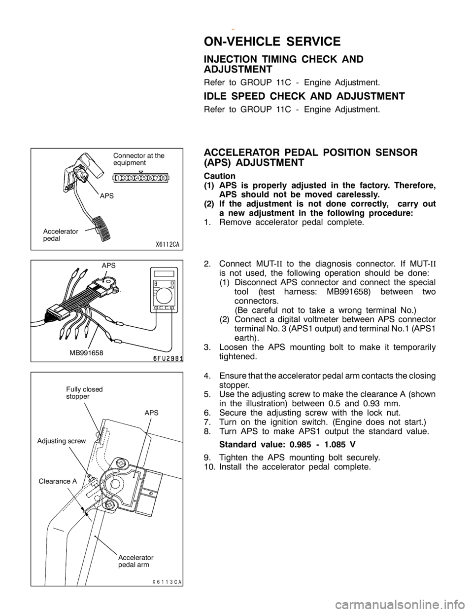
A CCELE R ATO R PED AL PO SIT IO N SEN SO R
( A PS) ADJU STM EN T
C au tio n
( 1 ) APS is pro perly ad ju ste d in th e fa cto ry . There fo re ,
A PS sh ould not be moved care le ssly .
( 2 ) If th e ad ju stm en t is not done co rre ctly , carry out
a new ad ju stm en t in th e fo llo w in g pro ced ure :
1 . Rem ove acce le ra to r pedal co m ple te .
2 . Connect M UT-I I to th e dia gnosis co nnecto r. If M UT-I I
i s not use d, th e fo llo w in g opera tio n sh ould be done:
( 1 ) Dis co nnect APS co nnecto r and co nnect th e sp ecia l
t o ol (te st harn ess: MB991658) betw een tw o
c o nnecto rs .
( B e ca re fu l not to ta ke a wro ng te rm in al N o.)
( 2 ) Connect a dig it a l vo lt m ete r betw een APS co nnecto r
t e rm in alN o.3 (A PS1 outp ut) a nd te rm in alN o.1 (A PS1
e arth ).
3 . Loose n th e APS mountin g bolt to make it te m pora rily
t ig hte ned.
4 . Ensu re th atth e acce le ra to rp edala rm co nta cts th e clo sin g
s to pper.
5 . Use th e adju stin g scre w to make th e cle ara nce A (s h ow n
i n th e illu str a tio n) betw een 0.5 and 0.9 3 mm.
6 . Secu re th e adju stin g scre w wit h th e lo ck nut.
7 . Turn on th e ig nit io n sw it c h . (E ngin e does not sta rt.)
8 . Turn APS to make APS1 outp ut th e sta ndard va lu e.
S ta n dard valu e: 0.9 85 -1.0 85 V
9 . Tig hte n th e APS mountin g bolt se cu re ly .
1 0. In sta ll th e acce le ra to r pedal co m ple te . C
onnecto r atth e
e quip m ent A
cce le ra to r
p edal A
PS M
B991658 A
cce le ra to r
p edala rm F
ully clo se d
s to pper A
dju stin g scre w A
PS C
le ara nce A w
ww.W ork sh opM an uals .c o .u k
P urc h ased f r o m w ww.W ork sh opM an uals .c o .u k
Page 557 of 1839

DIESEL FUEL <4M4> -General/Service Specifications/Troubleshooting13C-2
GENERAL
OUTLINE OF CHANGES
Some service procedures have been established as the following changes have been made due to the
compliance with the Emission Regulation StepIII.
DThe intake manifold cover and injection pump cover have been reshaped.
DThe throttle body assembly has been changed.
DThe EGR valve assembly has been changed.
SERVICE SPECIFICATIONS
ItemStandard value
Throttle body assembly resistanceΩat - 10 - 50_C12 - 20
at 50 - 100_C12 - 23
TROUBLESHOOTING
FAIL-SAFE, BACKUP FUNCTIONS
When abnormalities in the major sensors are detected by diagnosis functions, pre-set control logic operates
to maintain a safe driving condition for the vehicle.
Diagnosis itemControl features in malfunction
Accelerator pedal position sensorDAccelerator pedal released (idle switch ON)
Acceleration opening degree = 0 %
DAccelerator pedal applied (idle switch OFF)
Engine controlled at low speed
Acceleration opening degree = 40 %
DVoid cruise control
Idle switchDVoid idling speed control
DVoid cruise control
Engine speed sensorDEngine controlled at low speed
DVoid cruise control
Boost air temperature sensorMaintain the intake air temperature at 50_C
Vehicle speed sensorDVoid idling speed control
DVoid cruise control
DWith accelerator pedal released (when idle switch is on)
Accelerator opening angle = 0 %
DWith accelerator pedal depressed (when idle switch is off)
Accelerator opening angle = Fixed at 40 % (M/T), 28 % (A/T)
Engine coolant temperature sensorMaintain the engine coolant temperature at 80_C (engine running), 0_C
(engine stopped or just started)
Control sleeve position sensorDWith accelerator pedal released (when idle switch is on)
Engine speed = 800 r/min
DWith accelerator pedal depressed (when idle switch is off)
Engine speed = 2,000 r/min
DVoid cruise control
Timer piston position sensorDOpen control by means of engine speed
DVoid cruise control
Barometric pressure sensor (ECU built-in)Keep the barometric pressure at 101 kPa
www.WorkshopManuals.co.uk
Purchased from www.WorkshopManuals.co.uk
Page 559 of 1839

DIESEL FUEL <4M4> -Troubleshooting13C-4
INSPECTION PROCEDURE FOR DIAGNOSIS CODE
Code No. 11 Accelerator pedal position sensor systemProbable cause
Range of Check
DIgnition switch: ON, accelerator pedal position sensor (sub) operative, except
for during engine cranking
Set Conditions
DOutput voltage of accelerator pedal position sensor (sub) for one second is
0.2 V or higher and lower than 2.5 V and output voltage of accelerator pedal
position sensor (main) for one second is 4.5 V or higher, or lower than 0.2
V.
DOutput voltage of accelerator pedal position sensor (main) for 1 second is
lower than 0.2 V.
Range of Check
DIgnition switch: ON, except for during engine cranking
Set Conditions
DThe output voltage of accelerator pedal position sensor (main and sub) for
0.2 second is 0.2 V or higher, or lower than 4.5 V and the difference in
sensor output voltage between the main and sub for 0.2 second is 1 V or
higher.
DIdle switch: ON, and sensor main output voltage is 1.875 V or higher for 1
second.DAccelerator pedal position sensor inoperative
DAccelerator pedal position sensor open circuit,
short circuit, or connector contact inoperative
DEngine-ECU inoperative
Inspection procedures are the same as before.
Code No. 12 Boost pressure sensor (boost sensor)
system
Probable cause
Range of Check
DIgnition switch: ON, except for during engine cranking
Set Conditions
DSensor output voltage for one second is 4.5 V or higher (boost pressure is
approximately 306.7 kPa)
or
DSensor output voltage for one second is 0.2 V or lower (boost pressure is
approximately 13 kPa or lower)
Range of Check
DEngine speed is 1600 r/min or higher and the acceleration opening degree is
75%
Set Conditions
DBoost pressure is lower than the barometric pressure + 13 kPa for two
seconds.DBoost pressure sensor inoperative
DBoost pressure sensor open circuit, short circuit,
or connector contact inoperative
DBoost pressure sensor hose disconnected
DEngine-ECU inoperative
Inspection procedures are the same as before.
Code No. 13 Boost pressure sensor system
Probable cause
Range of Check
DIgnition switch: ON, except for during engine cranking
Set Conditions
DThe sensor output voltage is 4.5 V or higher for 3 seconds
or
DThe sensor output voltage is 1.5 V or lower for 3 secondsDEngine-ECU inoperative
Inspection procedures are the same as before.
Code No. 18 Engine speed sensor (backup) system
Probable cause
Range of Check
DIgnition switch: ON
DExcept for during engine stall and cranking
Set Conditions
DThe difference in the engine speed sensor output for 4 seconds: 325 r/min or
moreDEngine speed sensor inoperative
DEngine speed sensor open circuit, short circuit, or
connector contact inoperative
DEngine-ECU inoperative
Inspection procedures are the same as before.
www.WorkshopManuals.co.uk
Purchased from www.WorkshopManuals.co.uk
Page 560 of 1839

DIESEL FUEL <4M4> -TroubleshootingDIESEL FUEL <4M4> -Troubleshooting13C-5
Code No. 21 Engine speed sensor systemProbable cause
Range of Check
DDuring engine cranking
Set Conditions
DNo change in the engine speed sensor output voltage for 1 seconds (on
pulse signal has been input)
Range of Check
DIgnition switch: ON
DExcept for during engine stall and cranking
DEngine speed is more than or equal to 600 r/min
Set Conditions
DNo change in the engine speed sensor output 0.3 secondsDEngine speed sensor inoperative
DEngine speed sensor open circuit, short circuit, or
connector contact inoperative
DEngine-ECU inoperative
Inspection procedures are the same as before.
Code No. 23 Idle switch (accelerator pedal position sensor
built-in) system
Probable cause
Range of Check
Ignition switch: ON, accelerator pedal position sensor (main, sub) operative,
except for during engine cranking
Set Conditions
DIdle switch (built-in): ON, accelerator pedal position sensor (main, sub) output
voltage for 0.8 second 1.875 V or higher
DIdle switch (built-in): OFF, accelerator pedal position sensor (main, sub)
opening degrees less than 1 %DAccelerator pedal position sensor inoperative
DAccelerator pedal position sensor open circuit,
short circuit, or connector contact inoperative
DIdle switch “ON” inoperative
DIdle switch signal line short circuit
DEngine-ECU inoperative
Inspection procedures are the same as before.
Code No. 27 Accelerator pedal position sensor (sub)
system
Probable cause
Range of Check
DIgnition switch: ON, accelerator pedal position sensor (main) operative, except
for during engine cranking
Set Conditions
DOutput voltage of accelerator pedal position sensor (main) for 1 second is
0.2 V or higher and lower than 2.5 V. Output voltage of accelerator pedal
position sensor (sub) for 1 second is 4.5 V or higher.
DOutput voltage of accelerator pedal position sensor (sub) for 1 second is
lower than 0.2 V.
Range of Check
DIgnition switch: ON, except for during engine cranking
Set Conditions
DOutput voltage of accelerator pedal position sensor (main and sub) is 0.2 V
or higher or lower than 4.5 V.
DThe difference in the output sensor voltage between the main and the sub
sensor for 0.2 seconds is 1.0 V or more.DAccelerator pedal position sensor inoperative
DAccelerator pedal position sensor open circuit,
short circuit, or connector contact inoperative
DEngine-ECU inoperative
Inspection procedures are the same as before.
www.WorkshopManuals.co.uk
Purchased from www.WorkshopManuals.co.uk
Page 561 of 1839

DIESEL FUEL <4M4> -Troubleshooting13C-6
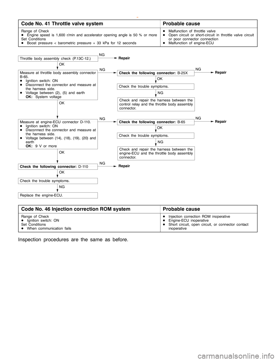
Code No. 41 Throttle valve systemProbable cause
Range of Check
DEngine speed is 1,600 r/min and accelerator opening angle is 50 % or more
Set Conditions
DBoost pressure < barometric pressure + 33 kPa for 12 secondsDMalfunction of throttle valve
DOpen circuit or short-circuit in throttle valve circuit
or poor connector connection
DMalfunction of engine-ECU
NG
Replace the engine-ECU.
OK
Check the trouble symptoms.
OK
NG
Check the following connector:D-110
OK
Check the trouble symptoms.
NG
Check and repair the harness between the
engine-ECU and the throttle body assembly
connector.
Repair NG
OK
Check the following connector:B-65 NG
OK
Check the trouble symptoms.
NG
Check and repair the harness between the
control relay and the throttle body assembly
connector.
Repair NG
OK
Check the following connector:B-25X NGMeasure at throttle body assembly connector
B-65.
DIgnition switch: ON
DDisconnect the connector and measure at
the harness side.
DVoltage between (2), (5) and earth
OK:System voltage
RepairThrottle body assembly check (P.13C-12.)NG
Measure at engine-ECU connector D-110.
DIgnition switch: ON
DDisconnect the connector and measure at
the harness side.
DVoltage between (14), (18), (19), (20) and
earth
OK:9 V or more
Repair
Code No. 46 Injection correction ROM systemProbable cause
Range of Check
DIgnition switch: ON
Set Conditions
DWhen communication failsDInjection correction ROM inoperative
DEngine-ECU inoperative
DShort circuit, open circuit, or connector contact
inoperative
Inspection procedures are the same as before.
www.WorkshopManuals.co.uk
Purchased from www.WorkshopManuals.co.uk
Page 562 of 1839

DIESEL FUEL <4M4> -Troubleshooting13C-7
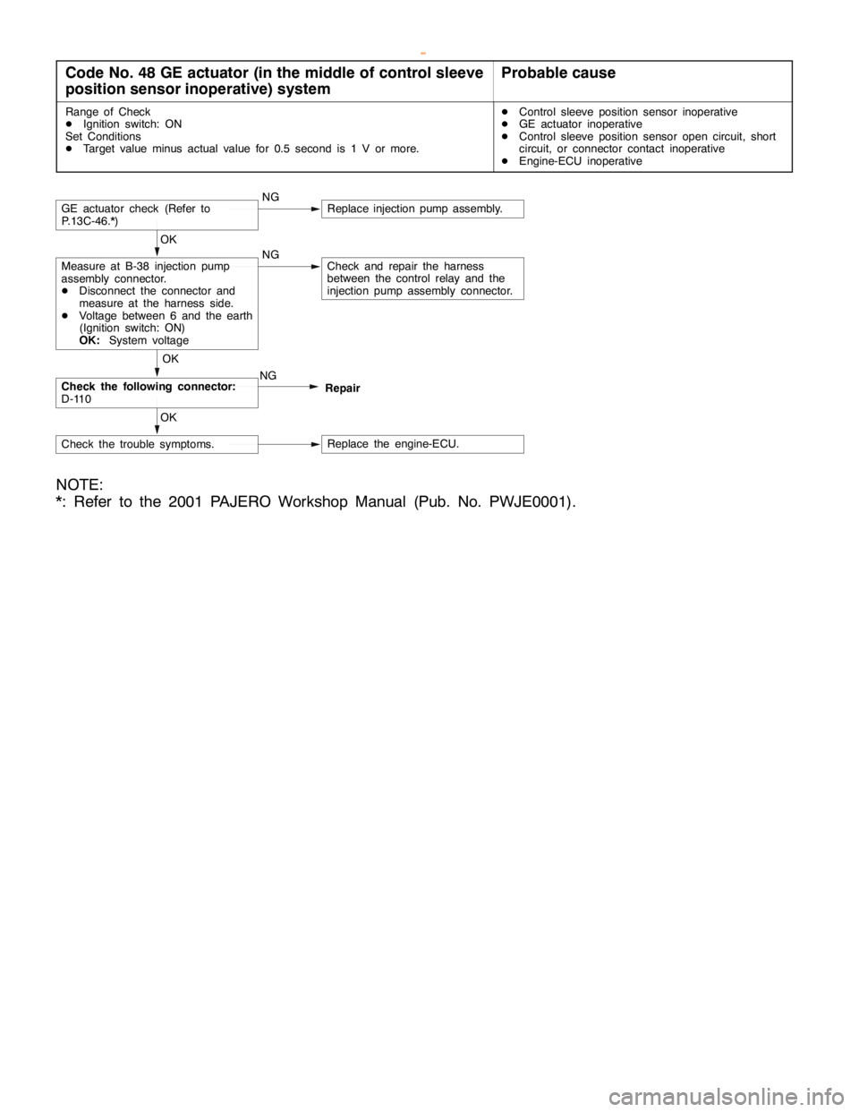
Code No. 48 GE actuator (in the middle of control sleeve
position sensor inoperative) systemProbable cause
Range of Check
DIgnition switch: ON
Set Conditions
DTarget value minus actual value for 0.5 second is 1 V or more.DControl sleeve position sensor inoperative
DGE actuator inoperative
DControl sleeve position sensor open circuit, short
circuit, or connector contact inoperative
DEngine-ECU inoperative
NGGE actuator check (Refer to
P.13C-46.*)Replace injection pump assembly.
NGMeasure at B-38 injection pump
assembly connector.
DDisconnect the connector and
measure at the harness side.
DVoltage between 6 and the earth
(Ignition switch: ON)
OK:System voltageCheck and repair the harness
between the control relay and the
injection pump assembly connector. OK
Check the following connector:
D-110NG OK
Repair
Check the trouble symptoms.Replace the engine-ECU. OK
NOTE:
*: Refer to the 2001 PAJERO Workshop Manual (Pub. No. PWJE0001).
www.WorkshopManuals.co.uk
Purchased from www.WorkshopManuals.co.uk
Page 563 of 1839

DIESEL FUEL <4M4> -Troubleshooting13C-8
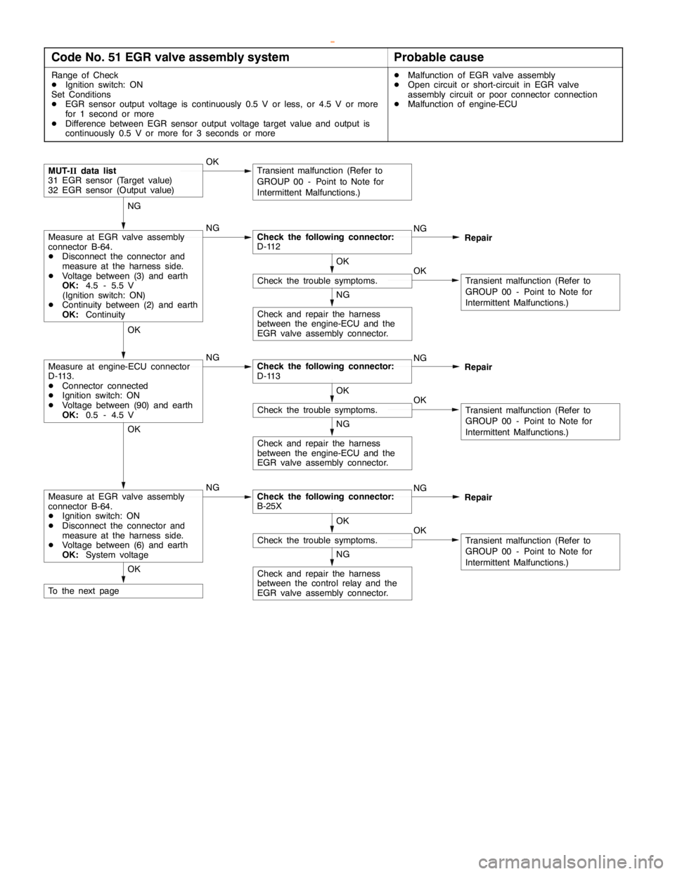
Code No. 51 EGR valve assembly systemProbable cause
Range of Check
DIgnition switch: ON
Set Conditions
DEGR sensor output voltage is continuously 0.5 V or less, or 4.5 V or more
for 1 second or more
DDifference between EGR sensor output voltage target value and output is
continuously 0.5 V or more for 3 seconds or moreDMalfunction of EGR valve assembly
DOpen circuit or short-circuit in EGR valve
assembly circuit or poor connector connection
DMalfunction of engine-ECU
Check and repair the harness
between the engine-ECU and the
EGR valve assembly connector.
NG
OKCheck the trouble symptoms.
OK
Transient malfunction (Refer to
GROUP 00 - Point to Note for
Intermittent Malfunctions.)
NGMeasure at engine-ECU connector
D-113.
DConnector connected
DIgnition switch: ON
DVoltage between (90) and earth
OK:0.5 - 4.5 VCheck the following connector:
D-113NG
Repair OK
Check and repair the harness
between the engine-ECU and the
EGR valve assembly connector.
NG
OKCheck the trouble symptoms.
OK
Transient malfunction (Refer to
GROUP 00 - Point to Note for
Intermittent Malfunctions.)
OKMUT-IIdata list
31 EGR sensor (Target value)
32 EGR sensor (Output value)Transient malfunction (Refer to
GROUP 00 - Point to Note for
Intermittent Malfunctions.)
NGMeasure at EGR valve assembly
connector B-64.
DDisconnect the connector and
measure at the harness side.
DVoltage between (3) and earth
OK:4.5 - 5.5 V
(Ignition switch: ON)
DContinuity between (2) and earth
OK:ContinuityCheck the following connector:
D-112NG
Repair NG
To the next pageOK
Check and repair the harness
between the control relay and the
EGR valve assembly connector.
NG
OKCheck the trouble symptoms.
OK
Transient malfunction (Refer to
GROUP 00 - Point to Note for
Intermittent Malfunctions.)
NGMeasure at EGR valve assembly
connector B-64.
DIgnition switch: ON
DDisconnect the connector and
measure at the harness side.
DVoltage between (6) and earth
OK:System voltageCheck the following connector:
B-25XNG
Repair OK
www.WorkshopManuals.co.uk
Purchased from www.WorkshopManuals.co.uk