2000 MITSUBISHI MONTERO ECU
[x] Cancel search: ECUPage 505 of 1839
DIESEL FUEL <4M4> -Troubleshooting13C-14
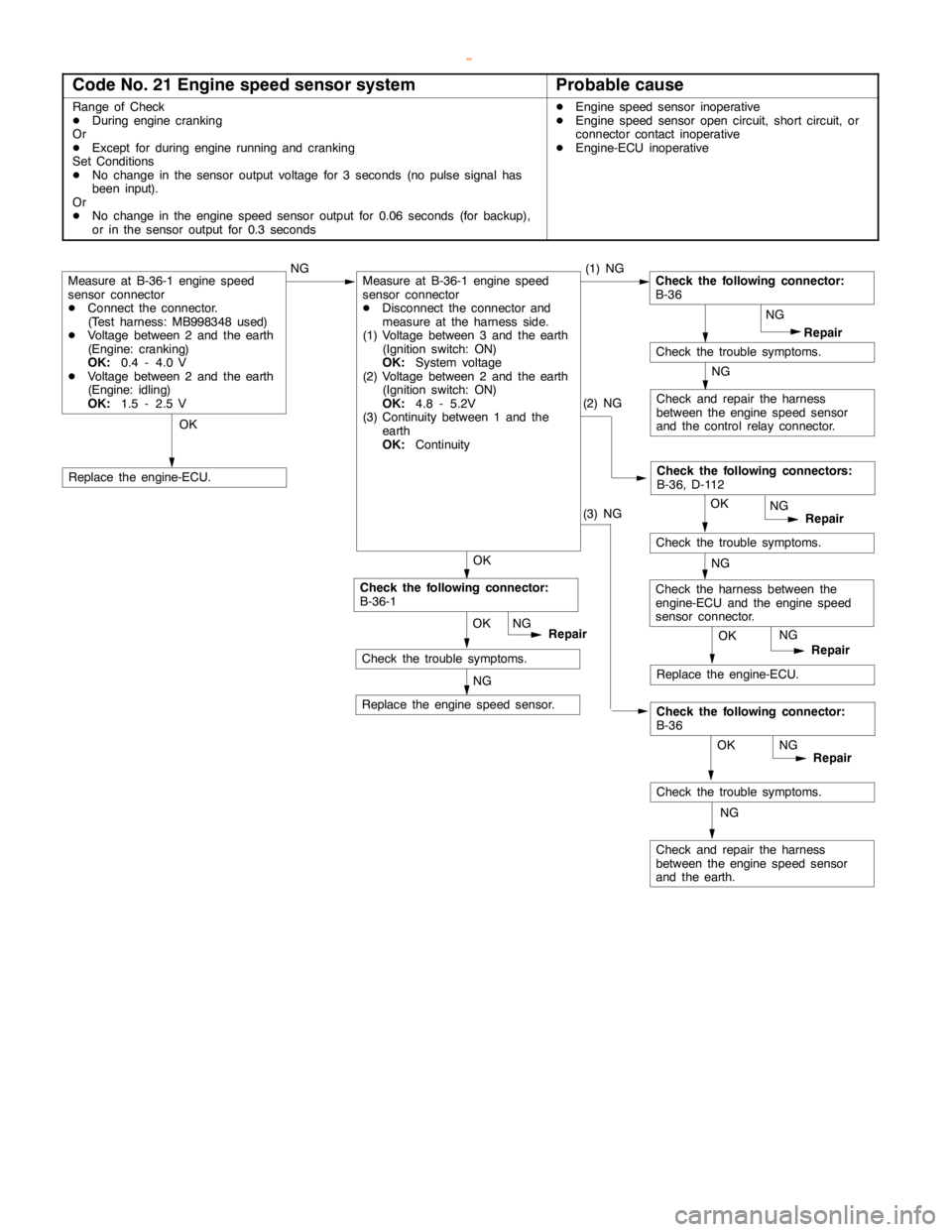
Code No. 21 Engine speed sensor systemProbable cause
Range of Check
DDuring enginecranking
Or
DExcept for duringengine running andcranking
Set Conditions
DNo change in the sensor output voltage for 3 seconds (no pulse signal has
been input).
Or
DNo change in the enginespeed sensor output for 0.06 seconds (for backup),
or in the sensor output for 0.3 secondsDEngine speed sensor inoperative
DEngine speed sensoropencircuit, short circuit, or
connector contact inoperative
DEngine-ECU inoperative
OK
Check and repair the harness
between the enginespeed sensor
and the control relay connector.OK
OK
NG
Repair
(1) NGMeasure at B-36-1 enginespeed
sensor connector
DConnect the connector.
(Test harness: MB998348 used)
DVoltage between 2 and the earth
(Engine: cranking)
OK:
0.4 - 4.0 V
DVoltage between 2 and the earth
(Engine: idling)
OK:
1.5 - 2.5 V
NG
Replace the enginespeed sensor.
Replace the engine-ECU.
Check the following connector:
B-36
NG
NG
Check the trouble symptoms.
OK
Repair
Check the following connectors:
B-36, D-112
NG
OK
Repair NG
Check the harness between the
engine-ECU and the enginespeed
sensor connector.NG
Check the trouble symptoms.
Replace the engine-ECU.
Check and repair the harness
between the enginespeed sensor
and the earth.OK
Repair
Check the following connector:
B-36
NG
NG
Check the trouble symptoms. OK
Repair NG
Check the following connector:
B-36-1
Check the trouble symptoms.
Measure at B-36-1 enginespeed
sensor connector
DDisconnect the connector and
measure at the harness side.
(1) Voltage between 3 and the earth
(Ignition switch: ON)
OK:
System voltage
(2) Voltage between 2 and the earth
(Ignition switch: ON)
OK:
4.8 - 5.2V
(3) Continuity between 1 and the
earth
OK:
Continuity(2) NG
(3) NG
www.WorkshopManuals.co.uk
Purchased from www.WorkshopManuals.co.uk
Page 506 of 1839
DIESEL FUEL <4M4> -Troubleshooting13C-15
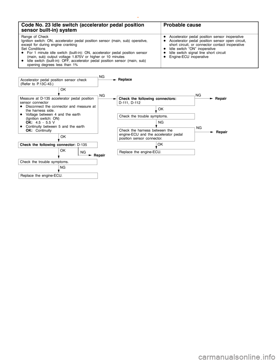
Code No. 23 Idle switch (accelerator pedal position
sensor built-in) systemProbable cause
Range of Check
Ignition switch: ON, acceleratorpedal positionsensor (main, sub) operative,
except for duringenginecranking
Set Conditions
DFor 1 minute idleswitch (built-in): ON, acceleratorpedal positionsensor
(main, sub) output voltage 1.875V or higher or 10 minutes
DIdle switch (built-in): OFF, acceleratorpedal positionsensor (main, sub)
opening degreesless than 1%DAcceleratorpedal positionsensor inoperative
DAcceleratorpedal positionsensoropencircuit,
short circuit, or connector contact inoperative
DIdle switch “ON” inoperative
DIdle switch signallineshort circuit
DEngine-ECU inoperative
OK
Measure at D-135 acceleratorpedal position
sensor connector
DDisconnect the connector and measure at
the harness side.
DVoltage between 4 and the earth
(Ignition switch: ON)
OK:
4.5 - 5.5 V
DContinuity between 5 and the earth
OK:
ContinuityNGCheck the following connectors:
D-111, D-112NG
Repair
OK
OKRepair
NGAcceleratorpedal positionsensor check
(Refer to P.13C-43.)
Check the trouble symptoms.
Replace the engine-ECU.NG
Replace the engine-ECU.OKNG
OK
Check the following connector:
D-135Replace
NG
Check the trouble symptoms.
Check the harness between the
engine-ECU and the accelerator pedal
position sensor connector.
NG
Repair
www.WorkshopManuals.co.uk
Purchased from www.WorkshopManuals.co.uk
Page 509 of 1839
DIESEL FUEL <4M4> -Troubleshooting13C-18
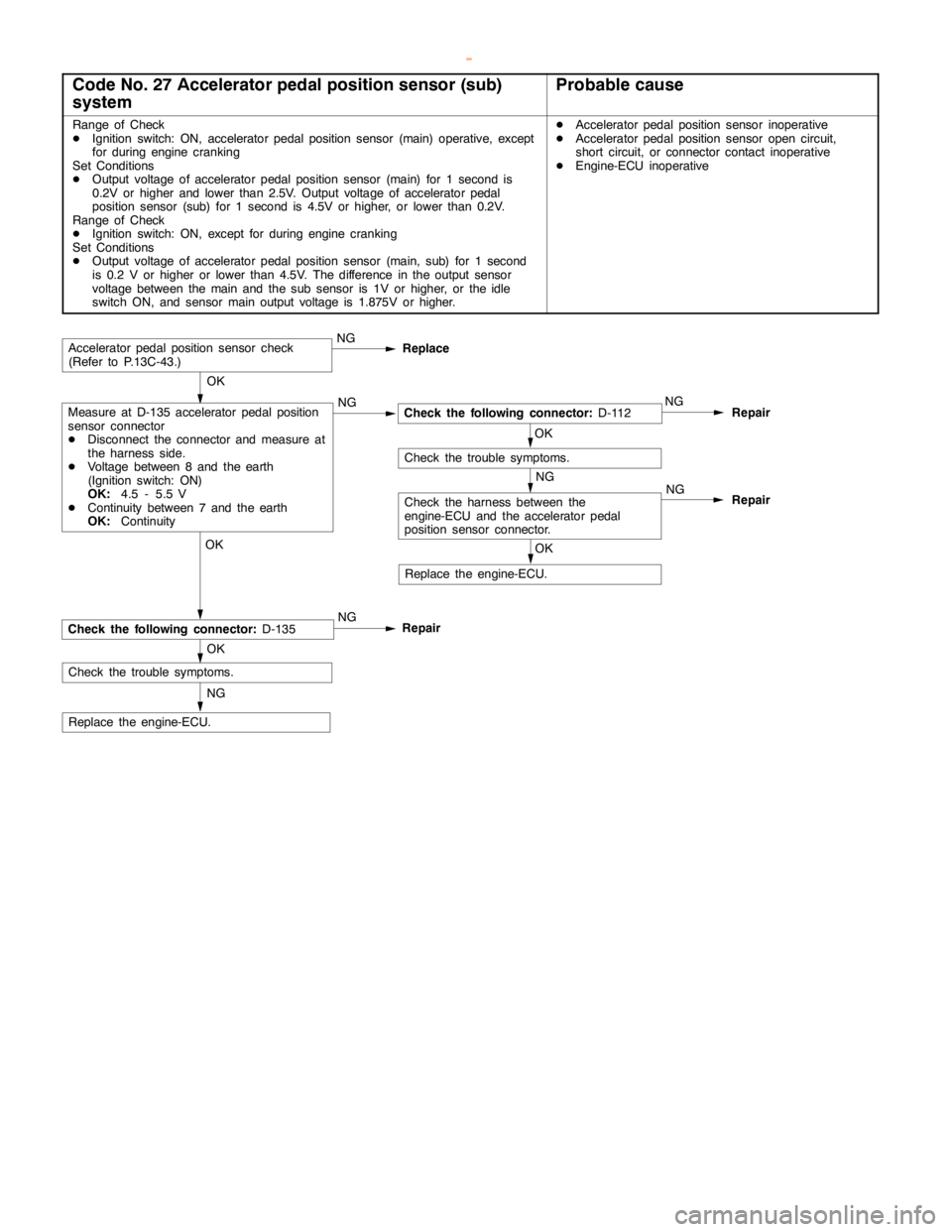
Code No. 27 Accelerator pedal position sensor (sub)
systemProbable cause
Range of Check
DIgnition switch: ON, acceleratorpedal positionsensor (main) operative, except
for during enginecranking
Set Conditions
DOutput voltage of accelerator pedal positionsensor (main) for 1 second is
0.2V or higher and lower than 2.5V. Output voltage of acceleratorpedal
position sensor (sub) for 1 second is 4.5V or higher, or lower than 0.2V.
Range of Check
DIgnition switch: ON, except for duringenginecranking
Set Conditions
DOutput voltage of accelerator pedal positionsensor (main, sub) for 1 second
is 0.2 V or higher or lower than 4.5V. The difference in the output sensor
voltage between the main and the subsensor is 1V or higher, or theidle
switch ON, and sensormain output voltage is 1.875V or higher.DAcceleratorpedal positionsensor inoperative
DAcceleratorpedal positionsensoropencircuit,
short circuit, or connector contact inoperative
DEngine-ECU inoperative
OK
Measure at D-135 acceleratorpedal position
sensor connector
DDisconnect the connector and measure at
the harness side.
DVoltage between 8 and the earth
(Ignition switch: ON)
OK:
4.5 - 5.5 V
DContinuity between 7 and the earth
OK:
ContinuityNGNG
Repair
OK
OKRepair
NGAcceleratorpedal positionsensor check
(Refer to P.13C-43.)
NG
Replace the engine-ECU.OKNG
OK
Replace
NG
Check the trouble symptoms.
NG
RepairCheck the following connector:
D-135
Check the harness between the
engine-ECU and the accelerator pedal
position sensor connector.
Check the trouble symptoms.
Replace the engine-ECU.
Check the following connector:
D-112
www.WorkshopManuals.co.uk
Purchased from www.WorkshopManuals.co.uk
Page 510 of 1839
DIESEL FUEL <4M4> -Troubleshooting13C-19
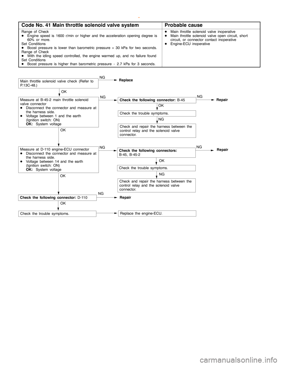
Code No. 41 Main throttle solenoid valve systemProbable cause
Range of Check
DEngine speed is 1600 r/min or higher and the accelerationopening degree is
60% or more.
Set Conditions
DBoost pressure is lower than barometric pressure + 30 kPa for two seconds.
Range of Check
DWith the idlingspeed controlled, theengine warmed up, and no failure found
Set Conditions
DBoost pressure is higher than barometric pressure - 2.7 kPa for 3 seconds.DMain throttle solenoidvalve inoperative
DMain throttle solenoidvalveopencircuit, short
circuit, or connector contact inoperative
DEngine-ECU inoperative
OK
Check the following connector:
B-45NG
Repair
OK
OK
Check and repair the harness between the
control relay and the solenoid valve
connector.
Main throttle solenoidvalve check (Refer to
P.13C-48.)
Check the trouble symptoms.
Replace the engine-ECU.
NG
OK
RepairCheck the following connector:
D-110
Check the trouble symptoms.NGReplace
NG NG
Check the following connectors:
B-45, B-45-2NG
Repair
OK
Check and repair the harness between the
control relay and the solenoid valve
connector.
Check the trouble symptoms.
NG
NGMeasure at D-110 engine-ECU connector
DDisconnect the connector and measure at
the harness side.
DVoltage between 14 and the earth
(Ignition switch: ON)
OK:
System voltageOK
Measure at B-45-2 main throttle solenoid
valve connector
DDisconnect the connector and measure at
the harness side.
DVoltage between 1 and the earth
(Ignition switch: ON)
OK:
System voltage
www.WorkshopManuals.co.uk
Purchased from www.WorkshopManuals.co.uk
Page 511 of 1839
DIESEL FUEL <4M4> -Troubleshooting13C-20
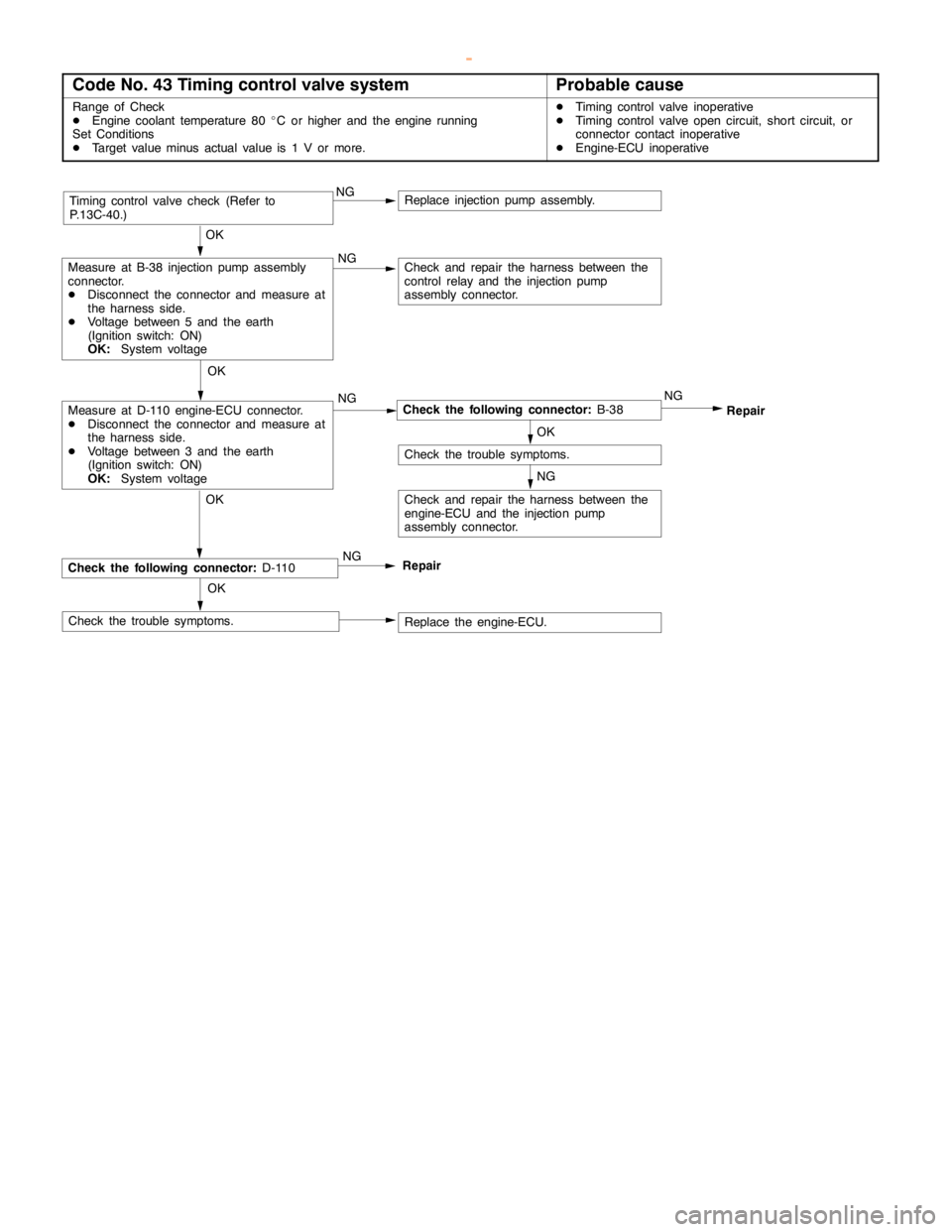
Code No. 43 Timing control valve systemProbable cause
Range of Check
DEngine coolant temperature 80_C or higher and the engine running
Set Conditions
DTarget value minus actual value is 1 V or more.DTiming controlvalve inoperative
DTiming controlvalveopencircuit, short circuit, or
connector contact inoperative
DEngine-ECU inoperative
OK
OK
Check and repair the harness between the
control relay and the injectionpump
assembly connector.
Timing controlvalve check (Refer to
P.13C-40.)
Replace the engine-ECU. OK
RepairCheck the following connector:
D-110
Check the trouble symptoms.NG NG NG
Check the following connector:
B-38NG
Repair
OK
Check the trouble symptoms.
NG
NGMeasure at D-110 engine-ECU connector.
DDisconnect the connector and measure at
the harness side.
DVoltage between 3 and the earth
(Ignition switch: ON)
OK:
System voltageOK
Measure at B-38 injectionpumpassembly
connector.
DDisconnect the connector and measure at
the harness side.
DVoltage between 5 and the earth
(Ignition switch: ON)
OK:
System voltage
Replace injection pumpassembly.
Check and repair the harness between the
engine-ECU and the injection pump
assembly connector.
www.WorkshopManuals.co.uk
Purchased from www.WorkshopManuals.co.uk
Page 512 of 1839
DIESEL FUEL <4M4> -Troubleshooting13C-21
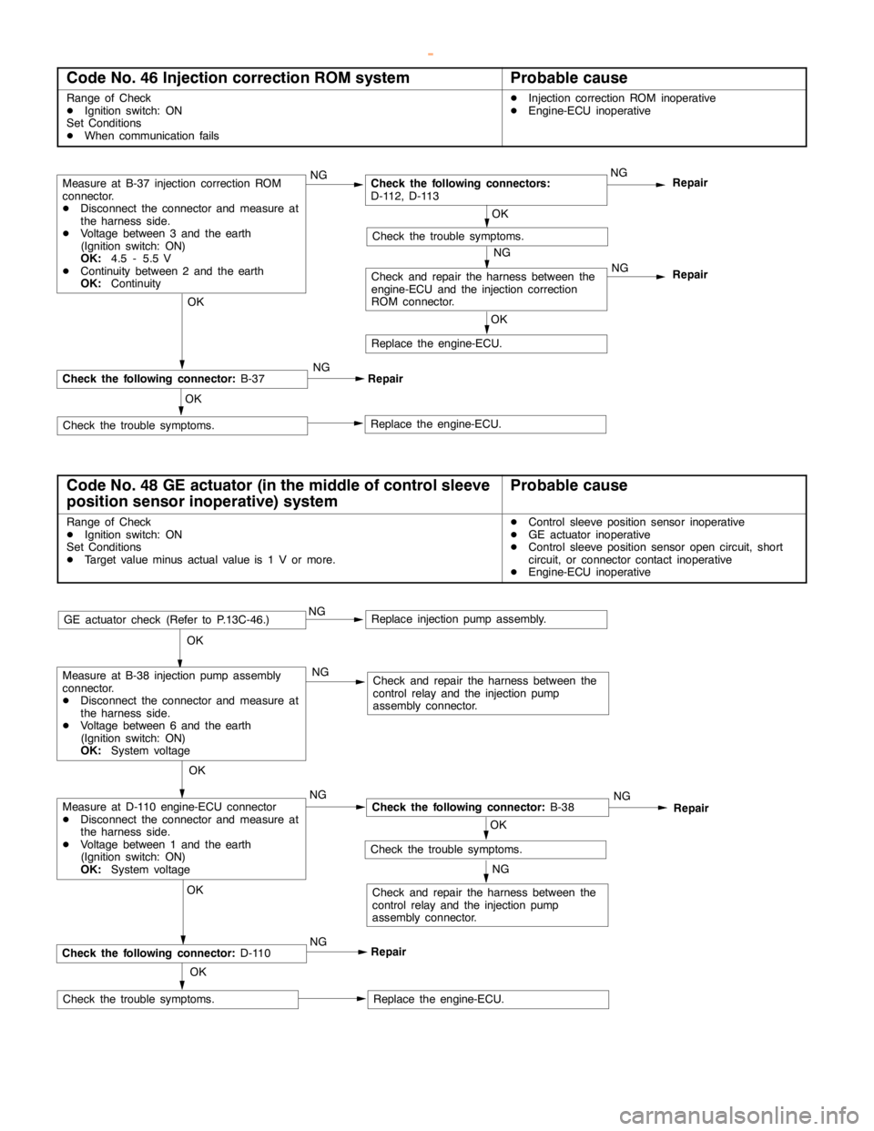
Code No. 46 Injection correction ROM systemProbable cause
Range of Check
DIgnition switch: ON
Set Conditions
DWhen communication failsDInjection correction ROM inoperative
DEngine-ECU inoperative
Repair
OK
Replace the engine-ECU. OK
RepairCheck the following connector:
B-37
Check the trouble symptoms.NG NG
Check the following connectors:
D-112, D-113
NG
Repair
OK
Check the trouble symptoms.
NG
Measure at B-37 injection correction ROM
connector.
DDisconnect the connector and measure at
the harness side.
DVoltage between 3 and the earth
(Ignition switch: ON)
OK:
4.5 - 5.5 V
DContinuity between 2 and the earth
OK:
Continuity
Check and repair the harness between the
engine-ECU and the injection correction
ROM connector.
OK
Replace the engine-ECU.NG
Code No. 48 GE actuator (in the middle of control sleeve
position sensor inoperative) systemProbable cause
Range of Check
DIgnition switch: ON
Set Conditions
DTarget value minus actual value is 1 V or more.DControl sleeve position sensor inoperative
DGE actuator inoperative
DControl sleeve position sensoropencircuit, short
circuit, or connector contact inoperative
DEngine-ECU inoperative
OK
OK
Check and repair the harness between the
control relay and the injectionpump
assembly connector.
GE actuator check (Refer to P.13C-46.)
Replace the engine-ECU. OK
RepairCheck the following connector:
D-110
Check the trouble symptoms.NGNG NG
Check the following connector:
B-38NG
Repair
OK
Check the trouble symptoms.
NG
NGMeasure at D-110 engine-ECU connector
DDisconnect the connector and measure at
the harness side.
DVoltage between 1 and the earth
(Ignition switch: ON)
OK:
System voltageOK
Measure at B-38 injectionpumpassembly
connector.
DDisconnect the connector and measure at
the harness side.
DVoltage between 6 and the earth
(Ignition switch: ON)
OK:
System voltage
Replace injection pumpassembly.
Check and repair the harness between the
control relay and the injectionpump
assembly connector.
www.WorkshopManuals.co.uk
Purchased from www.WorkshopManuals.co.uk
Page 513 of 1839
DIESEL FUEL <4M4> -TroubleshootingDIESEL FUEL <4M4> -Troubleshooting13C-22
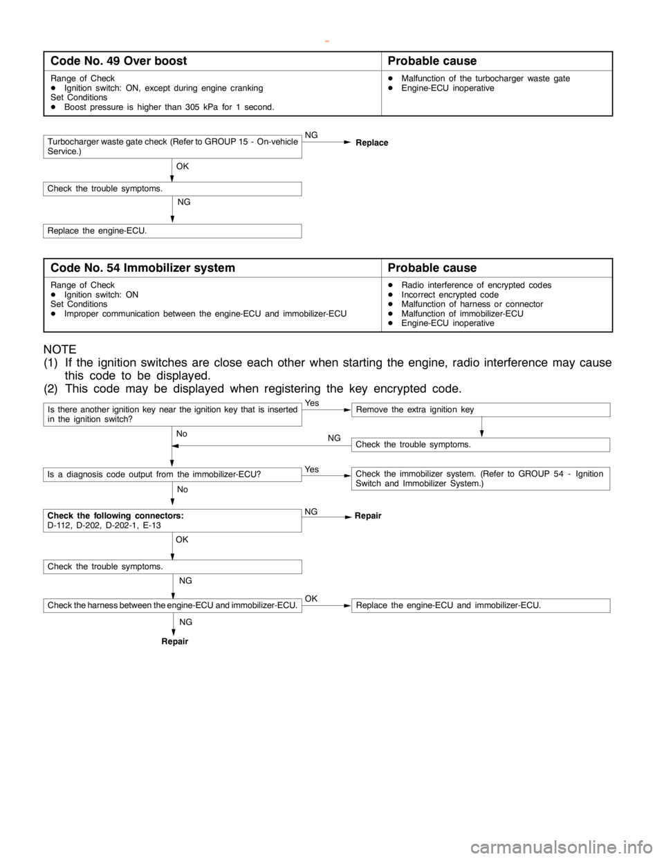
Code No. 49 Over boostProbable cause
Range of Check
DIgnition switch: ON, except duringenginecranking
Set Conditions
DBoost pressure is higher than 305 kPa for 1 second.DMalfunction of the turbocharger waste gate
DEngine-ECU inoperative
Turbocharger waste gate check (Refer to GROUP 15 - On-vehicle
Service.)NG
OK
Check the trouble symptoms.
NG
Replace the engine-ECU.Replace
Code No. 54 Immobilizer systemProbable cause
Range of Check
DIgnition switch: ON
Set Conditions
DImproper communication between the engine-ECU and immobilizer-ECUDRadio interference of encrypted codes
DIncorrect encrypted code
DMalfunction of harness or connector
DMalfunction of immobilizer-ECU
DEngine-ECU inoperative
NOTE
(1) If the ignition switches are close each other when starting the engine, radio interference may cause
this code to be displayed.
(2) This code may be displayed when registering the key encrypted code.
Is there another ignition key near the ignition key that is inserted
in the ignition switch?Ye sRemove the extra ignition key
No
Check the following connectors:
D-112, D-202, D-202-1, E-13NG
Repair
No
Is a diagnosis code output from the immobilizer-ECU?Ye sCheck the immobilizer system. (Refer to GROUP 54 - Ignition
Switch and Immobilizer System.)
NG OK
Check the trouble symptoms.
Check the harness between the engine-ECU and immobilizer-ECU.OKReplace the engine-ECU and immobilizer-ECU.
Check the trouble symptoms. NG
RepairNG
www.WorkshopManuals.co.uk
Purchased from www.WorkshopManuals.co.uk
Page 514 of 1839

DIESEL FUEL <4M4> -Troubleshooting13C-23
INSPECTION CHART FOR TROUBLE SYMPTOMS
Trouble SymptomInspection
procedure
No.Reference
page
No communication canNo communication can be established with all systems.113C-24
be established be-
tween MUT-IIand the
engine-ECU.No communication can be established only with the
engine-ECU.213C-24
Engine warning lamp
relatedImmediately after the ignition switch is “ON”, the engine
warning lamp does not turn on.313C-25
The engine warning lamp keeps on and does not turn off.413C-25
Starting performanceNo initial combustion (unable to start)513C-26
Starting performance is bad when the engine is cold (difficult to
start)613C-26
Starting performance is bad regardless of when the engine is
hot or cold (difficult to start)713C-26
Idling stability
(idling inoperative)Low idling speed when the engine is cold (improper idling
speed)813C-27
High idling speed (improper idling speed)913C-27
Low idling speed (improper idling speed)1013C-27
Idling instable (rough idling, hunting)1113C-28
Idling stabilityThe engine halts after running for a while.1213C-28
(idling sustainment in-
operative)The engine halts during idling.1313C-29
DriveabilityLack of output power1413C-29
Occurrence of abnormal knocking1513C-29
Abnormal black smoke1613C-30
Abnormal white smoke1713C-30
Hunting during driving1813C-31
www.WorkshopManuals.co.uk
Purchased from www.WorkshopManuals.co.uk