2000 MITSUBISHI MONTERO ECU
[x] Cancel search: ECUPage 564 of 1839
DIESEL FUEL <4M4> -Troubleshooting13C-9
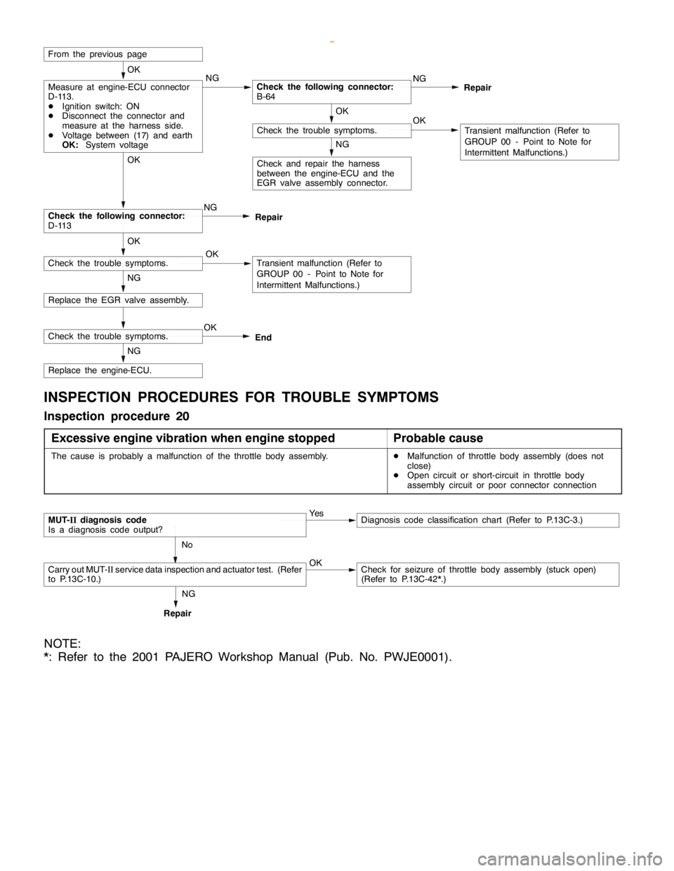
Replace the engine-ECU.
Replace the EGR valve assembly.NG
Check the following connector:
D-113NG OK
Check and repair the harness
between the engine-ECU and the
EGR valve assembly connector.
NG
OKCheck the trouble symptoms.
OK
Transient malfunction (Refer to
GROUP 00 - Point to Note for
Intermittent Malfunctions.)
From the previous page
NGMeasure at engine-ECU connector
D-113.
DIgnition switch: ON
DDisconnect the connector and
measure at the harness side.
DVoltage between (17) and earth
OK:System voltageCheck the following connector:
B-64NG
Repair OK
NG
OKCheck the trouble symptoms.Transient malfunction (Refer to
GROUP 00 - Point to Note for
Intermittent Malfunctions.) OKRepair
Check the trouble symptoms.OK
End
INSPECTION PROCEDURES FOR TROUBLE SYMPTOMS
Inspection procedure 20
Excessive engine vibration when engine stopped
Probable cause
The cause is probably a malfunction of the throttle body assembly.DMalfunction of throttle body assembly (does not
close)
DOpen circuit or short-circuit in throttle body
assembly circuit or poor connector connection
MUT-IIdiagnosis code
Is a diagnosis code output?Ye sDiagnosis code classification chart (Refer to P.13C-3.)
No
Carry out MUT-IIservice data inspection and actuator test. (Refer
to P.13C-10.)OKCheck for seizure of throttle body assembly (stuck open)
(Refer to P.13C-42*.)
RepairNG
NOTE:
*: Refer to the 2001 PAJERO Workshop Manual (Pub. No. PWJE0001).
www.WorkshopManuals.co.uk
Purchased from www.WorkshopManuals.co.uk
Page 566 of 1839

DIESEL FUEL <4M4> -Troubleshooting13C-11
ENGINE-ECU CHECK
TERMINAL VOLTAGE TABLE
Terminal No.Check itemInspection conditions (engine status)Normal condition
14Throttle body assembly (1)Ignition switch: ON (Engine stops)9 V or more
17EGR motorIgnition switch: ON (Engine stops)System voltage
18Throttle body assembly (2)Ignition switch: ON (Engine stops)9 V or more
19Throttle body assembly (3)Ignition switch: ON (Engine stops)9 V or more
20Throttle body assembly (4)Ignition switch: ON (Engine stops)9 V or more
33A/C load signalEngine: Idle
A/C switch: ONDuring weak cooling or
heatingSystem voltage
During normal cooling0-1V
During strong coolingChanges repeatedly
between 0 V and 12 V
37Clutch switch
Inhibitor switch Ignition switch:
ON (Engine stops)Move selector lever to N
or P0-1V
Move selector lever to D,
2, L or RSystem voltage
38Control relay (no immobi-
lizer)
Ignition switch: ON0-1V
lizer)
Ignition switch: ON→OFF (after approx. 8
seconds)System voltage
41Select switch
ON (Engine stops)Move shift lever to 4st or
RSystem voltage
421st - 2nd switch
ON (Engine stops)Move shift lever to 1st or
2ndSystem voltage
433rd - 4th switch
ON (Engine stops)Move shift lever to 3rd or
4thSystem voltage
445th - R switch
ON(Enginestops)
Move shift lever to 5th0-1V
ON(Engine stops)
Move shift lever to RSystem voltage
58TachometerDuring idlingChanges repeatedly
between 0 V and 12 V
90EGR valve sensorDuring racingChanges between 0.5
V and 4.5 V
www.WorkshopManuals.co.uk
Purchased from www.WorkshopManuals.co.uk
Page 590 of 1839

13E-1
MITSUBISHI STABILITY
CONTROL
(MITSUBISHI SC)
CONTENTS
GENERAL INFORMATION 2................
SERVICE SPECIFICATIONS 4..............
SPECIAL TOOLS 4........................
TROUBLESHOOTING 5....................
ON-VEHICLE SERVICE 18.................
Operation Test of MITSUBISHI SC 18.........Wheel Speed Sensor (FR) Check 18..........
Vehicle Speed Sensor Check 18..............
SC-ECU* 19...............................
G SENSOR 20.............................
WHEEL SPEED SENSOR (FR) 20..........
VEHICLE SPEED SENSOR 20..............
WARNINGS REGARDING SERVICING OF SUPPLEMENTAL RESTRAINT SYSTEM (SRS) EQUIPPED VEHICLES
WARNING!
(1) Improper service or maintenance of any component of the SRS, or any SRS-related component, can lead to personal
injury or death to service personnel (from inadvertent firing of the air bag) or to the driver and passenger (from rendering
the SRS inoperative).
(2) Service or maintenance of any SRS component or SRS-related component must be performed only at an authorized
MITSUBISHI dealer.
(3) MITSUBISHI dealer personnel must thoroughly review this manual, and especially its GROUP 52B - Supplemental
Restraint System (SRS) before beginning any service or maintenance of any component of the SRS or any SRS-related
component.
NOTE
The SRS includes the following components: front impact sensors, SRS-ECU, SRS warning lamp, air bag module, clock spring and
interconnecting wiring. Other SRS-related components (that may have to be removed/installed in connection with SRS service or
maintenance) are indicated in the table of contents by an asterisk (*).
www.WorkshopManuals.co.uk
Purchased from www.WorkshopManuals.co.uk
Page 595 of 1839

MITSUBISHI SC-Troubleshooting13E-6
INSPECTION CHART FOR DIAGNOSIS CODES
Diagnosis
code No.Diagnosis itemSC warning lampReference page
27*1SC-ECU power supply system (abnormal voltage drop)Flashes13E-6
51*2Vehicle speed sensor wheel speed sensor system (output
signal abnormality)Flashes13E-7
52Vehicle speed sensor system (open circuit or short-circuit)Flashes13E-8
53*2Wheel speed sensor system (open circuit or short-circuit)Flashes13E-8
55*2G sensor systemFlashes13E-9
71Communication line between the engine-ECU or engine-
A/T-ECU and the systemFlashes13E-10
72Engine-ECU or Engine-A/T-ECU systemIlluminates13E-10
74*2Communication line between the A/T-ECU and the system
<4M4-A/T>Flashes13E-11
81*1The SC - ECU is controlling the system too longFlashes13E-11
NOTE
*1: Code No.27 and 81 are erased from the memory if the condition returns to normal.
*2: For code Nos.51, 53, 55 and 74, a diagnosis code will be set in ten seconds after a failure is detected.
INSPECTION PROCEDURE FOR DIAGNOSIS CODE
Code No. 27 SC-ECU power supply system (abnormal
voltage drop)Probable cause
This diagnosis code will be set if the SC-ECU power supply voltage drops below
a certain level.DMalfunction of battery
DMalfunction of harness or connector
DMalfunction of the SC-ECU
Caution
If the system voltage drops during inspection, this code will be output to indicate a current problem.
And correct problem diagnosis will not be possible. Before carrying out the following procedure,
check the battery and recharge it if necessary.
www.WorkshopManuals.co.uk
Purchased from www.WorkshopManuals.co.uk
Page 596 of 1839
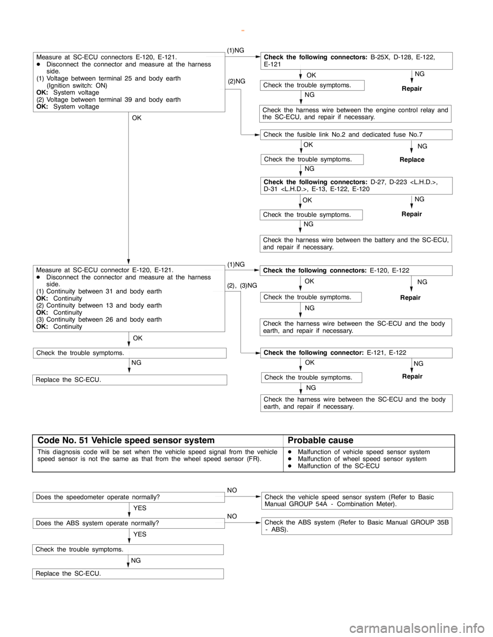
MITSUBISHI SC-Troubleshooting MITSUBISHI SC-Troubleshooting13E-7
OK
NG
Repair
OK
Check the trouble symptoms.
NG
OKNG
Repair
OK
(1)NGCheck the following connectors:
B-25X, D-128, E-122,
E-121
NG
Check the harness wire between the engine control relay and
the SC-ECU, and repair if necessary. (2)NG
OK
Check the trouble symptoms.
NG
Replace
NG
Check the harness wire between the battery and the SC-ECU,
and repair if necessary.
Check the following connectors:
D-27, D-223
D-31
Measure at SC-ECU connectors E-120, E-121.
DDisconnect the connector and measure at the harness
side.
(1) Voltage between terminal 25 and body earth
(Ignition switch: ON)
OK:
System voltage
(2) Voltage between terminal 39 and body earth
OK:
System voltage
NG (1)NG
Check the harness wire between the SC-ECU and the body
earth, and repair if necessary.
Repair
NG
Replace the SC-ECU.
Check the trouble symptoms.
Check the following connectors:
E-120, E-122
NG
(2), (3)NG
Check the harness wire between the SC-ECU and the body
earth, and repair if necessary.
OK
NG
Repair
NGCheck the trouble symptoms.
Check the following connector:
E-121, E-122
OK
Check the trouble symptoms.
Measure at SC-ECU connector E-120, E-121.
DDisconnect the connector and measure at the harness
side.
(1) Continuity between 31 and body earth
OK:
Continuity
(2) Continuity between 13 and body earth
OK:
Continuity
(3) Continuity between 26 and body earth
OK:
Continuity
Check the trouble symptoms.
Check the fusible link No.2 and dedicated fuse No.7
Code No. 51 Vehicle speed sensor systemProbable cause
This diagnosis code will be set when the vehicle speed signal from the vehicle
speed sensor is not the same as that from the wheel speed sensor (FR).DMalfunction of vehicle speed sensor system
DMalfunction of wheel speed sensor system
DMalfunction of the SC-ECU
NG
Check the trouble symptoms.
Replace the SC-ECU.YES
NOCheck the vehicle speed sensor system (Refer to Basic
Manual GROUP 54A - Combination Meter).Does the speedometer operate normally?
YES
NOCheck the ABS system (Refer to Basic Manual GROUP 35B
- ABS).Does the ABS system operate normally?
www.WorkshopManuals.co.uk
Purchased from www.WorkshopManuals.co.uk
Page 597 of 1839
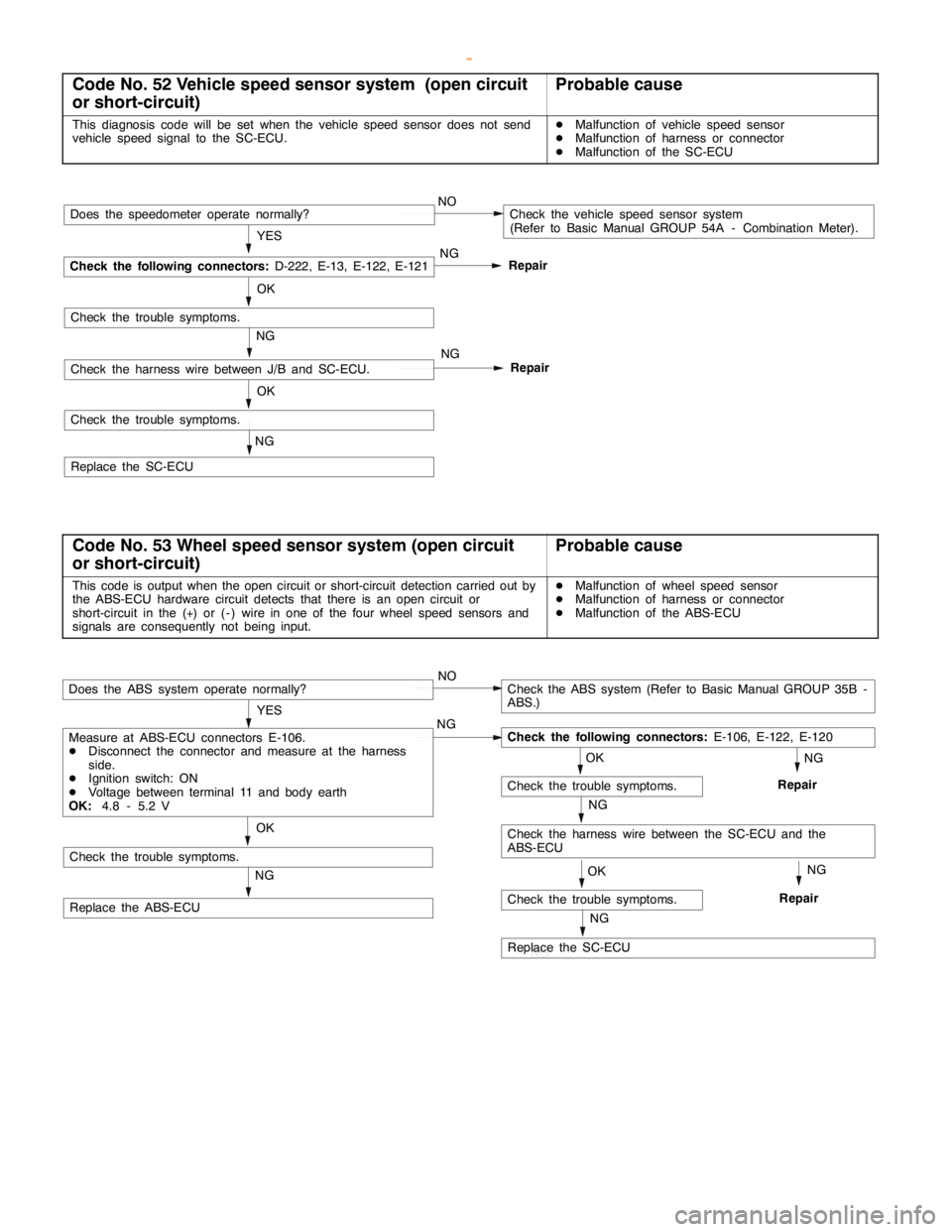
MITSUBISHI SC-Troubleshooting13E-8
Code No. 52 Vehicle speed sensor system (open circuit
or short-circuit)Probable cause
This diagnosis code will be set when the vehicle speed sensor does not send
vehicle speed signal to the SC-ECU.DMalfunction of vehicle speed sensor
DMalfunction of harness or connector
DMalfunction of the SC-ECU
NG
OK
Repair
NG
Check the trouble symptoms.
Replace the SC-ECUNG
OK
Repair YES
NOCheck the vehicle speed sensor system
(Refer to Basic Manual GROUP 54A - Combination Meter).
NG
Check the following connectors:
D-222, E-13, E-122, E-121
Does the speedometer operate normally?
Check the trouble symptoms.
Check the harness wire between J/B and SC-ECU.
Code No. 53 Wheel speed sensor system (open circuit
or short-circuit)Probable cause
This code is output when the open circuit or short-circuit detection carried out by
the ABS-ECU hardware circuit detects that there is an open circuit or
short-circuit in the (+) or ( - ) wire in one of the four wheel speed sensors and
signals are consequently not being input.DMalfunction of wheel speed sensor
DMalfunction of harness or connector
DMalfunction of the ABS-ECU
OK
NG
Check the trouble symptoms.
Replace the ABS-ECU
OK
NG
Check the harness wire between the SC-ECU and the
ABS-ECU
Check the trouble symptoms.
NG NG
YES
NOCheck the ABS system (Refer to Basic Manual GROUP 35B -
ABS.)
Check the following connectors:
E-106, E-122, E-120
Does the ABS system operate normally?
Measure at ABS-ECU connectors E-106.
DDisconnect the connector and measure at the harness
side.
DIgnition switch: ON
DVoltage between terminal 11 and body earth
OK:
4.8 - 5.2 V
RepairNG
OK
NG
Replace the SC-ECU
Check the trouble symptoms.RepairNG
www.WorkshopManuals.co.uk
Purchased from www.WorkshopManuals.co.uk
Page 599 of 1839
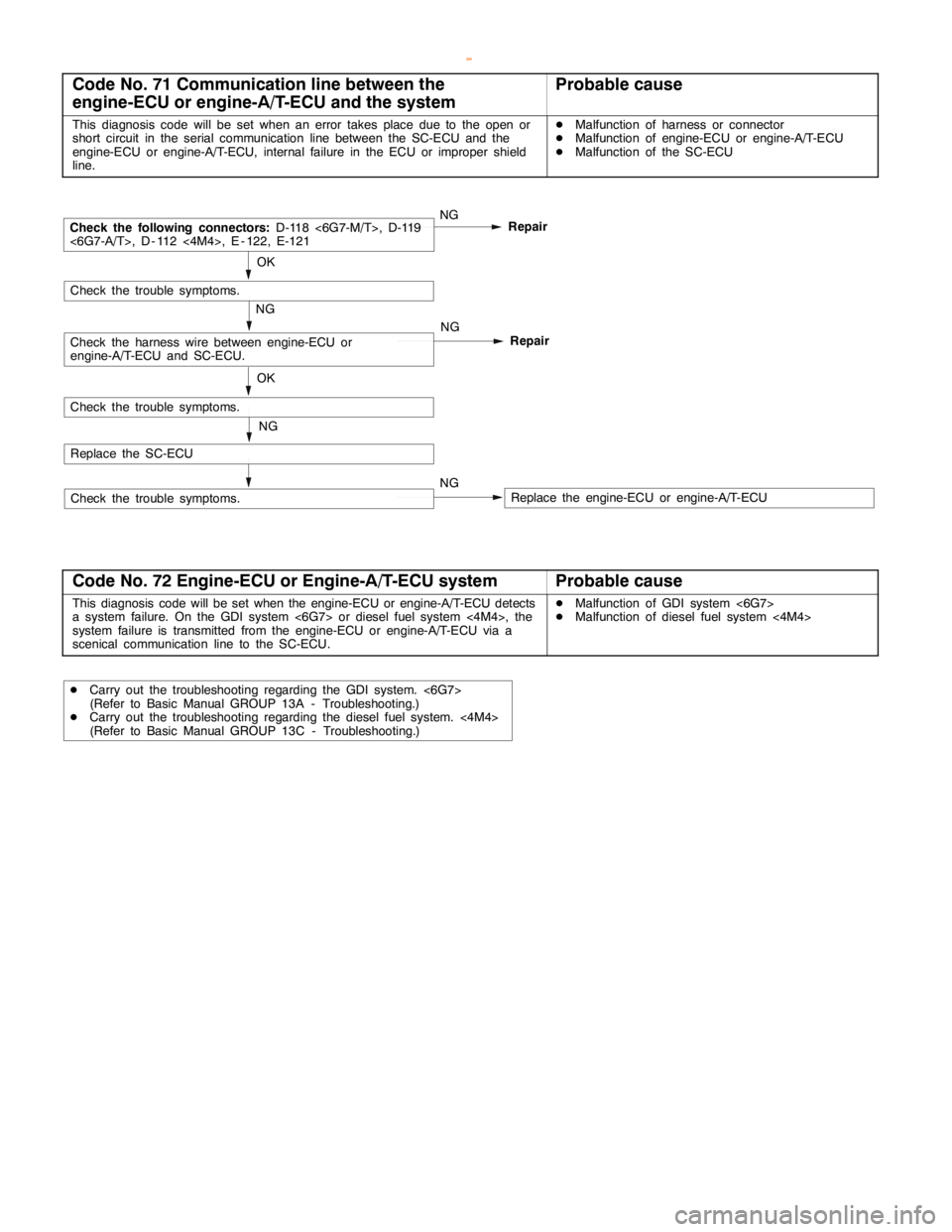
MITSUBISHI SC-Troubleshooting13E-10
Code No. 71 Communication line between the
engine-ECU or engine-A/T-ECU and the systemProbable cause
This diagnosis code will be set when an error takes place due to the open or
short circuit in the serial communication line between the SC-ECU and the
engine-ECU or engine-A/T-ECU, internal failure in the ECU or improper shield
line.DMalfunction of harness or connector
DMalfunction of engine-ECU or engine-A/T-ECU
DMalfunction of the SC-ECU
NG
NG
OK
Repair
NG
Check the trouble symptoms.
Replace the SC-ECUNG
OK
Repair
NGCheck the following connectors:
D-118 <6G7-M/T>, D-119
<6G7-A/T>, D - 112 <4M4>, E - 122, E-121
Check the trouble symptoms.
Check the harness wire between engine-ECU or
engine-A/T-ECU and SC-ECU.
Check the trouble symptoms.Replace the engine-ECU or engine-A/T-ECU
Code No. 72 Engine-ECU or Engine-A/T-ECU systemProbable cause
This diagnosis code will be set when the engine-ECU or engine-A/T-ECU detects
a system failure. On the GDI system <6G7> or diesel fuel system <4M4>, the
system failure is transmitted from the engine-ECU or engine-A/T-ECU via a
scenical communication line to the SC-ECU.DMalfunction of GDI system <6G7>
DMalfunction of diesel fuel system <4M4>
DCarry out the troubleshooting regarding the GDI system. <6G7>
(Refer to Basic Manual GROUP 13A - Troubleshooting.)
DCarry out the troubleshooting regarding the diesel fuel system. <4M4>
(Refer to Basic Manual GROUP 13C - Troubleshooting.)
www.WorkshopManuals.co.uk
Purchased from www.WorkshopManuals.co.uk
Page 601 of 1839
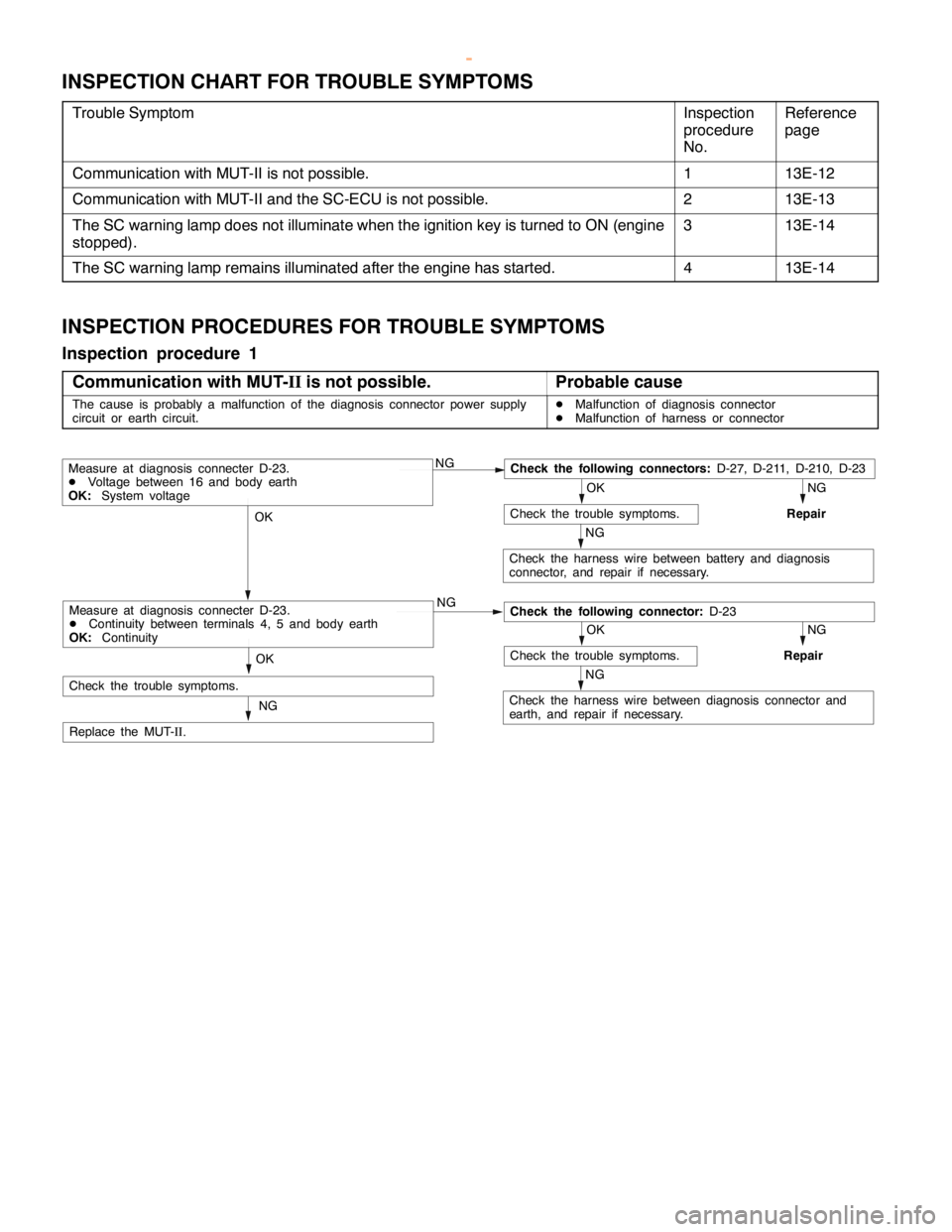
MITSUBISHI SC-Troubleshooting13E-12
INSPECTION CHART FOR TROUBLE SYMPTOMS
Trouble SymptomInspection
procedure
No.Reference
page
Communication with MUT-II is not possible.113E-12
Communication with MUT-II and the SC-ECU is not possible.213E-13
The SC warning lamp does not illuminate when the ignition key is turned to ON (engine
stopped).313E-14
The SC warning lamp remains illuminated after the engine has started.413E-14
INSPECTION PROCEDURES FOR TROUBLE SYMPTOMS
Inspection procedure 1
Communication with MUT-
IIis not possible.
Probable cause
The cause is probably a malfunction of the diagnosis connector power supply
circuit or earth circuit.DMalfunction of diagnosis connector
DMalfunction of harness or connector
NGCheck the following connectors:
D-27, D-211, D-210, D-23
NG
Repair
OK
Check the trouble symptoms.
NG
Check the harness wire between battery and diagnosis
connector, and repair if necessary.
OK
NG
NG
Repair
OK
Check the trouble symptoms.
NG
Check the harness wire between diagnosis connector and
earth, and repair if necessary.
OK
NG
Replace the MUT-
II.
Measure at diagnosis connecter D-23.
DVoltage between 16 and body earth
OK:
System voltage
Check the following connector:
D-23Measure at diagnosis connecter D-23.
DContinuity between terminals 4, 5 and body earth
OK:
Continuity
Check the trouble symptoms.
www.WorkshopManuals.co.uk
Purchased from www.WorkshopManuals.co.uk