Page 1648 of 1839

CHASSIS ELECTRICAL -Radio/Tape Player54A-78
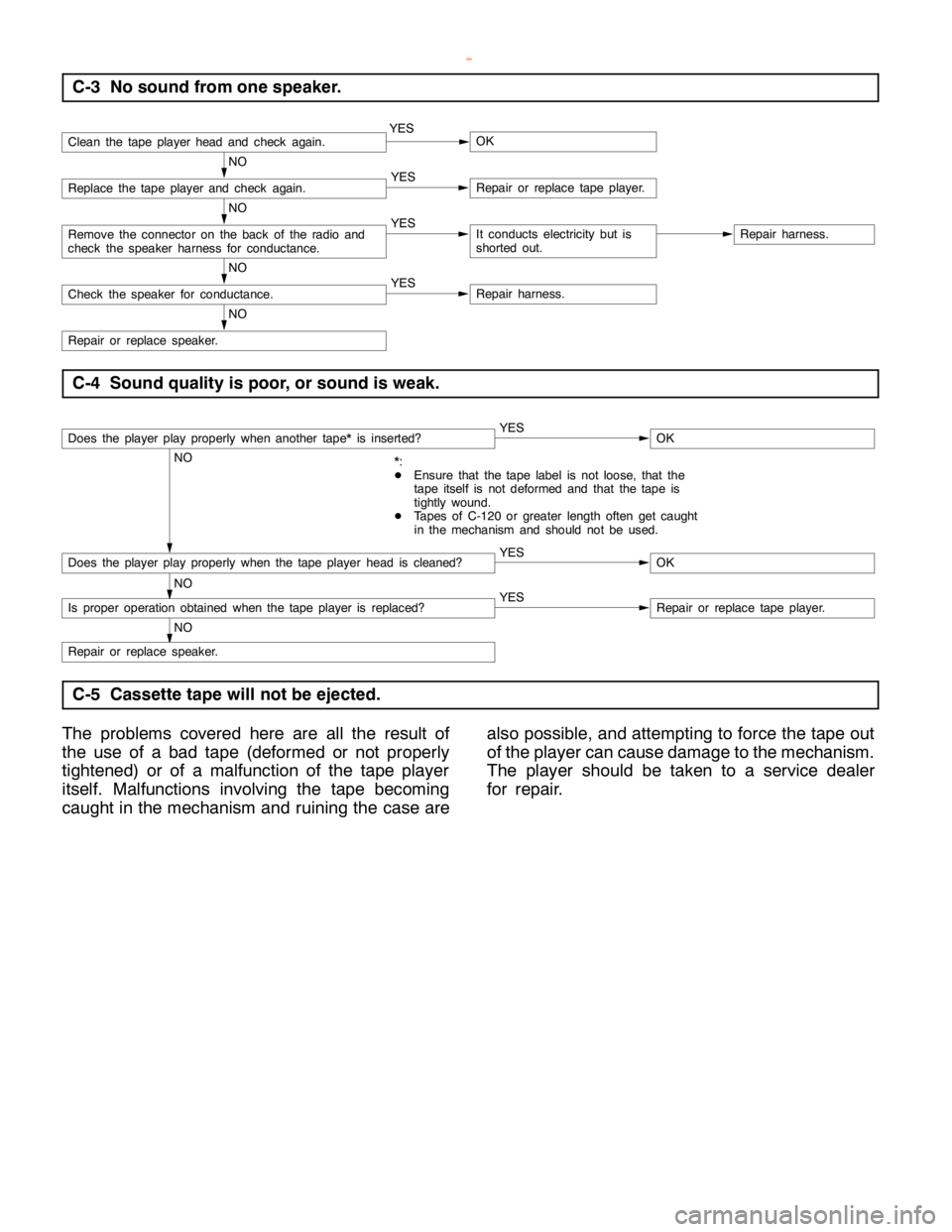
C-3 No sound from one speaker.
Clean the tape playerhead andcheck again.YESOK
NO
Replace the tape player and check again.YESRepair or replace tape player.
NO
Remove the connector on the back of the radio and
check the speaker harness for conductance.YESIt conducts electricity but is
shorted out.Repair harness.
NO
Check the speaker for conductance.YESRepair harness.
NO
Repair or replace speaker.
C-4 Sound quality is poor, or sound is weak.
Does the player play properly when another tape* is inserted?YESOK
NO
*:
DEnsure that the tape label is not loose, that the
tape itself is not deformed and that the tape is
tightly wound.
DTapes of C-120 or greater length often get caught
in the mechanism and should not be used.
Does the player play properly when the tape playerhead is cleaned?YESOK
NO
Is proper operation obtained when the tape player is replaced?YESRepair or replace tape player.
NO
Repair or replace speaker.
C-5 Cassette tape will not be ejected.
The problems covered here are all the result of
the use of a bad tape (deformed or not properly
tightened) or of a malfunction of the tape player
itself. Malfunctions involving the tape becoming
caught in the mechanism and ruining the case arealso possible, and attempting to force the tape out
of the player can cause damage to the mechanism.
The player should be taken to a service dealer
for repair.
www.WorkshopManuals.co.uk
Purchased from www.WorkshopManuals.co.uk
Page 1650 of 1839
CHASSIS ELECTRICAL -Radio/Tape Player54A-80
C-8 Tape gets caught in mechanism*1.
*1
When the tape is caught in the mechanism, the case
may not eject. When this occurs, do not try to force
the tape out as this maydamage the tapeplayer
mechanism. Take the cassette to a service dealer for
repair.
Does the player play OK if the tape*2is changed?YESTape used is bad.
NO
*2
Ensure that the tape label is not loose, that the tape
itself is not deformed and that the tape is tightly
wound. Also, tapes of C-120 or greater length often
get caught in the mechanism and should not be used.
Repair or replace tape player.
www.WorkshopManuals.co.uk
Purchased from www.WorkshopManuals.co.uk
Page 1659 of 1839
Service Bulletins
Click on the applicable bookmark to select the Service Bulletin.
www.WorkshopManuals.co.uk
Purchased from www.WorkshopManuals.co.uk
Page 1680 of 1839

CHASSIS ELECTRICAL -RV Meter54A-19
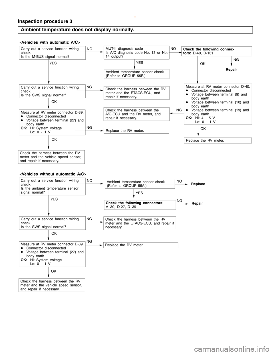
Inspection procedure 3
Ambient temperature does not display normally.
OK
Ambient temperature sensor check
(Refer to GROUP 55B.)
NG
MUT-II diagnosis code
Is A/C diagnosis code No. 13 or No.
14 output?
Repair
Replace the RV meter. NG
Check the harness between the
A/C-ECU and the RV meter, and
repair if necessary.
Carry out a service function wiring
check.
Is the M-BUS signal normal?
YESNO
Replace the RV meter. NGNO
OK
Measure at RV meter connector D-39.
DConnector disconnected
DVoltage between terminal (27) and
body earth
OK:Hi: System voltage
Lo: 0 - 1 V
YES
Check the harness between the RV
meter and the vehicle speed sensor,
and repair if necessary.
Check the following connec-
tors:D-40, D-131
Carry out a service function wiring
check.
Is the SWS signal normal?Check the harness between the RV
meter and the ETACS-ECU, and
repair if necessary.NGMeasure at RV meter connector D-40.
DConnector disconnected
DVoltage between terminal (9) and
body earth
DVoltage between terminal (10) and
body earth
DVoltage between terminal (19) and
body earth
OK:Hi: 4 - 5 V
Lo: 0 - 1 V
OK
OK
Ambient temperature sensor check
(Refer to GROUP 55A.)
NGReplaceCarry out a service function wiring
check.
Is the ambient temperature sensor
signal normal?
YESNO
Replace the RV meter. NGNO
OKMeasure at RV meter connector D-39.
DConnector disconnected
DVoltage between terminal (27) and
body earth
OK:Hi: System voltage
Lo: 0 - 1 V
YES
Check the harness between the RV
meter and the vehicle speed sensor,
and repair if necessary.
Check the following connectors:
A - 30, D-27, D - 39
Carry out a service function wiring
check.
Is the SWS signal normal?Check the harness between the RV
meter and the ETACS-ECU, and repair if
necessary.
OK
NO
Repair
www.WorkshopManuals.co.uk
Purchased from www.WorkshopManuals.co.uk
Page 1681 of 1839
CHASSIS ELECTRICAL -RV Meter54A-20
Inspection procedure 4
Compass does not display normally.
NO
NO
NG
Replace the RV meter.
Is a carrier antenna with a magnet
installed to the vehicle, or is there a
magnet or other metal near the RV
meter?YES
YES
YESEnd (NO abnormality)
NO
YESEnd (NO abnormality)Does operation return to normal
when the magnet or metal is
removed?
NO
Carry out a geomagnetic sensor
mode check in service mode. Does
operation return to normal if
degaussing or calibration is carried
out?OKEnd (NO abnormality)
Does the location have stable
geomagnetism?Is operation normal when the vehicle
is moved to a location with stable
geomagnetism?
OKEnd (NO abnormality)Carry out a geomagnetic sensor
mode check in service mode.
NG
www.WorkshopManuals.co.uk
Purchased from www.WorkshopManuals.co.uk
Page 1682 of 1839

CHASSIS ELECTRICAL -RV Meter54A-21
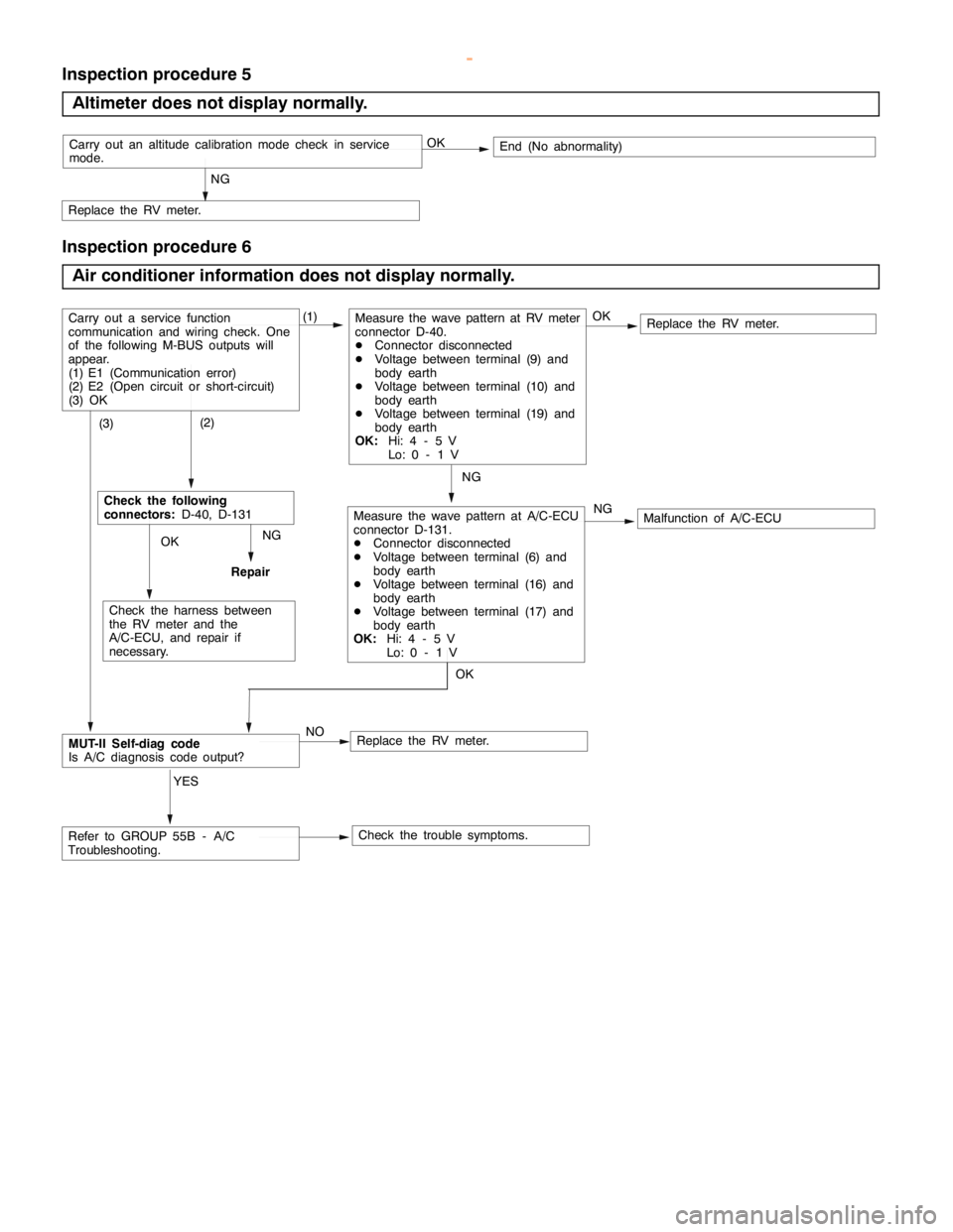
Inspection procedure 5
Altimeter does not display normally.
NG
Replace the RV meter.
OKEnd (No abnormality)Carry out an altitude calibration mode check in service
mode.
Inspection procedure 6
Air conditioner information does not display normally.
NG
Replace the RV meter.
NG
Replace the RV meter.
(1)
Check the trouble symptoms. NO
MUT-II Self-diag code
Is A/C diagnosis code output?
Carry out a service function
communication and wiring check. One
of the following M-BUS outputs will
appear.
(1) E1 (Communication error)
(2) E2 (Open circuit or short-circuit)
(3) OKMeasure the wave pattern at RV meter
connector D-40.
DConnector disconnected
DVoltage between terminal (9) and
body earth
DVoltage between terminal (10) and
body earth
DVoltage between terminal (19) and
body earth
OK:Hi: 4 - 5 V
Lo: 0 - 1 V
Malfunction of A/C-ECU OKMeasure the wave pattern at A/C-ECU
connector D-131.
DConnector disconnected
DVoltage between terminal (6) and
body earth
DVoltage between terminal (16) and
body earth
DVoltage between terminal (17) and
body earth
OK:Hi: 4 - 5 V
Lo: 0 - 1 V (2)Check the following
connectors:D-40, D-131
NG
OK
Check the harness between
the RV meter and the
A/C-ECU, and repair if
necessary. (3)
Refer to GROUP 55B - A/C
Troubleshooting.YES
OK
Repair
www.WorkshopManuals.co.uk
Purchased from www.WorkshopManuals.co.uk
Page 1683 of 1839

CHASSIS ELECTRICAL -RV Meter54A-22
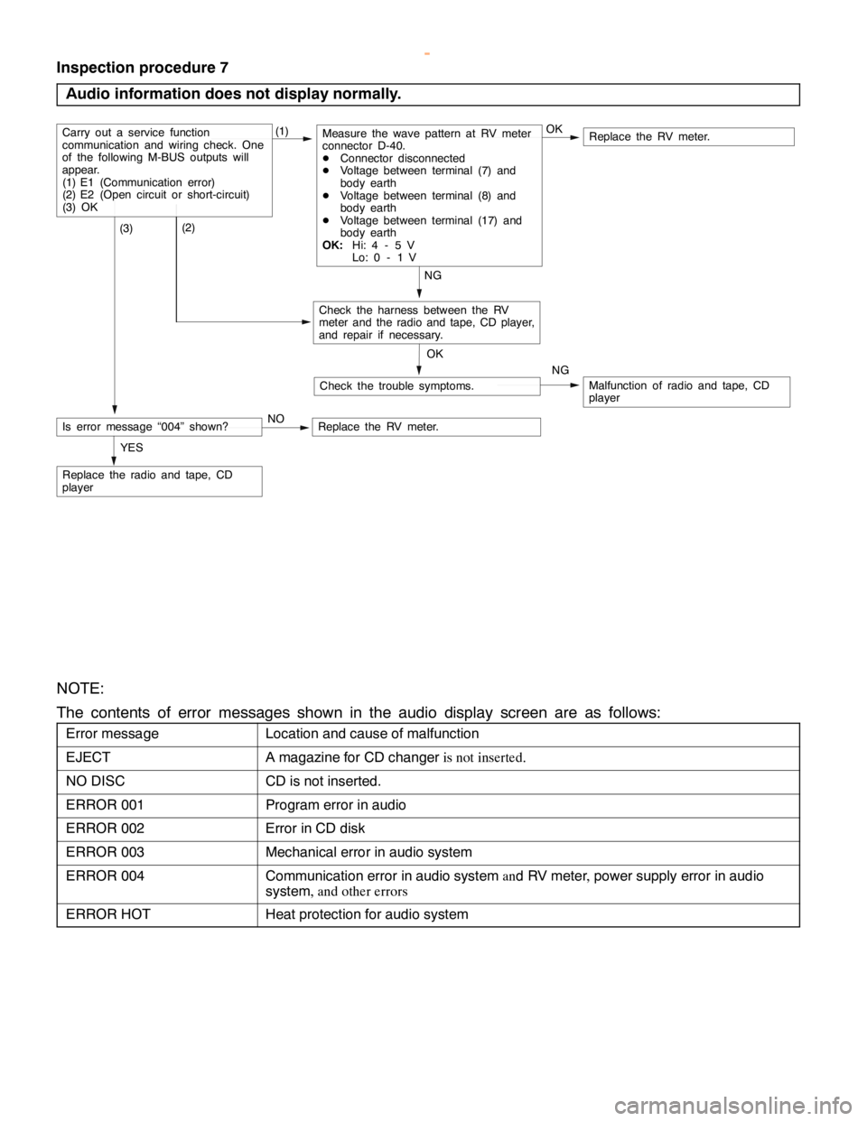
Inspection procedure 7
Audio information does not display normally.
Replace the RV meter.
NG
Replace the radio and tape, CD
player
(1)
Check the trouble symptoms.
Carry out a service function
communication and wiring check. One
of the following M-BUS outputs will
appear.
(1) E1 (Communication error)
(2) E2 (Open circuit or short-circuit)
(3) OKMeasure the wave pattern at RV meter
connector D-40.
DConnector disconnected
DVoltage between terminal (7) and
body earth
DVoltage between terminal (8) and
body earth
DVoltage between terminal (17) and
body earth
OK:Hi: 4 - 5 V
Lo: 0 - 1 V
Malfunction of radio and tape, CD
player OK
(2)
Check the harness between the RV
meter and the radio and tape, CD player,
and repair if necessary. (3)
YESOK
NG
Is error message “004” shown?NOReplace the RV meter.
NOTE:
The contents of error messages shown in the audio display screen are as follows:
Error messageLocation and cause of malfunction
EJECTA magazine for CD changeris not inserted.
NO DISCCD is not inserted.
ERROR 001Program error in audio
ERROR 002Error in CD disk
ERROR 003Mechanical error in audio system
ERROR 004Communication error in audio systemand RV meter,power supply error in audio
system, and other errors
ERROR HOTHeat protection for audio system
www.WorkshopManuals.co.uk
Purchased from www.WorkshopManuals.co.uk
Page 1687 of 1839
54B-1
SMART WIRING
SYSTEM (SWS)
CONTENTS
GENERAL INFORMATION 2................
SPECIAL TOOLS 7........................
TROUBLESHOOTING 8....................
Standard Flow of Diagnostic
Troubleshooting 8...........................
Diagnostic Function 8........................
Diagnosis Code Chart 9.....................Diagnosis Code Inspection Procedures 10.....
Trouble Symptom Chart 13...................
Inspection Procedure for Trouble
Symptoms 17...............................
Check at ECU Terminals 54..................
ON-VEHICLE SERVICE 60.................
Adjustment Procedures for SWS Function 60..
www.WorkshopManuals.co.uk
Purchased from www.WorkshopManuals.co.uk