2000 MITSUBISHI MONTERO relay
[x] Cancel search: relayPage 1720 of 1839
SWS -TroubleshootingSWS -Troubleshooting54B-34
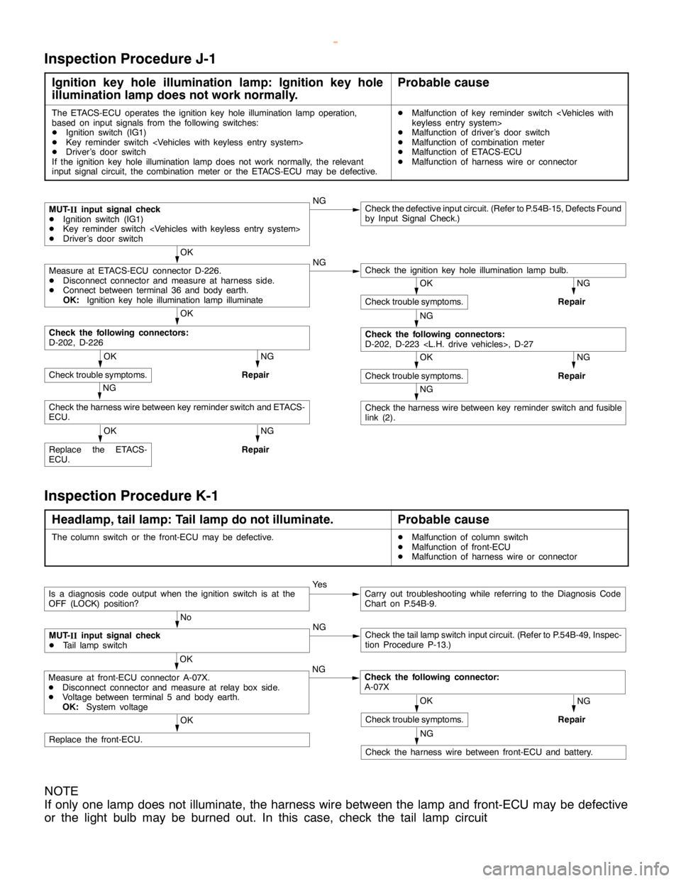
Inspection Procedure J-1
Ignition key hole illumination lamp: Ignition key hole
illumination lamp does not work normally.Probable cause
The ETACS-ECU operates the ignition keyhole illumination lamp operation,
based on input signals from the following switches:
DIgnition switch (IG1)
DKey reminder switch
DDriver’s door switch
If the ignition key hole illumination lampdoes not work normally, the relevant
input signal circuit, the combination meter or the ETACS-ECU may be defective.DMalfunction of key reminder switch
DMalfunction of driver’s door switch
DMalfunction of combination meter
DMalfunction of ETACS-ECU
DMalfunction of harness wire or connector
NGCheck the defective input circuit. (Refer to P.54B-15, Defects Found
by Input Signal Check.)
OK
NG
NG
Repair
OK
NG
Repair
NG
NG
Repair
OK
Replace the ETACS-
ECU.
NG
Repair
NG
Check the harness wire between key reminder switch and fusible
link (2).
OK
Check trouble symptoms.
NG
Check the following connectors:
D-202, D-223
OK
Check trouble symptoms.
Check the harness wire between key reminder switch and ETACS-
ECU.
OK
Check trouble symptoms.
Check the following connectors:
D-202, D-226
Check the ignition keyhole illumination lamp bulb.Measure at ETACS-ECU connector D-226.
DDisconnect connector and measure at harness side.
DConnect between terminal 36 and body earth.
OK:Ignition key hole illumination lamp illuminate
MUT-
IIinput signal check
DIgnition switch (IG1)
DKey reminder switch
DDriver’s door switch
Inspection Procedure K-1
Headlamp, tail lamp: Tail lamp do not illuminate.Probable cause
The column switch or the front-ECU may be defective.DMalfunction of column switch
DMalfunction of front-ECU
DMalfunction of harness wire or connector
OK
Replace the front-ECU.
Ye sCarry out troubleshooting while referring to the Diagnosis Code
Chart on P.54B-9.
No
NG
Check the taillampswitch input circuit. (Refer to P.54B-49, Inspec-
tion Procedure P-13.)
NG
Repair
NG
Check the harness wire between front-ECU and battery.
OK
Check trouble symptoms.
OK
NG
Check the following connector:
A-07XMeasure at front-ECU connector A-07X.
DDisconnect connector and measure at relay box side.
DVoltage between terminal 5 and body earth.
OK:System voltage
MUT-
IIinput signal check
DTail lampswitch
Is a diagnosis code output when the ignition switch is at the
OFF (LOCK) position?
NOTE
If only one lamp does not illuminate, the harness wire between the lamp and front-ECU may be defective
or the light bulb may be burned out. In this case, check the tail lamp circuit
www.WorkshopManuals.co.uk
Purchased from www.WorkshopManuals.co.uk
Page 1721 of 1839
SWS -Troubleshooting54B-35
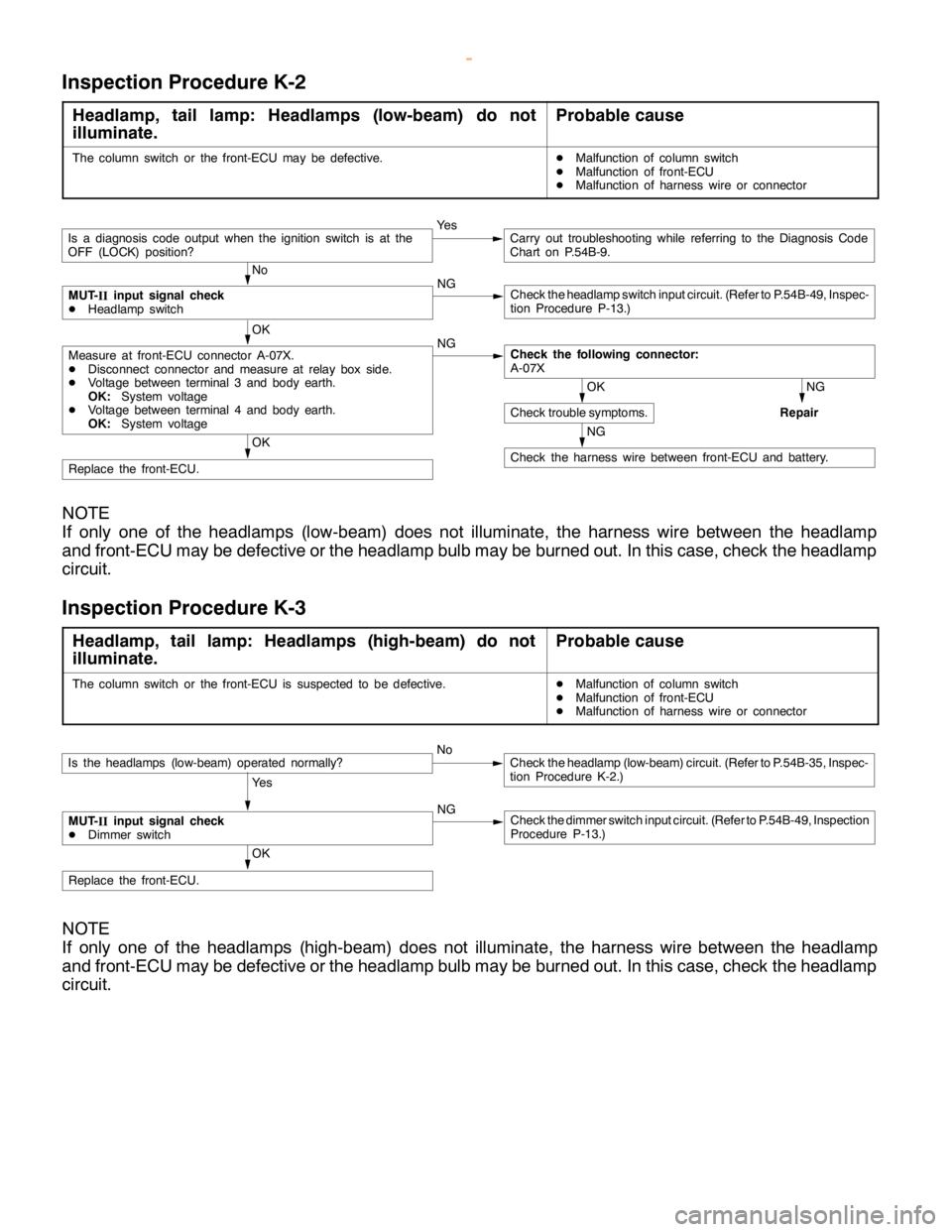
Inspection Procedure K-2
Headlamp, tail lamp: Headlamps (low-beam) do not
illuminate.Probable cause
The column switch or the front-ECU may be defective.DMalfunction of column switch
DMalfunction of front-ECU
DMalfunction of harness wire or connector
OK
Replace the front-ECU.
No
NG
Check theheadlampswitch input circuit. (Refer to P.54B-49, Inspec-
tion Procedure P-13.)
Ye sCarry out troubleshooting while referring to the Diagnosis Code
Chart on P.54B-9.
NG
Repair
NG
Check the harness wire between front-ECU and battery.
OK
Check trouble symptoms.
OK
NG
Check the following connector:
A-07XMeasure at front-ECU connector A-07X.
DDisconnect connector and measure at relay box side.
DVoltage between terminal 3 and body earth.
OK:System voltage
DVoltage between terminal 4 and body earth.
OK:System voltage
MUT-
IIinput signal check
DHeadlamp switch
Is a diagnosis code output when the ignition switch is at the
OFF (LOCK) position?
NOTE
If only one of the headlamps (low-beam) does not illuminate, the harness wire between the headlamp
and front-ECU may be defective or the headlamp bulb may be burned out. In this case, check the headlamp
circuit.
Inspection Procedure K-3
Headlamp, tail lamp: Headlamps (high-beam) do not
illuminate.Probable cause
The column switch or the front-ECU is suspected to be defective.DMalfunction of column switch
DMalfunction of front-ECU
DMalfunction of harness wire or connector
OK
Replace the front-ECU.
Is the headlamps (low-beam) operated normally?NoCheck theheadlamp (low-beam)circuit. (Refer to P.54B-35, Inspec-
tion Procedure K-2.)
Ye s
MUT-
IIinput signal check
DDimmer switchNGCheck the dimmer switch input circuit. (Refer to P.54B-49, Inspection
Procedure P-13.)
NOTE
If only one of the headlamps (high-beam) does not illuminate, the harness wire between the headlamp
and front-ECU may be defective or the headlamp bulb may be burned out. In this case, check the headlamp
circuit.
www.WorkshopManuals.co.uk
Purchased from www.WorkshopManuals.co.uk
Page 1725 of 1839
SWS -TroubleshootingSWS -Troubleshooting54B-39
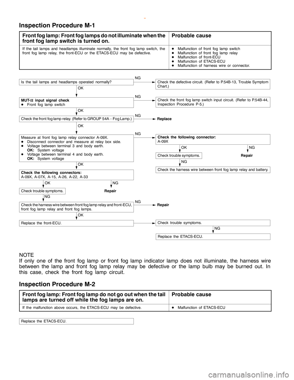
Inspection Procedure M-1
Front fog lamp: Front fog lamps do not illuminate when the
front fog lamp switch is turned on.Probable cause
If the tail lamps and headlamps illuminate normally, the front fog lampswitch, the
front fog lamprelay, the front-ECU or the ETACS-ECU may be defective.DMalfunction of front fog lampswitch
DMalfunction of front fog lamprelay
DMalfunction of front-ECU
DMalfunction of ETACS-ECU
DMalfunction of harness wire or connector.
OK
Replace the front-ECU.Check trouble symptoms.
NGCheck the defective circuit. (Refer to P.54B-13, Trouble Symptom
Chart.)
OK
NG
Check the front foglampswitch input circuit. (Refer to P.54B-44,
Inspection Procedure P-5.)
OK
NG
NG
Repair
NG
Check the harness wire between front foglamprelay and battery.
OK
NG
Repair
NG
Check the harness wire between front foglamprelay and front-ECU,
front fog lamprelay and front fog lamps.NG
Repair
OK
Check trouble symptoms.
Check the following connectors:
A-09X, A-07X, A-15, A-26, A-22, A-33
OK
Check trouble symptoms.
Check the following connector:
A-09XMeasure at front fog lamprelay connector A-09X.
DDisconnect connector and measure at relay box side.
DVoltage between terminal 3 and body earth.
OK:System voltage
DVoltage between terminal 4 and body earth.
OK:System voltage
OK
Check the front foglamprelay. (Refer to GROUP 54A – Fog Lamp.)NG
Replace
MUT-
IIinput signal check
DFront fog lampswitch
Is the tail lamps and headlamps operated normally?
NG
Replace the ETACS-ECU.
NOTE
If only one of the front fog lamp or front fog lamp indicator lamp does not illuminate, the harness wire
between the lamp and front fog lamp relay may be defective or the lamp bulb may be burned out. In
this case, check the front fog lamp circuit.
Inspection Procedure M-2
Front fog lamp: Front fog lamp do not go out when the tail
lamps are turned off while the fog lamps are on.Probable cause
If the malfunction above occurs, the ETACS-ECU may be defective.DMalfunction of ETACS-ECU
Replace the ETACS-ECU.
www.WorkshopManuals.co.uk
Purchased from www.WorkshopManuals.co.uk
Page 1726 of 1839
SWS -Troubleshooting54B-40
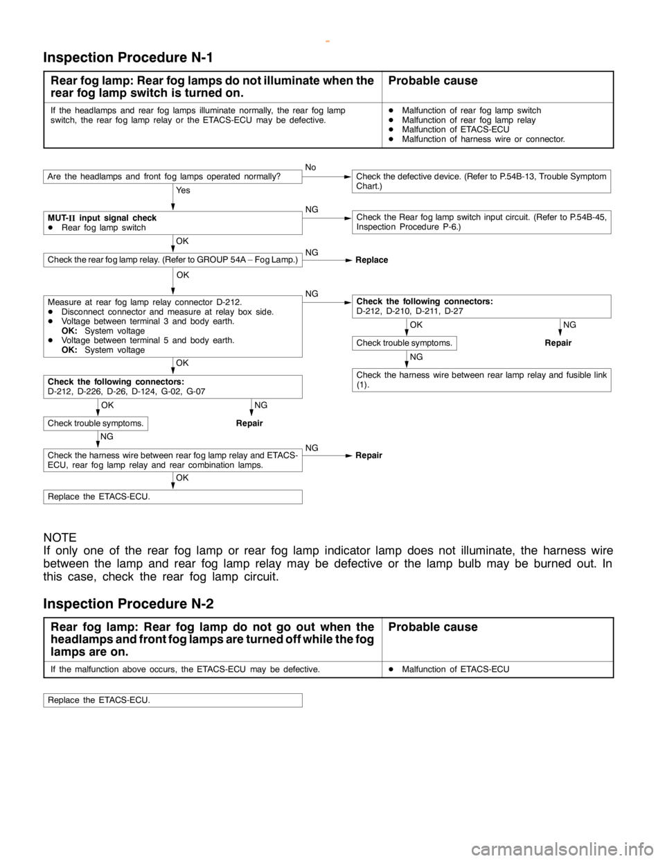
Inspection Procedure N-1
Rear fog lamp: Rear fog lamps do not illuminate when the
rear fog lamp switch is turned on.Probable cause
If the headlamps and rear fog lamps illuminate normally, the rear foglamp
switch, the rear foglamprelay or the ETACS-ECU may be defective.DMalfunction of rear foglampswitch
DMalfunction of rear foglamprelay
DMalfunction of ETACS-ECU
DMalfunction of harness wire or connector.
NoCheck the defective device. (Refer to P.54B-13, Trouble Symptom
Chart.)
Ye s
NG
Check the Rear foglampswitch input circuit. (Refer to P.54B-45,
Inspection Procedure P-6.)
OK
NG
Replace
OK
NG
NG
Repair
NG
Check the harness wire between rearlamprelay and fusible link
(1).
OK
NG
Repair
OK
Check trouble symptoms.
Check the following connectors:
D-212, D-226, D-26, D-124, G-02, G-07
OK
Check trouble symptoms.
Check the following connectors:
D-212, D-210, D-211, D-27Measure at rear foglamprelay connector D-212.
DDisconnect connector and measure at relay box side.
DVoltage between terminal 3 and body earth.
OK:System voltage
DVoltage between terminal 5 and body earth.
OK:System voltage
Check the rear foglamprelay. (Refer to GROUP 54A – Fog Lamp.)
MUT-
IIinput signal check
DRear foglampswitch
Are the headlamps and front fog lamps operated normally?
OK
Replace the ETACS-ECU.
NG
Check the harness wire between rear foglamprelay and ETACS-
ECU, rear foglamprelay and rear combination lamps.NG
Repair
NOTE
If only one of the rear fog lamp or rear fog lamp indicator lamp does not illuminate, the harness wire
between the lamp and rear fog lamp relay may be defective or the lamp bulb may be burned out. In
this case, check the rear fog lamp circuit.
Inspection Procedure N-2
Rear fog lamp: Rear fog lamp do not go out when the
headlamps and front fog lamps are turned off while the fog
lamps are on.Probable cause
If the malfunction above occurs, the ETACS-ECU may be defective.DMalfunction of ETACS-ECU
Replace the ETACS-ECU.
www.WorkshopManuals.co.uk
Purchased from www.WorkshopManuals.co.uk
Page 1737 of 1839
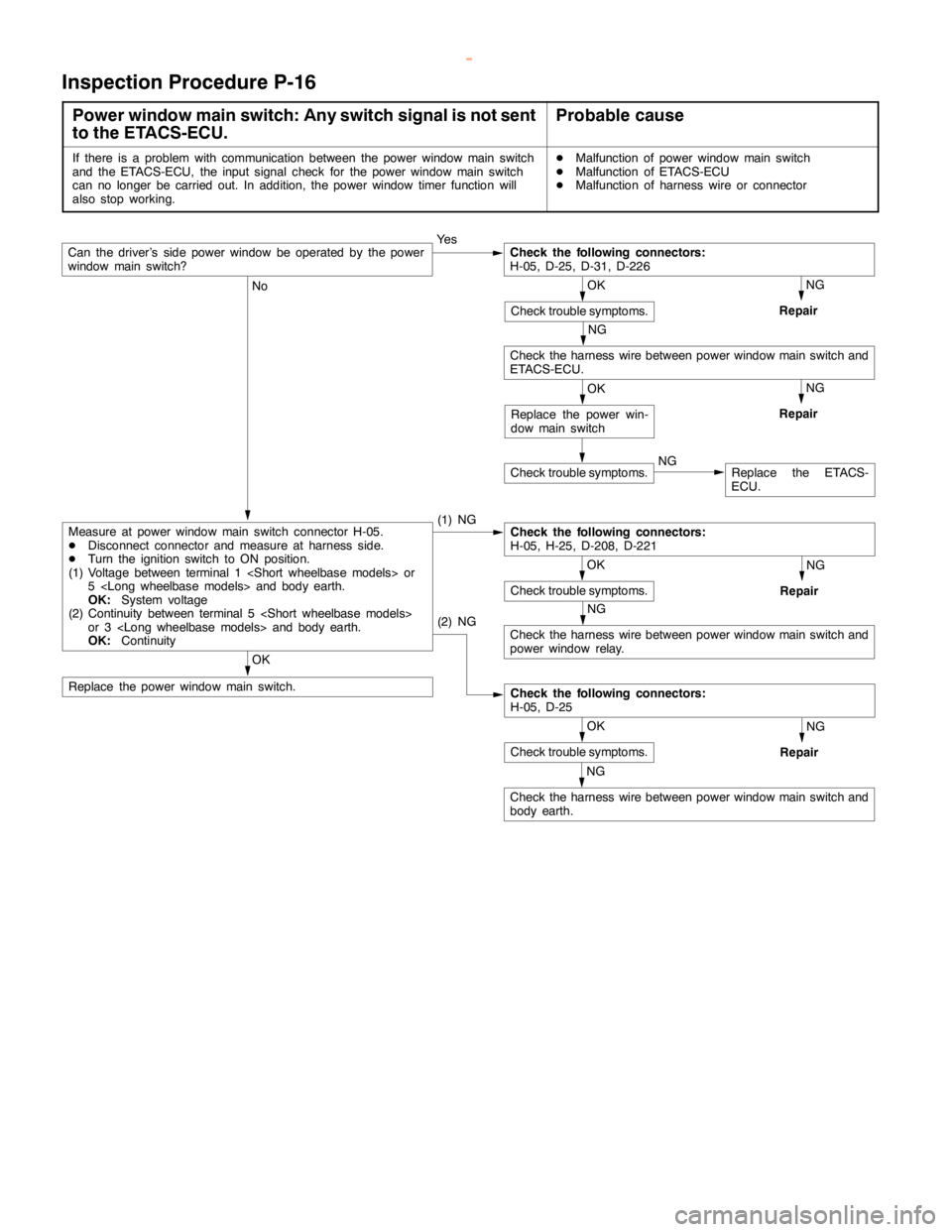
SWS -Troubleshooting54B-51
Inspection Procedure P-16
Power window main switch: Any switch signal is not sent
to the ETACS-ECU.Probable cause
If there is a problem with communication between the power windowmainswitch
and the ETACS-ECU, the input signal check for the power windowmainswitch
can no longer be carried out. In addition, the power window timer function will
also stop working.DMalfunction of power windowmainswitch
DMalfunction of ETACS-ECU
DMalfunction of harness wire or connector
Ye s
NG
Repair
NG
No
(1) NG
NG
Repair
NG
Check the harness wire between power windowmainswitch and
power window relay.
OK
Replace the power windowmainswitch.
NG
Repair
NG
Check the harness wire between power windowmainswitch and
body earth.
NG
Repair
Check trouble symptoms.NGReplace the ETACS-
ECU.
OK
Check trouble symptoms.
(2) NG
Check the following connectors:
H-05, D-25
OK
Check trouble symptoms.
Check the following connectors:
H-05, H-25, D-208, D-221Measure at power windowmainswitch connector H-05.
DDisconnect connector and measure at harness side.
DTurn the ignition switch to ON position.
(1) Voltage between terminal 1
5
OK:System voltage
(2) Continuity between terminal 5
or 3
OK:Continuity
OK
Replace the power win-
dow mainswitch
Check the harness wire between power windowmainswitch and
ETACS-ECU.
OK
Check trouble symptoms.
Check the following connectors:
H-05, D-25, D-31, D-226Can the driver’s side power window be operated by the power
window mainswitch?
www.WorkshopManuals.co.uk
Purchased from www.WorkshopManuals.co.uk
Page 1741 of 1839

SWS -Troubleshooting54B-55
Terminal
No.Normal condition Checking requirements Check items
26Key reminder switch signal inputKey reminder switch: ON (Ignition key
removed)0V
27Hazard warning lamp switch signal
inputHazard warning lamp switch: ON0V
29Recognition line of daytime running
lamp (DRL)
31Data request signal outputAlways0 - 5 V (pulse
signal)
34Windshield intermittent wiper interval
adjusting knob signal inputIgnition switch: ACC,
Windshield intermittent wiper interval
adjusting knob: FAST®SLOW0®2.5 V
35Back-up lamp switch signal input
Shift lever: RSystem voltage
Inhibitor switch (reverse) signal input
Ignition switch: ON,
Selector lever: RSystem voltage
36Ignition key hole illumination lamp
outputWhen ignition key hole illumination
lamp is lighted2 V or less
37Diagnosis code or input signal check
outputWhen diagnosis code is output0 - 12 V (pulse
signal)
When input signal check is output0, 12 V (When input
pulse signal is
changed)
40Rear fog lamp relay outputWhen rear fog lamp is lighted2 V or less
53Front passenger’s and back door lock
key cylinder switch (LOCK) signal inputFront passenger’s or back door lock key
cylinder switch: LOCK0V
54Front passenger’s and back door lock
key cylinder switch (UNLOCK) signal
inputFront passenger’s or back door lock
switch: UNLOCK0V
55Driver’s door lock actuator switch
(LOCK) signal inputDriver’s door lock actuator switch:
LOCK0V
56Driver’s door lock actuator switch
(UNLOCK) signal inputDriver’s door lock actuator switch:
UNLCOK0V
www.WorkshopManuals.co.uk
Purchased from www.WorkshopManuals.co.uk
Page 1748 of 1839

55A-2
HEATER, AIR
CONDITIONER AND
VENTILATION
CONTENTS
SERVICE SPECIFICATIONS 3.................
LUBRICANTS 3..............................
TROUBLESHOOTING
TROUBLESHOOTING
ON-VEHICLE SERVICE 9.....................
Refrigerant Level Test through Performance Test 9.
Magnetic Clutch Test 10.........................
Receiver Drier Test 10..........................
Compressor Drive Belt Adjustment 10.............
Dual Pressure Switch Check 10..................
Charging 11...................................
Performance Test 15............................
Front Blower Relay and Rear Blower Relay
Continuity Check 18............................
Continuity Check of A/C Compressor Relay and
Condernser Fan Relay 18.......................
PTC Heater Relay Continuity Check 19...........
Idle-up Operation Check
Vacuum Actuator Check
Idle-up Solenoid Valve Check 21.................
Clean Air Filter Replacement Procedure 22........
FRONT A/C 23..............................
Air Conditioner Control Panel Assembly and
A/C Switch 23.................................
Heater Unit and Blower Assembly 26.............
Blower Motor and Resistor 29....................
Inside/Outside Air Changeover Damper Motor 30...
Automatic Compressor-ECU and
Air Thermo Sensor Assembly 31.................
REAR HEATER AND REAR COOLER 32.....
Rear A/C Switch, Front Rear Fan Switch 32.......
Rear A/C Control Unit 34........................
Rear Heater Unit 34............................
Rear Heater Unit and Rear Blower Assembly 37....
HEAT SWITCH 40...........................
COMPRESSOR 41...........................
CONDENSER ASSEMBLY AND
CONDENSER FAN 45........................
REFRIGERANT LINE 47.....................
ENGINE COOLANT TEMPERATURE SWITCH
51 ..........................................
IDLE-UP SYSTEM 53........................
DUCTS 54..................................
VENTILATION 56............................
www.WorkshopManuals.co.uk
Purchased from www.WorkshopManuals.co.uk
Page 1750 of 1839

HEATER, AIR CONDITIONER AND VENTILATION - Troubleshooting55A-4
TROUBLESHOOTING
Trouble symp-
tomProbable causeRemedyRefer-
ence
page
The air condi-Malfunction of fuseReplace the fuse.–
tioner does notMalfunction of harness or connectorRepair the harness or connector.–work.
Refrigerant leak or overfilling of refrigerantReplenish the refrigerant, repair the leak
or take out some of the refrigerant.–
A/C compressor relay is defective.Replace the A/C compressor relay.55A-18
The A/C compressor magnetic clutch is
defective.Replace the A/C compressor.55A-10
The dual pressure switch is defective.Replace the dual-pressure switch.55A-10
The A/C switch is defective.Replace the heater control assembly.55A-24
The blower switch is defective.Replace the heater control assembly.55A-24
The air thermo sensor is defective.Replace the automatic compressor-ECU
and the air thermo sensor assembly.55A-31
The automatic compressor-ECU is defec-
tive.Replace the automatic compressor-ECU
and the air thermo sensor assembly.55A-6
The engine-ECU is defective.Replace the engine-ECU.–
When the A/C
is operating,Refrigerant leakReplenish the refrigerant and repair the
leak.–
temperature
inside the pas-The dual pressure switch is defective.Replace the dual-pressure switch.55A-10inside the pas-
senger
The condenser fan relay is defective.Replace the condenser fan relay.55A-18compartment
doesn’t de-
A/C compressor relay is defective.Replace the A/C compressor relay.55A-18
crease (cool
air is not
emitted).The A/C compressor magnetic clutch is
defective.Replace the A/C compressor.55A-10
When the A/C
is operating,
temperature
inside the pas-
senger
compartment
doesn’t in-
crease (warm
air is not
emitted).Malfunction of the air thermo sensorReplace the automatic compressor-ECU
and the air thermo sensor assembly.55A-31
The blowerMalfunction of fuseReplace the fuse.–
motor does notMalfunction of harness or connectorRepair the harness or connector.–run.
The blower relay is defective.Replace the blower relay.55A-18
The blower motor is defective.Replace the blower motor.55A-29
The blower switch is defective.Replace the heater control assembly.55A-24
Malfunction of the resistorReplace the resistor.55A-29
The automatic compressor-ECU is defec-
tive.Replace the automatic compressor-ECU
and the air thermo sensor assembly.55A-6
www.WorkshopManuals.co.uk
Purchased from www.WorkshopManuals.co.uk