2000 MITSUBISHI MONTERO relay
[x] Cancel search: relayPage 988 of 1839

AUTOMATIC TRANSMISSION -Troubleshooting
DATA LIST REFERENCE TABLE
Item
No.Check itemInspection conditionsNormal condition
1Accelerator pedalEngine: StoppedAccelerator pedal: Fully closed985 - 1,085 mV
position sensor
(APS)Selector lever position:
PAccelerator pedal: DepressedGradually increases from
the above value.
Accelerator pedal: Fully open4000 mV or higher
2Front propeller shaft
speed sensorTransfer position: 4WDDriving at a constant speed of
30 km/h30 km/h
3Rear propeller shaftTransfer position: 4WDDriving at a constant speed of30 km/h3Rear propeller shaft
speed sensorTransfer position: 4WDDriving at a constant speed of
30 km/h30 km/h
4Difference between
front and rear pro-
peller shaft speedsTransfer position: 4WDDriving at a constant speed of
30 km/hWithin 5 km/h
5Vehicle speedIdling in 1st (Vehicle stopped)0 km/h
Driving at a constant speed of 50 km/h in 3rd50 km/h
6Transfer lever posi-Ignition switch: ONTransfer shift lever position: 2H2H
tionEngine: StoppedTransfer shift lever position: 4H4H
Transfer shift lever position:
4HLc4HLc
Transfer shift lever position:
4LLc4LLc
7Transfer positionDriving at a constant
speed of 10 km/hTransfer shift lever position:
2H®4H2H - 4H®4H
Transfer shift lever position:
4H®4HLc4H - 4HL®4HL
Engine: Stopped
Selector lever position:Transfer shift lever position:
4HLc®4LLc4HL - 4LL®4LL
NTransfer shift lever position:
4LLc®4HLc4HL - 4LL®4HL
Driving at a constant
speed of 10 km/hTransfer shift lever position:
4HLc®4H4H - 4HL®4H
Transfer shift lever position:
4H®2H2H - 4H®2H
8Main relay voltageIgnition switch: ONSystem voltage (V)
9Ignition voltageIgnition switch: ONSystem voltage (V)
10Shift actuator cur-
rentDuring transfer selection (while motor is running)0A®0.2 A®0A
11Target currentDuring transfer selection (while motor is running)0A®1.5 A®0A
12Shift actuator volt-
ageIgnition switch: ON
Selector lever position: N
Transfer shift lever position: 2H®4H (or 4H®4HLc,
4HLc®4LLc)System voltage (V)
Ignition switch: ON
Selector lever position: N
Transfer shift lever position: 4LLc®4HLc (or 4HLc®4H,
4H®2H)System voltage (V)
www.WorkshopManuals.co.uk
Purchased from www.WorkshopManuals.co.uk
Page 1210 of 1839

35A-2
BASIC BRAKE
SYSTEM
CONTENTS
GENERAL INFORMATION 3..................
SERVICE SPECIFICATIONS 5.................
LUBRICANTS 6..............................
SPECIAL TOOLS 6..........................
TROUBLESHOOTING
ON-VEHICLE SERVICE 19...................
Brake Pedal Check and Adjustment 19..........
Hydraulic Brake Booster (HBB) Operation Check
HBB Check
HBB Motor Relay Continuity Check
Brake Booster Operating Test
Check Valve Operation Check
Load Sensing Spring Length Check and
Adjustment
Load Sensing Proportioning Valve Function
Test
Bleeding
Brake Fluid Level Sensor Check 30.............
Brake Booster Vacuum Switch Check
Disc Brake Pad Check and Replacement 31.....
Disc Brake Rotor Check 32.....................
Brake Disc Thickness Check 32.................
Brake Disc Run-out Check and Correction 33....
BRAKE PEDAL 34..........................
HYDRAULIC BRAKE BOOSTER (HBB)
HBB BUZZER
MASTER CYLINDER AND BRAKE
BOOSTER
Master Cylinder 43.............................
FRONT DISC BRAKE 44....................
REAR DISC BRAKE 49......................
LOAD SENSING PROPORTIONING
VALVE
www.WorkshopManuals.co.uk
Purchased from www.WorkshopManuals.co.uk
Page 1217 of 1839

BASIC BRAKE SYSTEM -Troubleshooting35A-9
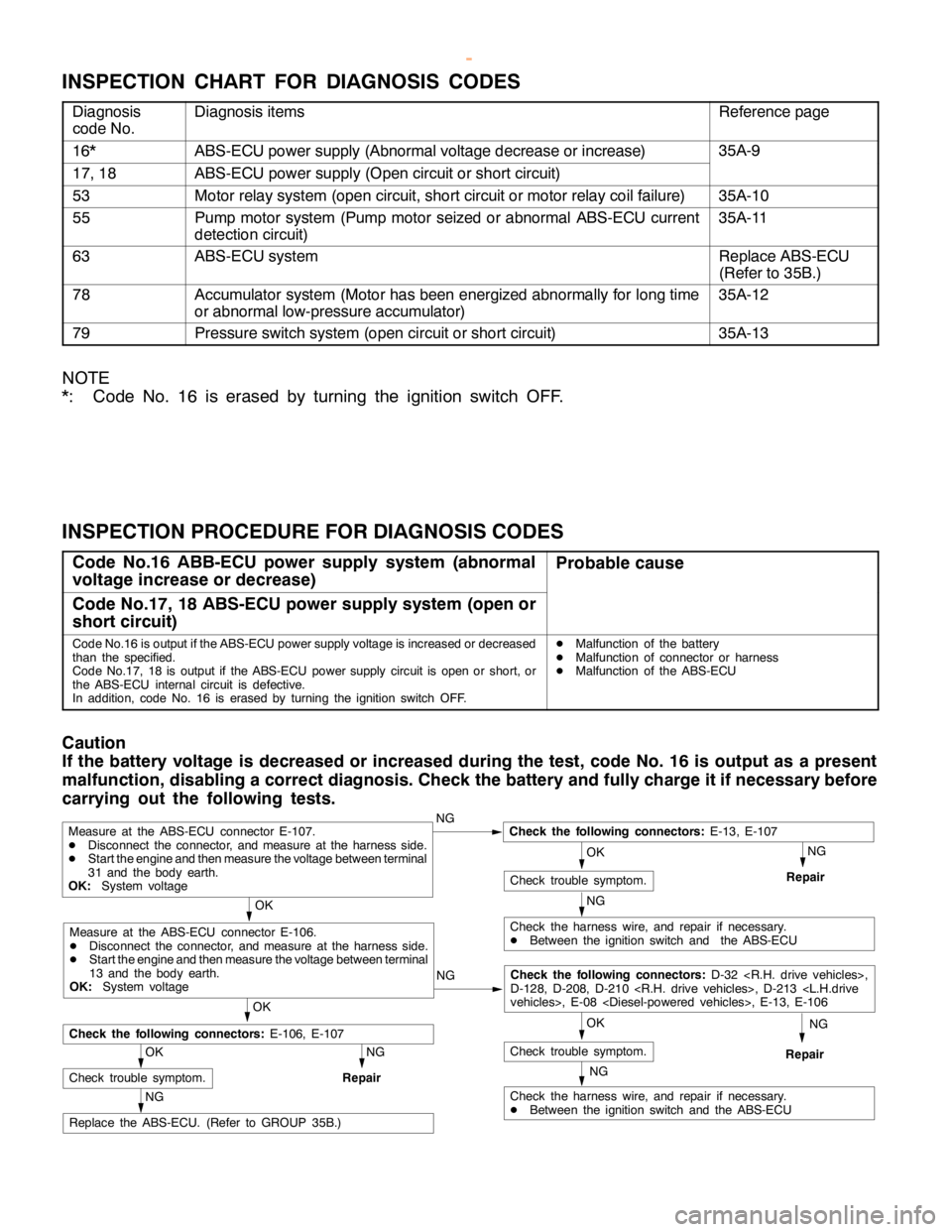
INSPECTION CHART FOR DIAGNOSIS CODES
Diagnosis
code No.Diagnosis itemsReference page
16*ABS-ECU power supply (Abnormal voltage decrease or increase)35A-9
17, 18ABS-ECU power supply (Open circuit or short circuit)
53Motor relay system (open circuit, short circuit or motor relay coil failure)35A-10
55Pump motor system (Pump motor seized or abnormal ABS-ECU current
detection circuit)35A-11
63ABS-ECU systemReplace ABS-ECU
(Refer to 35B.)
78Accumulator system (Motor has been energized abnormally for long time
or abnormal low-pressure accumulator)35A-12
79Pressure switch system (open circuit or short circuit)35A-13
NOTE
*: Code No. 16 is erased by turning the ignition switch OFF.
INSPECTION PROCEDURE FOR DIAGNOSIS CODES
Code No.16 ABB-ECU power supply system (abnormal
voltage increase or decrease)Probable cause
Code No.17, 18 ABS-ECU power supply system (open or
short circuit)
Code No.16 is output if the ABS-ECU power supply voltage is increased or decreased
than the specified.
Code No.17, 18 is output if the ABS-ECU power supply circuit isopen orshort, or
the ABS-ECU internal circuit is defective.
In addition, code No. 16 is erased by turning the ignition switch OFF.DMalfunction of the battery
DMalfunction of connector or harness
DMalfunction of the ABS-ECU
Caution
If the battery voltage is decreased or increased during the test, code No. 16 is output as a present
malfunction, disabling a correct diagnosis. Check the battery and fully charge it if necessary before
carrying out the following tests.
NG
NG
OK
NG
Replace the ABS-ECU. (Refer to GROUP 35B.)
OK
Check trouble symptom.
NG
Repair
NG
Check the harness wire, and repair if necessary.
DBetween the ignition switch and the ABS-ECU
OK
Check trouble symptom.
Measure at the ABS-ECU connector E-107.
DDisconnect the connector, and measure at the harness side.
DStart theengine and then measure the voltage between terminal
31 and the body earth.
OK:System voltageNGCheck the following connectors:E-13, E-107
Repair
OK
Check the following connectors:E-106, E-107
NG
Check the harness wire, and repair if necessary.
DBetween the ignition switch and the ABS-ECU
OK
Check trouble symptom.
Measure at the ABS-ECU connector E-106.
DDisconnect the connector, and measure at the harness side.
DStart theengine and then measure the voltage between terminal
13 and the body earth.
OK:System voltageNG
Check the following connectors:D-32
D-128, D-208, D-210
Repair
www.WorkshopManuals.co.uk
Purchased from www.WorkshopManuals.co.uk
Page 1218 of 1839

BASIC BRAKE SYSTEM -Troubleshooting35A-10
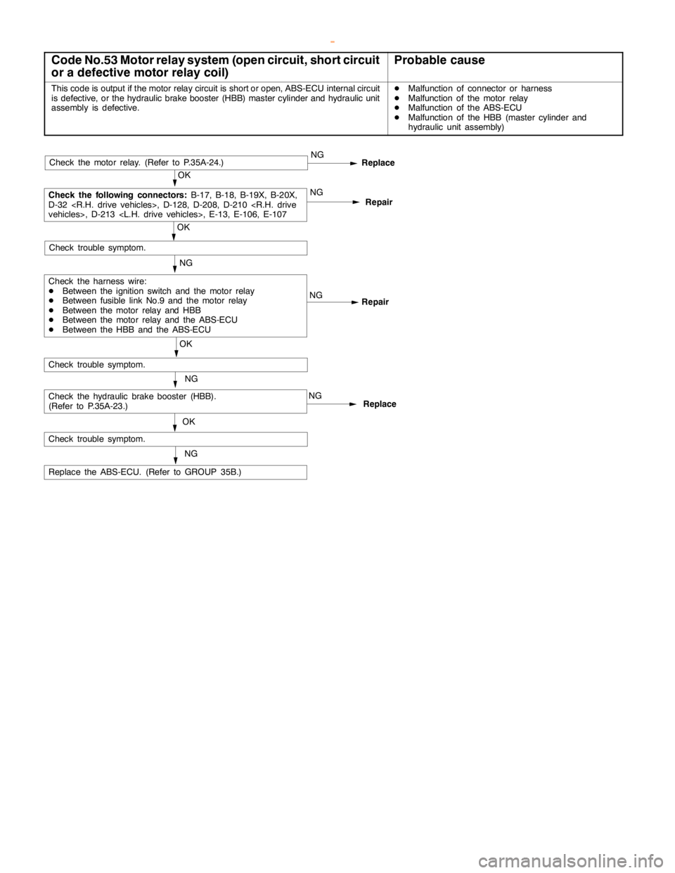
Code No.53 Motor relay system (open circuit, short circuit
or a defective motor relay coil)Probable cause
This code is output if the motor relay circuit is short or open, ABS-ECU internal circuit
is defective, or the hydraulic brake booster (HBB) master cylinder and hydraulic unit
assembly is defective.DMalfunction of connector or harness
DMalfunction of the motor relay
DMalfunction of the ABS-ECU
DMalfunction of the HBB (master cylinder and
hydraulic unit assembly)
NG
Replace the ABS-ECU. (Refer to GROUP 35B.)NG
Repair
NG
OK
Check trouble symptom.
Repair NGNG
OK
Check trouble symptom.
Replace
OK
Check the following connectors:
B-17, B-18, B-19X, B-20X,
D-32
Check the harness wire:
DBetween the ignition switch and the motor relay
DBetween fusible link No.9 and the motor relay
DBetween the motor relay and HBB
DBetween the motor relay and the ABS-ECU
DBetween the HBB and the ABS-ECU
Check trouble symptom.
NG
NG
Replace
OK
Check the motor relay. (Refer to P.35A-24.)
Check the hydraulic brake booster (HBB).
(Refer to P.35A-23.)
www.WorkshopManuals.co.uk
Purchased from www.WorkshopManuals.co.uk
Page 1219 of 1839

BASIC BRAKE SYSTEM -Troubleshooting35A-11
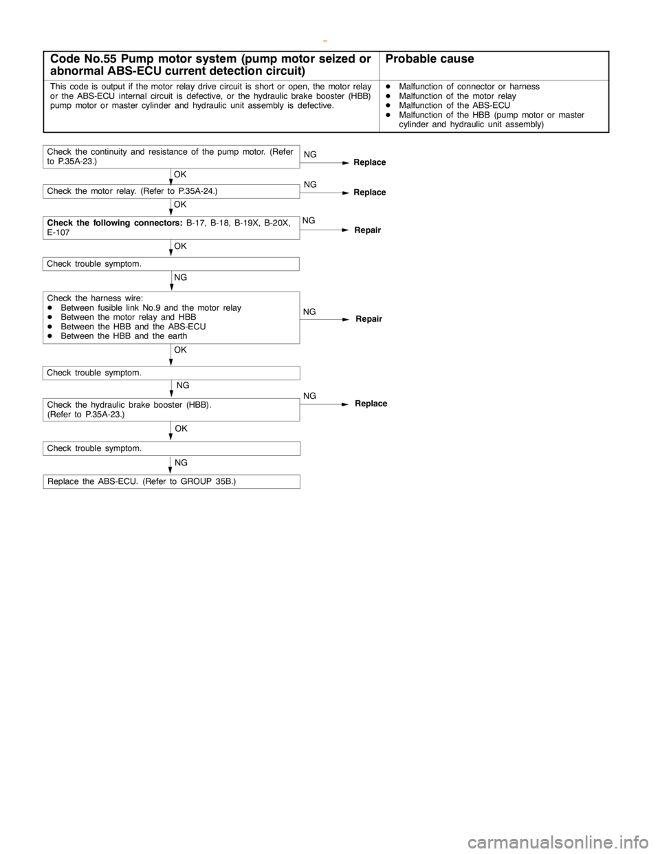
Code No.55 Pump motor system (pump motor seized or
abnormal ABS-ECU current detection circuit)Probable cause
This code is output if the motor relay drive circuit is short or open, the motor relay
or the ABS-ECU internal circuit is defective, or the hydraulic brake booster (HBB)
pump motor ormaster cylinder and hydraulic unit assembly is defective.DMalfunction of connector or harness
DMalfunction of the motor relay
DMalfunction of the ABS-ECU
DMalfunction of the HBB (pump motor or master
cylinder and hydraulic unit assembly)
NG
Repair
NG
OK
Check trouble symptom.
Repair NGNG
OK
Check trouble symptom.
Replace
OK
Check the following connectors:
B-17, B-18, B-19X, B-20X,
E-107
Check the harness wire:
DBetween fusible link No.9 and the motor relay
DBetween the motor relay and HBB
DBetween the HBB and the ABS-ECU
DBetween the HBB and the earthNG
Check the motor relay. (Refer to P.35A-24.)
NG
Replace the ABS-ECU. (Refer to GROUP 35B.)
Check trouble symptom.
NG
OKCheck the hydraulic brake booster (HBB).
(Refer to P.35A-23.)Replace NG
Replace
OKCheck the continuity and resistance of thepump motor.(Refer
to P.35A-23.)
www.WorkshopManuals.co.uk
Purchased from www.WorkshopManuals.co.uk
Page 1220 of 1839

BASIC BRAKE SYSTEM -Troubleshooting35A-12
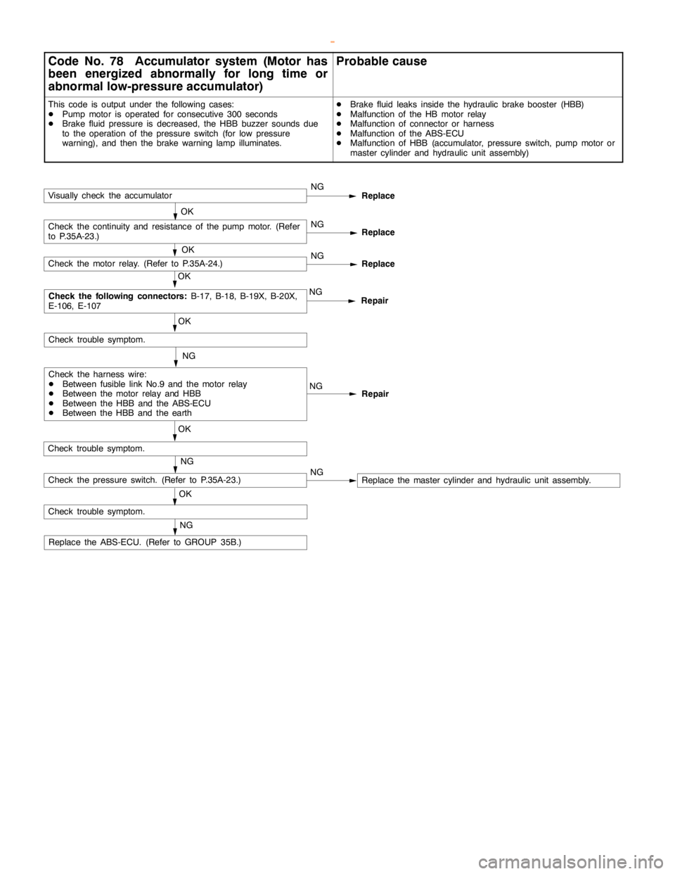
Code No. 78 Accumulator system (Motor has
been energized abnormally for long time or
abnormal low-pressure accumulator)Probable cause
This code is output under the following cases:
DPump motor is operated for consecutive 300 seconds
DBrake fluid pressure is decreased, the HBB buzzer sounds due
to the operation of the pressure switch (for low pressure
warning), and then the brake warninglamp illuminates.DBrake fluid leaks inside the hydraulic brake booster (HBB)
DMalfunction of the HB motor relay
DMalfunction of connector or harness
DMalfunction of the ABS-ECU
DMalfunction of HBB (accumulator, pressure switch,pump motor or
master cylinder and hydraulic unit assembly)
NG
Repair
NG
OK
Check trouble symptom.
Repair NGNG
OK
Check trouble symptom.
Replace
OK
Check the following connectors:
B-17, B-18, B-19X, B-20X,
E-106, E-107
Check the harness wire:
DBetween fusible link No.9 and the motor relay
DBetween the motor relay and HBB
DBetween the HBB and the ABS-ECU
DBetween the HBB and the earthNG
Check the motor relay. (Refer to P.35A-24.)
NG
Replace the ABS-ECU. (Refer to GROUP 35B.)
Check trouble symptom.
NG
OKCheck the pressure switch. (Refer to P.35A-23.)NG
Replace
OKCheck the continuity and resistance of thepump motor.(Refer
to P.35A-23.)NG
Replace
OKVisually check the accumulator
Replace the master cylinder and hydraulic unit assembly.
www.WorkshopManuals.co.uk
Purchased from www.WorkshopManuals.co.uk
Page 1264 of 1839

35B-1
ANTI-SKID
BRAKING SYSTEM
(ABS) <4WD>
CONTENTS
GENERAL INFORMATION 2..................
SERVICE SPECIFICATIONS 4.................
LUBRICANT Refer to GROUP 35A...........
SEALANTS Refer to GROUP 35A............
SPECIAL TOOLS 4..........................
TROUBLESHOOTING 4.......................
ON-VEHICLE SERVICE 27...................
Wheel Speed Sensor Output Voltage
Measurement 27...............................
ABS Valve Relay Continuity Check 28...........
Hydraulic Brake Booster (HBB) - Hydraulic Unit
Check 29......................................
Solenoid Valve Check 30.......................
When the Battery is Flat 31....................
Brake Pedal Check and Adjustment
Refer to GROUP 35A ..........................
Hydraulic Brake Booster (HBB) Operation Check
Refer to GROUP 35A ..........................
Hydraulic Brake Booster (HBB) Check
Refer to GROUP 35A ..........................Motor Relay Continuity Check
Refer to GROUP 35A ..........................
Bleeding Refer to GROUP 35A..................
Brake Fluid Level Sensor Check
Refer to GROUP 35A ..........................
Disc Brake Pad Check and Replacement
Refer to GROUP 35A ..........................
Brake Disc Thickness Check
Refer to GROUP 35A ..........................
Brake Disc Runout Check and Correction
Refer to GROUP 35A ..........................BRAKE PEDAL Refer to GROUP 35A........
HYDRAULIC BRAKE BOOSTER (HBB)
Refer to GROUP 35A ........................
HBB BUZZER Refer to GROUP 35A..........
FRONT DISC BRAKE Refer to GROUP 35A..
REAR DISC BRAKE Refer to GROUP 35A....
ABS-ECU 32................................
WHEEL SPEED SENSOR 33.................
G-SENSOR 36..............................
www.WorkshopManuals.co.uk
Purchased from www.WorkshopManuals.co.uk
Page 1270 of 1839

ABS <4WD> -Troubleshooting35B-7
INSPECTION CHART FOR DIAGNOSIS CODES
Diagnosis code
No.Diagnosis itemReference page
11Wheel speed sensor (FR) system (open circuit or short - circuit)35B-8
12Wheel speed sensor (FL) system (open circuit or short - circuit)35B-8
13Wheel speed sensor (RR) system (open circuit or short - circuit)35B-8
14Wheel speed sensor (RL) system (open circuit or short - circuit)35B-8
15Wheel speed sensor system (output signal abnormality)35B-9
16ABS-ECU or valve relay power supply system (abnormal voltage
drop or rise)35B-10
21Wheel speed sensor (FR) system35B-8
22Wheel speed sensor (FL) system35B-8
23Wheel speed sensor (RR) system35B-8
24Wheel speed sensor (RL) system35B-8
26Center differential lock switch system35B-11, 12
27Rear differential lock switch system35B-11, 12
32G sensor system35B-13
33Stop lamp switch system35B-14
41Control solenoid valve (FR)
systemIf there is no response to the
solenoid valve drive signal35B-15
42Control solenoid valve (FL)
systemcorresponding to each respec-
tive item
43Control solenoid valve (RR)
system
44Control solenoid valve (RL)
system
45Changeover solenoid valve
(FR) system
46Changeover solenoid valve
(FL) system
51Valve relay system (ON problem)35B-16
52Valve relay system(OFFproblem)35B-17
55HBB systemCarry out HBB troubleshoot-
ing. (Refer to GROUP 35A.)
63ABS-ECU system35B-32 (ABS-ECU replace-
ment)
NOTE
*: Code No.16 is erased from the memory if the condition returns to normal.
www.WorkshopManuals.co.uk
Purchased from www.WorkshopManuals.co.uk